Table of Contents
Advertisement
Quick Links
Advertisement
Table of Contents

Related Manuals for yellow jacket 68947


Summary of Contents for yellow jacket 68947
- Page 1 68945 and 68947 REFRIGERANT IDENTIFIER OPERATION MANUAL...
-
Page 2: Table Of Contents
Table of Contents Safety and Warnings…………………………………………………………………………………………………………………………………………………4 INTRODUCTION AND OVERVIEW.......... 6 ............. 6 ENERAL ............7 EATURES YELLOW JACKET R ......8 EFRIGERANT IDENTIFIER OMPONENTS 1.3.1 Base Unit ............8 1.3.2 R134a Sample Hose ..........8 1.3.3 R12 Sample Hose ..........9 1.3.4 R134a Tank Adapter Fitting ........ - Page 3 APPENDICES ............22 ............. 22 PARE ARTS B - S ..........22 PPENDIX PECIFICATIONS...
- Page 4 For Your Safety: PLEASE READ THIS MANUAL ENTIRETY BEFORE ATTEMPTING INSTALLATION OR OPERATION! Attempting to operate this refrigerant identifier without fully understanding its features and functions may result in unsafe conditions • Always use protective eye wear and observe proper safety procedures when working with pressurized gases.
- Page 5 General Cautions • Always inspect the sample hose before each use. Replace the hose if it appears cracked, frayed, obstructed or fouled with oil. • ALWAYS turn the compressor or automobile engine off before connecting the instrument to an air conditioning system. •...
-
Page 6: Introduction And Overview
The YELLOW JACKET Refrigerant Identifier will provide a fast, easy and accurate means to determine refrigerant purity in refrigerant storage cylinders or directly in vehicle air conditioning systems. -
Page 7: Features
The instrument interfaces with the user with an LCD graphic display, status indicator lamps, push button communication switches and an alarm horn. Alarm indications are provided to alert of instrument fault conditions contaminated refrigerant presence. Direct percent weight concentrations sample refrigerant provided on the display as well as user directions and prompts. -
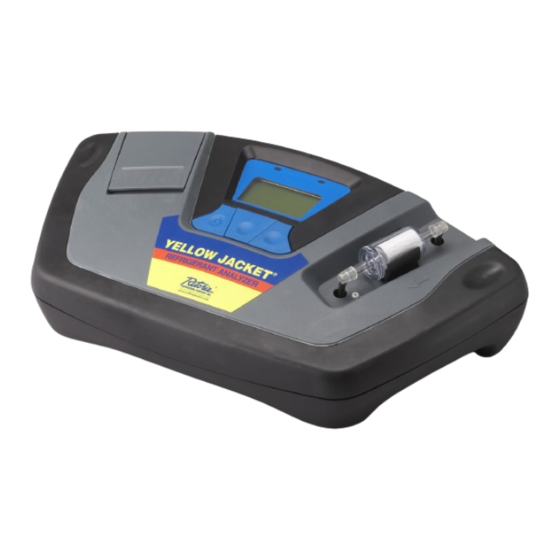
Page 8: Base Unit
Components 1.3.1 Base Unit The base unit houses the Graphic Display, Infrared Bench, Electrical Connections, and Optional Printer Module. These components require maintenance, therefore there serviceable components internal to the instrument, and disassembly will void the warranty. Sample Filter Control Panel Printer Door Air Intake Port 1.3.2... -
Page 9: R12 Sample Hose
1.3.3 R12 Sample Hose Identifier End Service End (1/4 SAE Flare Nut) The 6-foot (1.8 meter) R12 Sample Hose is constructed of a nylon inner tube and a polyurethane outer tube. The inner tube will handle all of the refrigerant transfer and will provide containment up to 300psig. -
Page 10: Control Panel
1.3.6 Control Panel The Control Panel serves as the main user interface. The Control Panel features three soft key buttons that change their function as the instrument changes modes. The current function for each button is displayed by the soft key label at the bottom of the graphic display. -
Page 11: Hard Shell Storage/Carrying Case
12VDC Power Input Sample Inlet (Battery Clips) Sample Outlet Battery Charge Port 1.3.8 Hard Shell Storage/Carrying Case hard shell storage/carrying case custom refrigerant identifier. provides rugged protection instrument as well as convenient storage for all components. enclosure is general purpose and is not watertight. -
Page 12: First Use
PERATION 2.1 First Use 2.1.1 Battery Installation (Optional) refrigerant identifier has, option, internal rechargeable battery. If your uit is equipped with the optional rechargeable battery, you must first install and charge the battery prior to use. NOTE: The refrigerant identifier can be operated with or without the battery using the supplied battery clips. -
Page 13: Turning O N The 2.3 Calibration
Note: Charge the battery for a minimum of 4 hours with the supplied charger prior to first use. To remove the battery, simply tug gently on the nylon strap, being sure to pull straight up, until the battery is dislodged. 2.2 Turning On the Unit Connect the supplied vehicle power cable to the 12VDC power input jack on the back of the unit. -
Page 14: Viewing The Test Result
CALIBRATING - CALIBRATING - CALIBRATION TIME NOTE HAS EXPIRED THIS WILL ONLY REPLACE FILTER DISCONNECT HOSE TAKE 30 SECONDS WHEN WHITE FROM VEHICLE AND ELEMENT BEGINS PRESS CAL TO TO SHOW RED RECALIBRATE SPOTS ON OUTSIDE DIAMETER Figure 4 Figure 5 Figure 6 After calibrating, the unit will display the screen shown in Figure Connect the hose to the vehicle, (for R134a open the valve) and... -
Page 15: Efrigerants
If the refrigerant tested is 98% pure or better, and the air content is less than 10%, the “PASS” screen will display and the Green LED will illuminate. Should the refrigerant be less than 98% pure or the air content greater than 10%, the “FAIL” screen will display and the Red LED will illuminate. -
Page 16: Printing The Test Results
2.6 Printing the Test Results For units equipped with the optional built-in printer module, the test results can be printed by selecting the “PRINT” button. After the print is complete, carefully tear off the printout and the unit will return to the previous screen. Additional printouts may be made following the same procedure. -
Page 17: Maintenance & Troubleshooting
& T AINTENANCE ROUBLESHOOTING 3.1 Setting the Elevation During initial power-up, YELLOW JACKET Refrigerant Identifier will indicate that the elevation has not been set. set the elevation, press the “Help” button on the “Ready to Air Cal” screen as shown in Section 2.2, Figure 3. The screen will display several options as shown in Figure 20. -
Page 18: Lcd Contrast
3.2 Setting the LCD Contrast The YELLOW JACKET Refrigerant Identifier features an adjustable LCD contrast varying light conditions. adjust contrast, press the “HELP” button on the “Ready to Air Cal” screen as shown in Section 2.2, Figure 3. The screen will display several options as shown in Figure 17. -
Page 19: Changing The Sample Filter
3.5 Changing the Printer Paper The YELLOW JACKET Refrigerant Identifiers that are equipped with on- board printers use an inexpensive thermal paper for printing. paper roll should be changed when a red stripe appears on the left... -
Page 20: Low Battery Warning
To change the paper roll, press the “HELP” button on the “Ready to Air Cal” screen as shown in Section 2.2, Figure 3. The screen will display several options as shown in Figure 28. Press the “SET” button to advance to the screen shown in Figure 29 and then press the “FEED”... -
Page 21: E Rror M Essages
3.7 Error Messages In the unlikely event that an “Error” message is displayed on the screen, power off the unit, take it to a location outside of the shop environment where fresh air is available and turn the unit back “Error”... - Page 22 PPENDICES 4.1 Spare Parts List PART NUMBER DESCRIPTION Optional internal rechargeable battery kit with 68948 battery and 110V charger Optional 110/220V power adapter 68949 Thermal printer paper – 1 roll 68950 In line identifier replacement filter 68977 R-12 replacement hose 68978 R-134a replacement hose 68979...
Need help?
Do you have a question about the 68947 and is the answer not in the manual?
Questions and answers