Table of Contents
Advertisement
Quick Links
YELLOW JACKET®
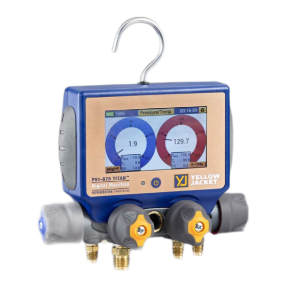
P51-870 TITAN® User Manual
P/N 40870, 40875, 40877
NOTE: These Instructions do not cover the manifold attached to the instrument.
For instructions on use of the TITAN® 4-Valve Manifold, please visit:
https://yellowjacket.com/product/titan-4-valve-test-and-charging-manifold/.
The Manifold Instructions are under the Documents tab.
REV D
Advertisement
Table of Contents

Related Manuals for yellow jacket 40870


Summary of Contents for yellow jacket 40870
- Page 1 YELLOW JACKET® P51-870 TITAN® User Manual P/N 40870, 40875, 40877 NOTE: These Instructions do not cover the manifold attached to the instrument. For instructions on use of the TITAN® 4-Valve Manifold, please visit: https://yellowjacket.com/product/titan-4-valve-test-and-charging-manifold/. The Manifold Instructions are under the Documents tab.
-
Page 2: Table Of Contents
Table of Contents Ch. 1: Before You Start…………………….…………………………………………………………..……1 Contacting Ritchie Engineering..…………………….……………………………………………………………….1 Safety Information……………………………………………………….…………………………………………………1 Ch. 2: Getting Started…………………………………………………………..……………………………3 Getting to Know Your P51-870 TITAN®…………………………………………………….……………………..3 Turning the instrument On and Off………………………………………………………………………………….3 Interacting with the Device……………………………………………………………………………………………..4 Connecting and Using the Temperature Clamps………………………………………………………………4 Connecting and Using the Vacuum Sensor……………………………………………………………………….5 Interpreting the Battery Life Indicator………………………………………………………………………….….5 Charging the Battery………………………………………………………………………………………..…………….6 Operating the Backlight…………………………………………………………………………………………..……..6... - Page 3 Ch. 4: Settings…………………………………………….……………………………………………………20 Settings Menus Overview…………………………………………………….…………………………………..20 General Settings Menu..……………………………………………………………………………………….20 Zeroing the Pressure Transducers………………………………………………………………………20 Calibrating the Touchscreen………………………………………………………………………………21 Refrigerant Settings Menu…………………………………………………………………………………….….21 Unit Settings Menu…………………………………………………………………………………………………..21 Pressure Units……………………………………………………………………………………………….….22 Temperature Units…………………………………………………….………………………………………22 Vacuum Units……………………………………………………………………………………………….…..22 Device Settings Menu……………………………………………………………………………………………….22 Brightness……………………………………………………………………………………………………..….22 Backlight Timer………………………………………………………………………..………………..……..22 Auto Off……………………………………………………………………………………….……………………23 Logging Rate…………………………………………………………………………………………..…..……23 Ch. 5: YJACK View App Integration……………………………………………………………..…24 Overview………………………………………………………………………………………………………………………24 Operation of the YJACK VIEW®...
-
Page 4: 1: Before You Start
Chapter 1: Before You Start Contacting Ritchie Engineering: To order accessories, receive assistance, or locate the nearest YELLOW JACKET distributor. ® Corporate Office and Mailing Address: Ritchie Engineering Co, Inc. YELLOW JACKET Products Division ® 10950 Hampshire Avenue South, Bloomington, MN 55438-2623 U.S.A. - Page 5 Do not operate the instrument around To avoid damage to equipment, follow these • guidelines: explosive gas, vapor, or dust. • Do not allow pressures beyond the • Various refrigerants have been intentionally specifications listed in this manual. excluded for very significant safety reasons. Never use refrigerants in this instrument that are not listed in the Set-up menu.
-
Page 6: 2: Getting Started
Chapter 2: Getting Started Getting to Know Your P51-870 TITAN®: Figure 1: P51-870 Front View Figure 2: P51-870 Rear View 1. Touchscreen Display 2. Power Button 3. RGB LED 4. Temperature Clamp Mounting Pegs 5. Silicone Plugs 6. T1 Connector 7. -
Page 7: Interacting With The Device
Interacting with the device: The P51-870 TITAN® features a 4.3” full color resistive touchscreen for improved usability and durability. To interact with the device, use a finger or stylus to touch anywhere on the screen. All interactive buttons are conveniently displayed with the same golden yellow color as seen in Figures 4 &... -
Page 8: Connecting And Using The Vacuum Sensor
Connecting and Using the Vacuum Sensor: The P51-870 TITAN® includes a (67044) YJ vacuum sensor, pictured in Figure 8, which can be used with this unit to measure the current depth of vacuum within a system. To connect the vacuum probe to the device, remove either of the two clear silicone plugs on the back of the device covering the A1 and A2 connectors. -
Page 9: Charging The Battery
features accessible in the device settings menu (see Pages 22-23). The most influencing factor on battery life is the backlight intensity, be sure to adjust the backlight level accordingly depending on your current viewing conditions. Charging the Battery: To ensure maximum battery life, make sure the P51-870 TITAN® is charged before and after each job session. - Page 10 After completing a job, the datalog files can be accessed by connecting the instrument to a PC. To connect the P51-870 TITAN® to a PC, connect the provided data transfer cable to the micro- USB port on the back of device shown in Figures 13 and 14. Plug the opposite end into the USB port on a PC.
-
Page 11: Interpreting The Rgb Led
datalog files. If the device reaches max storage and has not Table 2-1: Sampling Rates and Time to Maximum Memory Capacity been cleared, it will cease to log data until all files have been cleared from the device. Be sure to select the proper logging rate based on the intended length of the datalog session. -
Page 12: 3: Modes Of Operation
Chapter 3: Modes of Operation Modes Menu The P51-870 TITAN® will always start up on the Modes Menu shown in Figure 16 below. Tap any of the three buttons labeled “Pressure/Temperature, Evacuation, Pressure Hold” to start a Pressure/Temperature, Evacuation, or Pressure Hold session respectively. The general settings menu can be accessed by tapping the gear icon in the upper right-hand corner. -
Page 13: Interpreting The Pressure Analog Gauges
Figure 17: Pressure/Temperature Mode Diagram 1. Battery Level Indicator 2. Session Timer 3. Currently Selected Pressure & Temperature Units – Unit Settings Menu Shortcut 4. Currently Selected System Refrigerant – Refrigerant Settings Shortcut 5. Low Side Pressure & Temperature Measurement 6. -
Page 14: Operating Pressure/Temperature Mode
as it is recorded. Any old data will be replaced by newer data as the leader line advances to the right, each graph completely overwrites every 100 seconds (approx. 1.5 minutes). Scaling Value Central Value Figure 18: Pressure/Temperature Line Graphs Each line graph centers on the first pressure or temperature measurement recorded when beginning a new plot, this value is displayed adjacent to the plot line to the left of each graph. -
Page 15: Evacuation Mode
Evacuation Mode Overview: Once the refrigerant has been recovered from the system, the P51-870 TITAN® can be used to accurately monitor the system evacuation. Evacuation mode displays the current vacuum pressure in digital, analog, and graphical form, percent change per minute, estimated time remaining, target vacuum level, and the vacuum hold timer. -
Page 16: Interpreting The Evacuation Graph
in vacuum pressure during a system evacuation. Because the evacuation operates on a logarithmic scale, the resolution of the needle movement increases in a deeper vacuum meaning small fluctuations in vacuum pressure become more apparent in a deeper vacuum. Interpreting the Evacuation Graph: In addition to the evacuation gauge, evacuation mode also features a fully functional evacuation line graph like those in Pressure/Temperature mode. -
Page 17: Pressure Hold Mode - Pressure Decay Test
the evacuation or select a new mode of operation. If the vacuum hold timer is not desired, simply tap the Hold button until NONE is displayed. Figure 20: Evacuation - Pressure Hold Test Prompt NOTE: Using the vacuum hold timer can help to ensure that all refrigerant has been evacuated from the system and the system is free of non-condensables. -
Page 18: Interpreting The Pressure Decay Gauge
Figure 21: Pressure Hold – Pressure Decay Test Diagram 1. Battery Indicator 2. Currently Selected Units – Unit Settings Menu Shortcut 3. Hold Timer 4. Currently Selected Refrigerant – Refrigerant Settings Menu Shortcut 5. Initial Pressure (Pi) 6. Change in Pressure (Pi-Pc) 7. -
Page 19: Operating The Pressure Decay Mode
Any old data will be replaced by newer data as the leader line advances to the right, the line graph will completely overwrite every 200 seconds (approx. 3.5 minutes). The line graph centers on the first pressure measurement recorded when beginning a new plot, this value is displayed adjacent to the plot line to the left of the graph. -
Page 20: Pressure Hold Mode - Pressure Rise Test
During the pressure decay test, Pc will adjust as the current system pressure changes. Pi-Pc will adjust to reflect the change between the initial system pressure and current system pressure. Limit will display the limit pressure as determined by the percent allowable change. System pressure dropping below this value within the time limit as set by the test duration will trigger a failure. -
Page 21: Interpreting The Pressure Rise Gauge
Figure 26: Pressure Hold Mode – Pressure Rise Test Diagram 1. Battery Life Indicator 2. Session Timer 3. Currently Selected Vacuum Units – Unit Settings Menu Shortcut 4. Currently Selected Refrigerant – Refrigerant Settings Menu Shortcut 5. General Settings Button 6. -
Page 22: Operating The Pressure Rise Test
measurement is plotted. The line graph fully overwrites the old data every 200 seconds (approx. 3.5 minutes) and will begin again from the left side of the graph. Operating the Pressure Rise Test: The pressure rise test can be accessed through completion of an evacuation (See page 13). -
Page 23: 4: Settings
Figure 28: Pressure Rise Test - FAIL Figure 29: Pressure Rise Test - PASS Chapter 4: Settings Settings Menus Overview The P51-870 TITAN® settings menus are separated into four menus: unit settings, refrigerant settings, device settings, and general settings. While on any modes screen or the modes menu, the general settings menu can be quickly accessed by tapping the gear icon in the top right corner. -
Page 24: Calibrating The Touchscreen
Calibrating the Touchscreen: If the touchscreen seems unresponsive or poorly aligned, it may benefit to re-calibrate the display. The touchscreen display can be re-calibrated one of two ways: through the general settings menu or interaction with the power button. To calibrate the display through the general settings menu, navigate to the general settings menu and tap the “Calibrate Display”... -
Page 25: Pressure Units
the desired units have been selected, tap the back button in the upper right corner to save new selections. Pressure Units: Pressure units are used to display pressure measurements while in pressure/temperature and pressure decay mode. This unit can be adjusted to one of six pressure units: psig, psia, bar, kg/cm^2, MPa, and kPa. -
Page 26: Auto Off
Auto Off: The auto off timer will automatically power the unit down if there has been no user input for the selected duration of time. This feature can be used to significantly increase the battery life of the manifold. The Auto Off Timer can be set to four increments: 15m, 30m, 1hr and None. Selecting None will prevent the unit from auto powering off. -
Page 27: 5: Yjack View App Integration
Chapter 5: YJACK VIEW® App Integration Overview: The P51-870 TITAN® features a Bluetooth® low energy radio and is fully compatible with both the iOS and Android YJACK VIEW® Apps V3.0 or later. The YJACK VIEW® app in conjunction with the P51-870 TITAN®... -
Page 28: 6: Maintenance
Chapter 6: Maintenance Overview: Basic operator maintenance is covered in this chapter. For more extensive maintenance and for repair, contact Ritchie Customer Service. See Chapter 1 for contact information. General Maintenance: Since this instrument may be used in the presence of a wide range of chemical liquids and vapors, it is recommended that the case be cleaned often with a damp cloth and mild detergent such as dish soap. -
Page 29: Software Updates
Software Updates: Details related to software updates are available online at www.yellowjacket.com or by contacting Ritchie Engineering. See Chapter 1 for contact information. Chapter 7: Device Specifications Table 7-1: Physical Specifications Maximum Pressure 700 psia (48.3 bar) Operating Temperature 140 to -4°F (60 to -20°C) Storage Temperature 140 to -4°F (60 to -20°C) 4 hrs continuous Backlight... -
Page 30: 8: Troubleshooting Guide
Chapter 8: Troubleshooting Guide Table 8-1: P51 Troubleshooting Model(s) Problem Possible Cause(s) Possible Solution(s) Check backlight auto-dimming timer (P51-870 only) Screen is auto-dimming, backlight is off P51-860 Tap power button or anywhere on display to power on backlight (P51-870 only) Screen does not display anything P51-870 Device is not powering on...
Need help?
Do you have a question about the 40870 and is the answer not in the manual?
Questions and answers