Table of Contents
Advertisement
Available languages
Available languages
Quick Links
Betriebsanleitung
Operating instructions
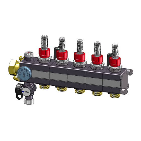
Heizkreisverteiler
Heating circuit manifold
Version: 04.2024.0
ID: 900.000.0487
Copyright 2024 AFRISO-EURO-INDEX GmbH. Alle Rechte vorbehalten.
ProCalida®
Typ: MC 1
Lindenstraße 20
74363 Güglingen
Telefon +49 7135 102-0
Service +49 7135 102-211
Telefax +49 7135 102-147
info@afriso.com
www.afriso.com
DE
Advertisement
Table of Contents

Related Manuals for AFRISO ProCalida MC 1


Summary of Contents for AFRISO ProCalida MC 1
- Page 1 Betriebsanleitung Operating instructions Heizkreisverteiler Heating circuit manifold ProCalida® Typ: MC 1 Copyright 2024 AFRISO-EURO-INDEX GmbH. Alle Rechte vorbehalten. Lindenstraße 20 74363 Güglingen Telefon +49 7135 102-0 Service +49 7135 102-211 Telefax +49 7135 102-147 info@afriso.com Version: 04.2024.0 www.afriso.com ID: 900.000.0487...
- Page 2 Betriebsanleitung Heizkreisverteiler ProCalida® Typ: MC 1 Copyright 2024 AFRISO-EURO-INDEX GmbH. Alle Rechte vorbehalten. Lindenstraße 20 74363 Güglingen Telefon +49 7135 102-0 Service +49 7135 102-211 Telefax +49 7135 102-147 info@afriso.com Version: 04.2024.0 www.afriso.com ID: 900.000.0487...
-
Page 3: Über Diese Betriebsanleitung
Über diese Betriebsanleitung Über diese Betriebsanleitung Diese Betriebsanleitung beschreibt den Heizkreisverteiler ProCalida® „MC 1“ (im folgenden auch „Produkt“). Diese Betriebsanleitung ist Teil des Produkts. • Sie dürfen das Produkt erst benutzen, wenn Sie die Betriebsanleitung vollständig gelesen und verstanden haben. •... - Page 4 Informationen zur Sicherheit Informationen zur Sicherheit Warnhinweise und Gefahrenklassen In dieser Betriebsanleitung finden Sie Warnhinweise, die auf potenzielle Gefahren und Risiken aufmerksam machen. Zusätzlich zu den Anweisungen in dieser Betriebsanleitung müssen Sie alle am Einsatzort des Produktes gel- tenden Bestimmungen, Normen und Sicherheitsvorschriften beachten. Stel- len Sie vor Verwendung des Produktes sicher, dass Ihnen alle Bestimmun- gen, Normen und Sicherheitsvorschriften bekannt sind und dass sie befolgt werden.
-
Page 5: Informationen Zur Sicherheit
Informationen zur Sicherheit Bestimmungsgemäße Verwendung Dieses Produkt eignet sich ausschließlich für den Einsatz in Flächenhei- zungssystemen und Flächenkühlsystemen. Eine andere Verwendung ist nicht bestimmungsgemäß und verursacht Gefahren. Stellen Sie vor Verwendung des Produkts sicher, dass das Produkt für die von Ihnen vorgesehene Verwendung geeignet ist. Berücksichtigen Sie dabei mindestens folgendes: •... -
Page 6: Transport Und Lagerung
Transport und Lagerung Qualifikation des Personals Arbeiten an und mit diesem Produkt dürfen nur von Fachkräften vorgenom- men werden, die den Inhalt dieser Betriebsanleitung und alle zum Produkt gehörenden Unterlagen kennen und verstehen. Die Fachkräfte müssen aufgrund ihrer fachlichen Ausbildung, Kenntnisse und Erfahrungen in der Lage sein, mögliche Gefährdungen vorherzusehen und zu erkennen, die durch den Einsatz des Produkts entstehen können. - Page 7 Produktbeschreibung Produktbeschreibung Übersicht Standardausführung Zubehör (optional) A. Entlüftungsschraube 1. Kugelhahn B. Hubventil 2. Anschlusswinkel C. Fläche für Kennzeichnungsschilder 3. Schnellentlüfter D. Absperrventil 4. Stellantrieb E. Durchflussmesser F. KFE-Hahn G. Thermometer ProCalida® MC 1...
- Page 8 Produktbeschreibung Abmessungen 4.2.1 Abmessungen mit Durchflussmesser Heizkreis A (mm) 100 150 200 200 250 300 300 350 350 B (mm) 118 118 118 118 118 168 L (mm) 185 235 285 335 385 435 485 535 585 635 685 ProCalida® MC 1...
- Page 9 Produktbeschreibung 4.2.2 Abmessungen mit Absperrventil oder dynamischem Regulier- ventil Heizkreis A (mm) 100 150 200 200 250 300 300 350 350 B (mm) 118 118 118 118 118 168 L (mm) 185 235 285 335 385 435 485 535 585 635 685 ProCalida®...
-
Page 10: Montage
Montage Technische Daten Parameter Wert Allgemeine Daten Hauptanschluss G1 mit Überwurfmutter Heizkreisanschluss Eurokonus Betriebstemperatur und -druck Maximal 60 °C bei 6 bar Maximal 90 °C bei 3 bar Wassermenge pro Verteiler 3,5 m -Wert Vor-/Rücklaufventil 1,0 m Lieferbare Größen 2-12 Heizkreise Montage WARNUNG VERBRENNUNGEN DURCH HEISSE FLÜSSIGKEIT... - Page 11 Montage Produkt montieren 1. Montieren Sie die schrä- gen Halter (grau) am obe- 4,8 x 19 ren Verteiler (A – Rück- lauf). 2. Montieren Sie die gera- den Halter (schwarz) am unteren Verteiler (B – Vor- lauf). 4 x 12 mindestens 180 mm 4,8 x 19...
- Page 12 Montage 3. Schieben Sie den Halter seitlich ein (C) oder ste- cken Sie den Halter auf und drehen diesen (D). 4. Verteilen Sie die Halter gleichmäßig. 5. Befestigen Sie die Halter mit Schrauben an den Schienen im Verteiler- schrank oder an der Wand (siehe Schritt 1).
- Page 13 Montage Schnellentlüfter montieren (optional) WARNUNG HEISSE MEDIEN Medien in Heizungsanlagen stehen unter einem hohen Druck und können Tem- peraturen über 100 °C erreichen. • Stellen Sie sicher, dass das Medium abgekühlt ist, bevor Sie die Anlage öff- nen und das Produkt montieren. •...
- Page 14 Inbetriebnahme Inbetriebnahme Produkt in Betrieb nehmen (mit Durchflussmesser oder Absperr- ventil) 1. Beaufschlagen Sie die Heizungsanlage mit Druck. 2. Füllen und spülen Sie die Heizungsanlage über die Rohrleitungen oder die KFE-Hähne (E). 3. Öffnen Sie, zum Befüllen und Spülen über die KFE- Hähne (E), die weißen Handräder (D).
- Page 15 Inbetriebnahme Maximal 1 x 11.Entlüften Sie die Hei- zungsanlage an der Ent- lüftungsschraube (F). ProCalida® MC 1...
- Page 16 Inbetriebnahme Produkt in Betrieb nehmen (mit Vario-DP) Stellen Sie sicher, dass das Produkt nur über den Rücklauf befüllt wird. Stellen Sie sicher, dass die Anlage während und nach der Befüllung ent- lüftet wird. 1. Schließen Sie einen Schlauch an den Schlauchanschluss des Füllhahns (G) an.
- Page 17 Inbetriebnahme 6. Schließen Sie alle Vorlaufventile (B). 7. Öffnen Sie das Vorlaufventil des zu spülenden Heizkreises minimal. 8. Spülen und befüllen Sie den Heizkreis mit maximal 2 bar. 9. Öffnen Sie dann das Vorlaufventil vollständig. 10.Schließen Sie das Vorlaufventil des befüllten Heizkreises. - Das Rücklaufventil bleibt offen.
- Page 18 Inbetriebnahme Vorlaufventile einstellen 6.4.1 Mit Durchflussmesser 1. Öffnen Sie das Vorlaufventil so weit bis die errechnete Wasser- menge (A) am Durchflussmesser angezeigt wird. 2. Drehen Sie den Ring bis zum Anschlag des Vorlaufventils. 6.4.2 Mit Absperrventil Abbildung 1: Diagramm zur Ermittlung der Durchflussmenge ProCalida®...
-
Page 19: Wartung
Wartung 1. Entnehmen Sie den Einstellwert aus Abbildung 1. 2. Schließen Sie das Vorlaufventil. 3. Stellen Sie den Einstellwert (A) am Ring ein. 4. Öffnen Sie das Vorlaufventil. Wartung Führen Sie mindestens einmal jährlich eine Sichtprüfung auf Dichtheit durch. Bei Bedarf können die Schaugläser der Durchflussmesser (unter Druck) gereinigt werden. -
Page 20: Außerbetriebnahme Und Entsorgung
2. Entsorgen Sie das Produkt. Rücksendung Vor einer Rücksendung Ihres Produkts müssen Sie sich mit uns in Verbin- dung setzen (service@afriso.de). Gewährleistung Informationen zur Gewährleistung finden Sie in unseren Allgemeinen Geschäftsbedingungen im Internet unter www.afriso.com oder in Ihrem Kauf- vertrag. ProCalida® MC 1... -
Page 21: Ersatzteile Und Zubehör
Ersatzteile und Zubehör Ersatzteile und Zubehör Produkt Artikelbezeichnung Art.-Nr. Abbildung Heizkreisverteiler Auf Anfrage ProCalida® „MC1“ Ersatzteile und Zubehör Artikelbezeichnung Art.-Nr. Durchflussmesser-Set, 80821 5 x Durchflussmesser 0,75-3,75 l/min mit Montagewerkzeug Rücklaufventil-Set, 80836 5 x Rücklaufventil M30 x 1,5 AG mit Montagewerkzeug Füll- und Entleerhahn-Set, 76867 2 x KFE-Hahn... - Page 22 Anhang Anhang 13.1 Diagramm ProCalida® MC 1...
- Page 23 Operating instructions Heating circuit manifold ProCalida® Type: MC 1 Copyright 2024 AFRISO-EURO-INDEX GmbH. All rights reserved. Lindenstraße 20 74363 Güglingen Telephone +49 7135 102-0 Service +49 7135 102-211 Telefax +49 7135 102-147 info@afriso.com Version: 04.2024.0 www.afriso.com ID: 900.000.0487...
- Page 24 About these operating instructions About these operating instructions These operating instructions describe the heating circuit manifold ProCal- ida® "MC 1" (also referred to as "product" in these operating instructions). These operating instructions are part of the product. • You may only use the product if you have fully read and understood these operating instructions.
- Page 25 Information on safety Information on safety Safety messages and hazard categories These operating instructions contain safety messages to alert you to poten- tial hazards and risks. In addition to the instructions provided in these oper- ating instructions, you must comply with all directives, standards and safety regulations applicable at the installation site of the product.
-
Page 26: Information On Safety
Information on safety Intended use This product may only be used for surface heating systems and surface cool- ing systems. Any use other than the application explicitly permitted in these operating instructions is not permitted and causes hazards. Verify that the product is suitable for the application planned by you prior to using the product. -
Page 27: Transport And Storage
Transport and storage Qualification of personnel Only appropriately trained persons who are familiar with and understand the contents of these operating instructions and all other pertinent product docu- mentation are authorized to work on and with this product. These persons must have sufficient technical training, knowledge and expe- rience and be able to foresee and detect potential hazards that may be caused by using the product. - Page 28 Product description Product description Overview Standard version Accessories (optional) A. Vent screw 1. Ball valve B. Stroke valve 2. Angular connection piece C. Surface for designation plates 3. Quick air vent D. Shut-off valve 4. Actuator E. Flow meter F. Boiler filling and drain valve KFE G.
-
Page 29: Product Description
Product description Dimensions 4.2.1 Dimensions with flow meter Heating circuit A (mm) 100 150 200 200 250 300 300 350 350 B (mm) 118 118 118 118 118 168 L (mm) 185 235 285 335 385 435 485 535 585 635 685 ProCalida®... - Page 30 Product description 4.2.2 Dimensions with shut-off valve or dynamic control valve Heating circuit A (mm) 100 150 200 200 250 300 300 350 350 B (mm) 118 118 118 118 118 168 L (mm) 185 235 285 335 385 435 485 535 585 635 685 ProCalida®...
-
Page 31: Technical Specifications
Mounting Technical specifications Parameter Value General specifications Main connection G1 with union nut Heating circuit connection eurocone Operating temperature and pressure Maximum 60 °C at 6 bar Maximum 90 °C at 3 bar Water volume per manifold 3.5 m Flow coefficient K flow/return valve 1.0 m Available sizes... -
Page 32: Mounting The Product
Mounting Mounting the product 1. Mount the slanted brack- ets (grey) to the top mani- 4.8 x 19 fold (A – return). 2. Mount the straight brack- ets (black) to the bottom manifold (B – flow). 4 x 12 at least 180 mm 4.8 x 19 4 x 12... - Page 33 Mounting 3. Slide the bracket into the manifold from the side (C) or plug in the bracket and turn it (D). 4. Evenly distribute the brackets. 5. Fasten the brackets to the rails in the cabinet or to the wall (see step 1). ProCalida®...
- Page 34 Mounting Mounting a quick air vent (optional) WARNING HOT MEDIA Media in heating systems are under high pressure and can have temperatures of more than 100 °C. • Verify that the medium has cooled down before opening the system and mounting the product.
- Page 35 Commissioning Commissioning Commissioning the product (with flow meter or shut-off valve) 1. Apply pressure to the heating system. 2. Fill and flush the heating system via the pipes or the boiler filling and drain valves KFE (E). 3. Open the white hand wheels (D) for filling and flushing via the boiler fill- ing and drain valves KFE...
- Page 36 Commissioning Maximum 1 11.Vent the heating system via the vent screw (F). ProCalida® MC 1...
- Page 37 Commissioning Commissioning the product (with Vario-DP) Ensure that the product is only filled via the return. Verify that the system is de-aerated during and after filling. 1. Connect a hose to the hose connection of the filling valve KFE (G). 2.
- Page 38 Commissioning 8. Flush and fill the heating circuit with a maximum of 2 bar. 9. Then open the flow valve fully. 10.Close the flow valve of the filled heating circuit. - The return valve remains open. 11.Repeat steps 7 to 10 for each additional heating circuit. 12.Close the hand wheel (C and F) at the filling and vent valve.
- Page 39 Commissioning 6.4.1 With flow meter 1. Open the flow valve until the cal- culated water volume is indicated at the flow meter (A). 2. Turn the ring all the way to the mechanical stop of the flow valve. 6.4.2 With shut-off valve Fig.
-
Page 40: Maintenance
Maintenance 1. Take the adjustment value shown in figure 1. 2. Close the flow valve. 3. Set the adjustment value (A) via the ring. 4. Open the flow valve. Maintenance Perform a visual inspection for tightness at least once per year. If necessary, the sight glasses of the flow meters can be cleaned (under pres- sure). -
Page 41: Decommissioning / Disposal
1. Dismount the product (see chapter "Mounting", reverse sequence of steps). 2. Dispose of the product. Returning the device Get in touch with us before returning your product (service@afriso.de). Warranty See our terms and conditions at www.afriso.com or your purchase contract for information on warranty. ProCalida® MC 1... -
Page 42: Spare Parts And Accessories
Spare parts and accessories Spare parts and accessories Product Product designation Part no. Figure Heating circuit manifold On request ProCalida® "MC1" Spare parts and accessories Product designation Part no. Flow meter set, 80821 5 x flow meter 0.75-3.75 l/min with mounting tool Return valve set, 80836 5 x return valve M30x1.5 male thread with mounting tool... - Page 43 Appendix Appendix 13.1 Chart ProCalida® MC 1...
Need help?
Do you have a question about the ProCalida MC 1 and is the answer not in the manual?
Questions and answers