Table of Contents
Advertisement
Available languages
Available languages
Quick Links
Betriebsanleitung
Reglermodul (Funk)
Version: 02.2016.0
ID: 900.000.0710
Copyright 2015 AFRISO-EURO-INDEX GmbH. Alle Rechte vorbehalten.
Produktfamilie CosiTherm®
Telefon +49 7135-102-0
Service +49 7135-102-211
Telefax +49 7135-102-147
Typ: F2
Typ: F6
Typ: F2A
Typ: F6A
Lindenstraße 20
74363 Güglingen
info@afriso.com
www.afriso.com
Advertisement
Table of Contents

Related Manuals for AFRISO CosiTherm F2


Summary of Contents for AFRISO CosiTherm F2
- Page 1 Betriebsanleitung Reglermodul (Funk) Produktfamilie CosiTherm® Typ: F2 Typ: F6 Typ: F2A Typ: F6A Copyright 2015 AFRISO-EURO-INDEX GmbH. Alle Rechte vorbehalten. Lindenstraße 20 74363 Güglingen Telefon +49 7135-102-0 Service +49 7135-102-211 Telefax +49 7135-102-147 info@afriso.com Version: 02.2016.0 www.afriso.com ID: 900.000.0710...
-
Page 2: Über Diese Betriebsanleitung
Über diese Betriebsanleitung Über diese Betriebsanleitung Diese Betriebsanleitung beschreibt das Regelmodul (Funk) „F2 / F6 / F2A / F6A“ (im folgenden auch „Produkt“). Diese Betriebsanleitung ist Teil des Produkts. • Sie dürfen das Produkt erst benutzen, wenn Sie die Betriebsanleitung vollständig gelesen und verstanden haben. -
Page 3: Informationen Zur Sicherheit
Informationen zur Sicherheit Informationen zur Sicherheit Warnhinweise und Gefahrenklassen In dieser Betriebsanleitung finden Sie Warnhinweise, die auf potenzielle Gefahren und Risiken aufmerksam machen. Zusätzlich zu den Anweisungen in dieser Betriebsanleitung müssen Sie alle am Einsatzort des Produktes geltenden Bestimmungen, Normen und Sicherheitsvorschriften beachten. Stellen Sie vor Verwendung des Produktes sicher, dass Ihnen alle Bestim- mungen, Normen und Sicherheitsvorschriften bekannt sind und dass sie befolgt werden. - Page 4 Informationen zur Sicherheit Bestimmungsgemäße Verwendung Dieses Produkt eignet sich ausschließlich zur Regelung der Einzelraumtem- peratur von Räumen mit Fußbodenheizung (Heizen/Kühlen). Das Produkt ist ein Teil der CosiTherm® und eignet sich ausschließlich zur Steuerung der thermischen Stellantriebe über die Signale der Raumfühler und des Basismoduls.
- Page 5 Informationen zur Sicherheit Qualifikation des Personals Arbeiten an und mit diesem Produkt dürfen nur von Fachkräften vorgenom- men werden, die den Inhalt dieser Betriebsanleitung und alle zum Produkt gehörenden Unterlagen kennen und verstehen. Die Fachkräfte müssen aufgrund ihrer fachlichen Ausbildung, Kenntnisse und Erfahrungen in der Lage sein, mögliche Gefährdungen vorherzusehen und zu erkennen, die durch den Einsatz des Produkts entstehen können.
-
Page 6: Transport Und Lagerung
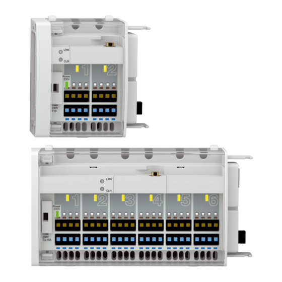
Transport und Lagerung Transport und Lagerung Das Produkt kann durch unsachgemäßen Transport und Lagerung beschä- digt werden. HINWEIS BESCHÄDIGUNG DES PRODUKTS • Stellen Sie sicher, dass während des Transports und der Lagerung des Pro- dukts die spezifizierten Umgebungsbedingungen eingehalten werden. •... - Page 7 Produktbeschreibung Produktbeschreibung Übersicht A. Reglermodul „F2“ 1. Anlerntasten (LRN-Taste) B. Reglermodul „F6“ 2. Verriegelung C. Abschlusskappe 3. Betrieb Netzspannung (LED grün) 4. Thermischer Stellantrieb aktiv (LED gelb) 5. Funkmodul 6. Anschlussleiste für thermische Stellantriebe 7. Sicherungsfach 8. Resettaste (CLR-Taste) F2 / F6 / F2A / F6A...
- Page 8 Produktbeschreibung Abmessungen (95) mm (182) mm 24 mm 162 mm 73 mm Anwendungsbeispiel(e) Abbildung 1: Basismodul mit Reglermodul, Uhrmodul, Raumfühlern, externer Antenne und Stellantrieben F2 / F6 / F2A / F6A...
- Page 9 Produktbeschreibung Funktion Die CosiTherm® ist eine Einzelraum-Temperaturregelung und regelt die Temperatur von Räumen mit Fußbodenheizung (Heizen/Kühlen). Das Pro- dukt ist ein Teil der CosiTherm®. Das Produkt mit je 2 oder 6 unabhängigen Regelkreisen steuern die Thermi- schen Stellantriebe über die Signale der Raumfühler und des Basismoduls. Es können mehrere Produkte mit jeweils 2 oder 6 Regelkreisen aneinander montiert werden.
- Page 10 Produktbeschreibung Technische Daten Parameter Allgemeine Daten Abmessungen (B x H x T) 73 x 92 x 45 mm 162 x 92 x 45 mm Gewicht 130 g 260 g Werkstoff Gehäuse PC/ABS Temperatureinsatzbereich Umgebung -20/+60 °C Lagerung -20/+60 °C Max. Luftfeuchtigkeit nicht kondensierend Spannungsversorgung Nennspannung...
-
Page 11: Montage
Montage Montage Produkt montieren Stellen Sie sicher, dass das Basismodul spannungsfrei ist. 1. Öffnen Sie die Abdeckung mit Hilfe eines Schraubendrehers. 2. Ziehen Sie die Abschlusskappe 3. Verbinden Sie das Produkt mit dem Basismodul und sichern bei- des mit der Verriegelung. F2 / F6 / F2A / F6A... - Page 12 Montage 4. Setzten Sie die Abschlusskappe auf das letzte Reglermodul. 5. Hängen Sie die Abdeckung ein und schliessen diese. F2 / F6 / F2A / F6A...
- Page 13 Montage Elektrischer Anschluss GEFAHR ELEKTRISCHER SCHLAG • Stellen Sie sicher, dass durch die Art der elektrischen Installation der Schutz gegen elektrischen Schlag (Schutzklasse, Schutzisolierung) nicht vermin- dert wird. Nichtbeachtung dieser Anweisungen führt zu Tod oder schweren Verlet- zungen. GEFAHR ELEKTRISCHER SCHLAG DURCH SPANNUNGSFÜHRENDE TEILE •...
- Page 14 Montage 5.2.1 Thermische Stellantriebe anschließen 1. Führen Sie das Kabel der Thermi- schen Stellantriebe durch die Zugentlastung (A) und schliessen Sie die Adern farbgleich an. 2. Stecken Sie die abisolierten Adern bis zum Anschlag in die Klemme. 3. Bei flexiblen Litzen oder zum Lösen der Klemmverbindung drü- cken Sie den Lösehebel (B).
- Page 15 Montage 5.2.2 Kabelklemme anbringen 1. Fixieren Sie das Kabel auf der Rückseite des Produkts mit der Kabelklemme (A). Wenn Raum- fühler mit Drahtanschluss einge- setzt werden, bringen Sie die Kabelklemme erst nach dem elek- trischen Anschluss des Raumfüh- ler an. F2 / F6 / F2A / F6A...
- Page 16 Montage 2. Verfahren Sie mit allen weiteren Kabeln gleich. 3. Die Kabelklemmen können auch wieder gelöst werden. Heben Sie die beiden Laschen (B) nach außen an und nehmen die Kabel- klemme ab. Module auf Hutschiene montieren Stellen Sie sicher, dass alle Module (Basis- und Reglermodul) zusam- mengesteckt und fest verriegelt sind.
- Page 17 Montage Module von der Hutschiene abnehmen 1. Heben Sie die Module (Basis- und Reglermodul) leicht an und nei- gen Sie sie oben von der Hut- schiene weg. 2. Nehmen Sie die Module (Basis- und Reglermodul) nach unten weg. F2 / F6 / F2A / F6A...
- Page 18 Montage Externe Antenne montieren HINWEIS BESCHÄDIGUNG DES PRODUKTS DURCH ELEKTROSTATISCHE ENTLADUNG • Erden Sie sich immer, bevor Sie die elektronischen Bauteile berühren. • Berühren Sie beim Einsetzen nicht das Produkt, sondern setzen Sie es mit Hilfe der anti-elektrostatischen Folie in den Steckplatz ein. Nichtbeachtung dieser Anweisungen kann zu Sachschäden führen.
- Page 19 Montage 5.5.1 Klebe-Antenne Leistungsgewinn: 2 dbi 1. Öffnen/entfernen Sie die Abde- ckung des Verteilerschranks. 2. Bohren Sie mit einer Bohrma- schine ein Loch in die Innenseite des Verteilerschranks. 3. Ziehen Sie das Kabel durch das gebohrte Loch und schrauben Sie den Anschluss der Klebe- Antenne am Funkmodul an.
- Page 20 Inbetriebnahme Inbetriebnahme Produkt in Betrieb nehmen Stellen Sie sicher, dass die Module ordnungsgemäß angeschlossen sind. Stellen Sie sicher, dass das Produkt korrekt an der Hutschiene fixiert ist. 1. Schalten Sie die Netzspannung ein. - Die grünen LEDs für den Betrieb des Basismoduls und des Produkts leuchten.
- Page 21 Inbetriebnahme 6.2.2 Einlernen 1. Drücken Sie die LRN-Taste des Produkts mit der Spitze des Kugelschreibers so lange (für mindestens 0,5 Sekunden), bis die gelbe LED Regelkreis 1 beginnt im Sekundentakt zu blin- ken. 2. Drücken Sie innerhalb der nächs- ten 30 Sekunden die LRN-Taste des Raumfühlers „FT / FTF“...
- Page 22 Inbetriebnahme 7. Nun stehen wieder 30 Sekunden zur Verfügung, um die LRN-Taste des nächsten Raumfühlers „FT / FTF“ zu drücken. 8. Wenn alle Regelkreise (1 bis 2, oder 1 bis 6) eines Produkts ein- gelernt sind, wechselt das Pro- dukt wieder in den regulären Betriebsmodus.
- Page 23 Inbetriebnahme 6.2.4 Abschluss 1. Bringen Sie die Abdeckung des Produkts an und schließen diese. 2. Bringen Sie die Raumfühler „FT / FTF“ in den vorgesehenen Räumen an. Beachten Sie dabei die korrekte Zuordnung Raumfühler / Regel- kreis / Raum. Funktionsprüfung Raumfühler „FT / FTF“...
-
Page 24: Betrieb
Betrieb Betrieb Übersicht der LED-Signale Anzeige Zustand Erklärung Betrieb Leuchtet Wenn Netzspannung für die Thermischen AC 230 V Stellantriebe vorhanden ist. (LED grün) Erlischt Bei Ausfall der Netzspannung. Bei Ausfall der Sicherung im Basismodul. Bei Ausfall der Sicherung (1). LED gelb Leuchtet Wenn der an diesen Regelkreis ange- schlossene Raumfühler „D / FT / FTF“... -
Page 25: Wartung
Sicherung defekt Prüfen Sie die Siche- rung Sonstige Störungen Netzteil defekt Bitte wenden Sie sich an die AFRISO-Service Hotline Außerbetriebnahme und Entsorgung Entsorgen Sie das Produkt nach den geltenden Bestimmungen, Normen und Sicherheitsvorschriften. Elektronikteile dürfen nicht mit dem Hausmüll entsorgt werden. -
Page 26: Gewährleistung
Vor einer Rücksendung Ihres Produkts müssen Sie sich mit uns in Verbin- dung setzen. Gewährleistung Informationen zur Gewährleistung finden Sie in unseren Allgemeinen Geschäftsbedingungen im Internet unter www.afriso.com oder in Ihrem Kauf- vertrag. Ersatzteile und Zubehör HINWEIS BESCHÄDIGUNG DURCH UNGEEIGNETE TEILE •... -
Page 27: Ersatzteile Und Zubehör
Ersatzteile und Zubehör Ersatzteile und Zubehör Artikelbezeichnung Art.-Nr. Abbildung Klebe-Antenne 78175 Magnetfuß-Antenne 78167 Antenne SMA-Winkelste- 78168 cker und Koaxialkabel F2 / F6 / F2A / F6A... - Page 28 Funkstandard • Funktechnologie • AN001 • AN102 • AN103 14.3 Möglichkeiten der EnOcean®-Technologie Unterlagen über EnOcean®-Technologien finden Sie im Internet unter www.afriso.de/afrisolab. Auf unserem YouTube-Channel finden Sie eine Reihe von Videos zu AFRISO-Produkten. F2 / F6 / F2A / F6A...
- Page 29 Operating instructions Controller module (wireless) Product family CosiTherm® Type: F2 Type: F6 Type: F2A Type: F6A Copyright 2015 AFRISO-EURO-INDEX GmbH. All rights reserved. Lindenstraße 20 74363 Güglingen Telefon+49 7135 102-0 Service+49 7135-102-211 Telefax +49 7135-102-147 info@afriso.com Version: 02.2016.0 www.afriso.com ID: 900.000.0710...
- Page 30 About these operating instructions About these operating instructions These operating instructions describe the controller module (wireless) „F2 / F6 / F2A / F6A" (also referred to as "product" in these operating instruc- tions). These operating instructions are part of the product. •...
-
Page 31: Information On Safety
Information on safety Information on safety Safety messages and hazard categories These operating instructions contain safety messages to alert you to poten- tial hazards and risks. In addition to the instructions provided in these opera- ting instructions, you must comply with all directives, standards and safety regulations applicable at the installation site of the product. - Page 32 Information on safety Intended use This product may only be used to control the temperature in single rooms with an underfloor heating system (heating/cooling). The controller module is a part of CosiTherm® and may only be used to con- trol the thermal actuators via the signals of the room temperature sensors and the base module.
- Page 33 Information on safety Qualification of personnel Only appropriately trained persons who are familiar with and understand the contents of these operating instructions and all other pertinent product docu- mentation are authorized to work on and with this product. These persons must have sufficient technical training, knowledge and expe- rience and be able to foresee and detect potential hazards that may be cau- sed by using the product.
-
Page 34: Transport And Storage
Transport and storage Transport and storage The product may be damaged as a result of improper transport or storage. NOTICE DAMAGE TO THE PRODUCT • Verify compliance with the specified ambient conditions during transport or storage of the product. • Use the original packaging when transporting the product. -
Page 35: Product Description
Product description Product description Overview A. Controller module „F2“ 1. Teach-in key (LRN key) B. Controller module „F6“ 2. Catch C. End cover 3. Operation mains voltage (LED green) 4. Thermal actuator active (LED yel- low) 5. Wireless module 6. Terminal block for thermal actu- ators 7. - Page 36 Product description Dimensions (95) mm (182) mm 24 mm 162 mm 73 mm Application example(s) Abbildung 1: Base module with controller module, timer module, room temperature sensors, external antenna and actuators F2 / F6 / F2A / F6A...
- Page 37 Product description Function CosiTherm® is a single room temperature controller used to control the tem- perature in rooms with underfloor heating system (heat/cool). The controller module is a part of CosiTherm®. The product with 2 or 6 independent control circuits control the thermal actu- ators via the signals of the room temperature sensors and the base module.
- Page 38 Product description Technical specifications Parameter General specifications Dimensions (W x H x D) 73 x 92 x 45 mm 162 x 92 x 45 mm Weight 130 g 260 g Housing material PC/ABS Operating temperature range Ambient -20/+60 °C Storage -20/+60 °C Max.
- Page 39 Mounting Mounting Mounting the product Verify that the base module is disconnected from mains. 1. Open the cover using a screwdri- ver. 2. Pull off the end cover. 3. Connect the product to the base module and secure the connec- tion with the catch.
- Page 40 Mounting 4. Refit the end cover onto the last controller module. 5. Refit the cover and close it. F2 / F6 / F2A / F6A...
- Page 41 Mounting Electrical connection DANGER ELECTRIC SHOCK • Verify that the degree of protection against electric shock (protection class II, double insulation) is not reduced by the type of electrical installation. Failure to follow these instructions will result in death or serious injury. DANGER ELECTRIC SHOCK CAUSED BY LIVE PARTS •...
- Page 42 Mounting 5.2.1 Connecting the thermal actuators 1. Route the cables of the thermal actuators through the strain reliefs (A) and connect the wires to the corresponding terminals (observe colour coding). 2. Push the stripped wires all the way into the terminals. 3.
- Page 43 Mounting 5.2.2 Fitting the cable clamp 1. Fix the cable at the rear of the pro- duct using the cable clamp (A). If room temperature sensors with a wired connection are used, first make the electrical connection of the room temperature sensors and then fit the cable clamp.
- Page 44 Mounting 2. Repeat this procedure for all other cables. 3. It is possible to open the cable clamps. To do so, pull the two tabs (B) outwards and remove the cable clamp. Mounting modules on a DIN rail Verify that all modules (base module and controller modules) are plugged together and firmly locked.
- Page 45 Mounting Removing modules from a DIN rail 1. Slightly lift the modules (base module and controller modules) and tilt the top away from the DIN rail. 2. Remove the modules (base module and controller modules) towards the bottom. F2 / F6 / F2A / F6A...
- Page 46 Mounting Mounting an external antenna NOTICE DAMAGE TO THE PRODUCT DUE TO ELECTROSTATIC DISCHARGE • Always earth yourself before touching electronic components. • Do not touch the product to plug it in; use the anti-electrostatic film to plug the product into the slot. Failure to follow these instructions can result in equipment damage.
- Page 47 Mounting 5.5.1 Adhesive antenna Transmission power gain: 2 dbi 1. Open/remove the cover of the cabinet. 2. Drill a hole into the inside of the cabinet using a power drill. 3. Route the cable through the dril- led hole and screw the connection of the adhesive antenna to the wireless module.
- Page 48 Commissioning Commissioning Commissioning the product Verify that the modules are properly connected. Verify that the product is properly mounted to the DIN rail. 1. Apply mains voltage. - The green LEDs (operation) of the base module and of the product light Connecting room temperature sensors „FT / FTF“...
- Page 49 Commissioning 6.2.2 Teaching in 1. Press the LRN key of the product with the tip of the ballpoint pen (for at least 0.5 seconds) until the yel- low LED for control circuit 1 starts flashing at intervals of one second. 2.
- Page 50 Commissioning 7. You now have an additional 30 seconds to press the LRN key of the next room temperature sen- sor „FT / FTF“. 8. Once you have taught in all cont- rol circuits (1 to 2, or 1 to 6) of a product, the product switches back to normal operating mode.
- Page 51 Commissioning 6.2.4 Terminating 1. Refit the cover of the product and close it. 2. Install the room temperature sensors „FT / FTF“ in the appropriate rooms. Observe the assignment room temperature sensor/control cir- cuit/room when doing so. Function test Room temperature sensor „FT / FTF“ ...
-
Page 52: Operation
Operation Operation Overview of the LED signals Display State Explanation Operation Solid lit When mains voltage for the thermal actu- AC 230 V ators is applied. (LED green) Goes off In the case of power failure. If the fuse in the base module trips. If the fuse (1) trips. -
Page 53: Maintenance
(green LED) tage Fuse defective Check the fuse Other malfunctions Power supply unit defec- Contact the AFRISO tive service hotline Decommissioning, disposal Dispose of the product in compliance with all applicable directives, standards and safety regulations. Electronic components must not be disposed of together with the normal household waste. -
Page 54: Returning The Device
Returning the device Returning the device Get in touch with us before returning your product. Warranty See our terms and conditions at www.afriso.com or your purchase contract for information on warranty. Spare parts and accessories NOTICE DAMAGE DU TO UNSUITABLE PARTS •... -
Page 55: Spare Parts And Accessories
Spare parts and accessories Spare parts and accessories Product designation Part no. Figure Adhesive antenna 78175 Magnetic foot antenna 78167 Antenna angular SMA 78168 connector and coaxial cable F2 / F6 / F2A / F6A... - Page 56 • AN102 • AN103 14.3 Features of the EnOcean® technology Visit www.afriso.de/afrisolab for documents on EnOcean® technologies. A variety of videos on AFRISO products can also be found on the AFRISO YouTube channel. F2 / F6 / F2A / F6A...
- Page 57 Instrukcja eksploatacji Moduł sterujący (bezprzewodowy) System CosiTherm® Typ: F2 Typ: F6 Typ: F2A Typ: F6A Copyright 2015 AFRISO-EURO-INDEX GmbH. Wszystkie prawa zastrzeżone. Lindenstraße 20 74363 Güglingen telefon +49 7135-102-0 serwis +49 7135-102-211 telefaks +49 7135-102-147 info@afriso.com Wersja: 02.2016.0 www.afriso.com ID: 900 000.0710...
- Page 58 Objaśnienia do niniejszej instrukcji eksploatacji Objaśnienia do niniejszej instrukcji eksploatacji Niniejsza instrukcja eksploatacji opisuje moduł sterujący (bezprzewodowy) „F2/F6/F2A/F6A“ (poniżej zwany także „produktem“). Niniejsza instrukcja eksploatacji jest częścią produktu. • Produkt wolno użytkować dopiero po całkowitym przeczytaniu i pełnym zrozumieniu instrukcji eksploatacji. •...
- Page 59 Informacje na temat bezpieczeństwa Informacje na temat bezpieczeństwa Wskazówki ostrzegawcze i klasy zagrożenia Niniejsza instrukcja eksploatacji zawiera wskazówki ostrzegawcze zwraca- jące uwagę na potencjalne zagrożenia oraz ryzyka. Poza zaleceniami zawar- tymi w niniejszej instrukcji eksploatacji trzeba przestrzegać wszystkich warunków, norm oraz przepisów bezpieczeństwa obowiązujących w miej- scu użytkowania produktu.
- Page 60 Informacje na temat bezpieczeństwa Ten symbol ostrzega przed niebezpiecznym napięciem elektrycznym. O ile symbol ten pojawia się we wskazówce ostrzegawczej, zachodzi niebezpieczeństwo porażenia prądem elektrycznym. Stosowanie zgodne z przeznaczeniem Ten produkt przeznaczony jest wyłącznie do regulacji temperatury pokojo- wej w pomieszczeniach z ogrzewaniem podłogowym (grzanie / chłodzenie). Moduł...
- Page 61 Informacje na temat bezpieczeństwa Przewidywalne błędne stosowanie Produktu nie wolno stosować w szczególności w następujących przypad- kach i do następujących celów: • otoczenie zagrożone wybuchem; - w razie eksploatacji w strefach zagrożonych wybuchem iskrzenie może doprowadzić do wyfuknięcia, pożaru lub eksplozji, •...
- Page 62 Transport i składowanie Transport i składowanie Niewłaściwy transport i składowanie mogą spowodować uszkodzenie pro- duktu. WSKAZÓWKA USZKODZENIE PRODUKTU • Należy upewnić się, że podczas transportu i składowania produktu dotrzy- mywane są warunki otoczenia wyszczególnione w specyfikacji. • Do celów transportowych należy wykorzystywać oryginalne opakowanie. •...
- Page 63 Opis produktu Opis produktu Przegląd A. moduł sterujący F2 1. przyciski programowania (przy- cisk LRN) B. moduł sterujący F6 2. zatrzask C. pokrywka zamykająca 3. włączone napięcie sieciowe (zie- lona dioda LED) 4. siłownik termoelektryczny włącz- ony (żółta dioda LED) 5.
- Page 64 Opis produktu Wymiary (95) mm (182) mm 24 mm 162 mm 73 mm Przykład(y) zastosowania Abbildung 1: Moduł podstawowy z modułem sterującym, modułem czasowym, czu- jnikami pokojowymi, anteną zewnętrzną i siłownikami Moduł sterujący (bezprzewodowy)
- Page 65 Opis produktu Działanie System CosiTherm® jest to regulator temperatury pokojowej służący do regulacji temperatury w pomieszczeniach z ogrzewaniem podłogowym (grzanie / chłodzenie). Moduł sterujący jest częścią systemu CosiTherm®. Produkt zawierający po 2 lub 6 niezależnych obwodów regulacji steruje siłownikami termoelektrycznymi za pośrednictwem sygnałów pochod- zących z czujników pokojowych oraz modułu podstawowego.
- Page 66 Opis produktu Dane techniczne Parametr Dane ogólne wymiary z izolacją 73 x 92 x 45 mm 162 x 92 x 45 mm (szerokość x wysokość x gł ębokość) waga 130 g 260 g materiał korpusu poliwęglan PC / kopolimer akrylonitrylo- butadieno-styrenowy ABS Dopuszczalny zakres temperatur otoczenie...
- Page 67 Opis produktu Parametr Kompatybilność elektromagnetyczna (EMC) (2004/108/WE) emisja zakłóceń / odpor- EN 61326-1: 2006-10 ność na zakłócenia n® Technologia bezprzewodowa EnOcea dyrektywa telekomunikacy- EN 301489-3, EN 300220-1, EN 300220-2, jna 1999/5/WE EN 62479:2010 Moduł sterujący (bezprzewodowy)
- Page 68 Montaż Montaż Montaż produktu Należy upewnić się, że moduł podstawowy nie znajduje się pod napię- ciem. 1. Otworzyć osłonę za pomocą śru- bokręta. 2. Zdjąć pokrywkę przyłącza. 3. Połączyć produkt z modułem podstawowym i zabezpieczyć zatrzaskiem oba urządzenia. Moduł sterujący (bezprzewodowy)
- Page 69 Montaż 4. Nasunąć pokrywkę zamykającą na ostatni moduł sterujący. 5. Zamocować i zamknąć osłonę. Moduł sterujący (bezprzewodowy)
- Page 70 Montaż Przyłącze elektryczne NIEBEZPIECZEŃSTWO PORAŻENIE PRĄDEM ELEKTRYCZNYM • Należy upewnić się, że rodzaj instalacji elektrycznej nie zmniejsza zakresu ochrony przed porażeniem prądem elektrycznym (klasa ochronności, izo- lacja ochronna). Nieprzestrzeganie niniejszych zaleceń prowadzi do śmierci lub poważnych obrażeń. NIEBEZPIECZEŃSTWO PORAŻENIE PRĄDEM ELEKTRYCZNYM PRZEZ ELEMENTY ZNAJDU- JĄCE SIĘ...
- Page 71 Montaż 5.2.1 Podłączenie siłowników termoelektrycznych 1. Przeprowadzić przewód siłow- ników termoelektrycznych przez uchwyt odciążający zabezpiecza- jący przed zerwaniem i podłączyć żyły zgodnie z kolorami. 2. Żyły z usuniętą izolacją wsunąć do zacisku do oporu. W przy- padku elastycznych przewodów licowych lub w celu poluzowania złącza zaciskowego wcisnąć...
- Page 72 Montaż 5.2.2 Mocowanie opaski na przewodzie 1. Przymocować przewód po tylnej stronie produktu za pomocą opaski (1). W razie stosowania przewodowych czujników poko- jowych opaskę zamocować dopi- ero po wykonaniu podłączenia elektrycznego czujników. Moduł sterujący (bezprzewodowy)
- Page 73 Montaż 2. Powtórzyć czynność dla wszyst- kich przewodów. 3. Opaski dają się ponownie zde- montować. W tym celu podważyć oba piórka (2) w kierunku zewnętrznym i zdjąć opaskę. Montaż modułów na szynie montażowej DIN Należy upewnić się, że wszystkie moduły (moduł podstawowy i moduł sterujący) są...
- Page 74 Montaż Demontaż modułów z szyny montażowej DIN 1. Lekko unieść moduły (moduł podstawowy i moduł sterujący) i odchylić ich górną część od szyny montażowej DIN. 2. Zdjąć moduły (moduł podsta- wowy i moduł sterujący), pocią- gając je w kierunku dolnym. Moduł...
- Page 75 Montaż Montaż anteny zewnętrznej WSKAZÓWKA USZKODZENIE PRODUKTU PRZEZ ELEKTROSTATYCZNE WYŁADOWANIA • Przed dotknięciem elektronicznych elementów układu zawsze konieczne jest wcześniejsze uziemienie osoby wykonującej obsługę. • Podczas montażu nie dotykać produktu, instalując go w gnieździe wty- kowym przy pomocy folii antystatycznej. Nieprzestrzeganie niniejszych zaleceń...
- Page 76 Montaż 5.5.1 Antena klejona Zysk energetyczny anteny: 2 dbi. 1. Otworzyć / usunąć osłonę szafki rozdzielczej. 2. Przy pomocy wiertarki przewier- cić otwór do wnętrza szafki rozd- zielczej. 3. Przez przewiercony otwór prze- ciągnąć przewód i przykręcić przyłącze anteny klejonej do modułu bezprzewodowego.
- Page 77 AFRISOhome Gateway. Bramka AFRISOhome Gateway musi znajdować się w „trybie progra- mowania“. Szczegółowe informacje dotyczące programowania / kaso- wania są opisane w instrukcji eksploatacji bramki sieciowej AFRISO- home Gateway. Należy upewnić się, że tylna strona przewidzianych do zaprogramowa- nia czujników pokojowych FT/FTF jest kolejno ponumerowana i oznac- zona odnośną...
- Page 78 Uruchomienie 6.2.2 Programowanie 1. Ostrym końcem długopisu wcis- kać przycisk LRN produktu tak długo (przez okres co najmniej 0,5 sekundy), aż żółta dioda LED obwodu regulacji 1 zacznie migać w takcie sekundowym. 2. W ciągu kolejnych 30 sekund wcisnąć przycisk LRN czujnika pokojowego FT/FTF obwodu regulacji 1 (na okres co najmniej 0,5 sekundy), posługując się...
- Page 79 Uruchomienie 7. Wtedy kolejnych 30 sekund jest przewidzianych na wciśnięcie przycisku LNR następnego czuj- nika pokojowego FT/FTF. 8. Po zaprogramowaniu wszystkich obwodów regulacji (1 do 2 lub 1 do 6) danego produktu włącza się ponownie regularny tryb pracy produktu. 9. Jeśli w trybie programowania (żółta dioda LED obwodu regu- lacji miga w takcie sekundowym) żaden przycisk LRN czujnika...
- Page 80 Uruchomienie 6.2.4 Zakończenie 1. Zamocować i zamknąć osłonę produktu. 2. Czujniki pokojowe FT/FTF zainstalować w przewidzianych pomieszcze- niach. Podczas tych czynności przestrzegać prawidłowego przyporząd- kowania czujnika pokojowego / obwodu regulacji / pomieszczenia. Kontrola działania Czujniki pokojowe FT/FTF Należy upewnić się, że temperatura w pomieszczeniu utrzymuje się w granicach od 15 °C do 25 °C.
- Page 81 Eksploatacja Eksploatacja Przegląd sygnałów diod LED Wskaźnik Stan Objaśnienie tryb pracy świeci się jeśli napięcie sieciowe jest podłączone do AC 230 V siłowników termoelektrycznych (zielona gaśnie w razie zaniku napięcia sieciowego, dioda LED) w razie uszkodzenia bezpiecznika w module podstawowym, w razie uszkodzenia bezpiecznika (1) żółta dioda świeci się...
- Page 82 LED) sygnalizacja włączo- brak napięcia siecio- sprawdzić układ zasila- nego napięcia 5 V nie wego świeci się (zielona dioda uszkodzony bezpiecz- sprawdzić bezpiecznik LED) pozostałe zakłócenia uszkodzony zasilacz proszę skontaktować się z infolinią serwisową AFRISO Moduł sterujący (bezprzewodowy)
- Page 83 2. Wykonać demontaż produktu (patrz rozdział Montaż w odwrotnej kolejności). 3. Produkt poddać utylizacji. Zwrot Przed zwrotną wysyłką produktu wymagany jest kontakt z producentem. Gwarancja Informacje dotyczące gwarancji są dostępne w naszych Ogólnych Warunkach Handlowych w internecie pod adresem www.afriso.com lub w umowie kupna. Moduł sterujący (bezprzewodowy)
- Page 84 Części zamienne i wyposażenie dodatkowe Części zamienne i wyposażenie dodatkowe WSKAZÓWKA USZKODZENIE SPOWODOWANE PRZEZ STOSOWANIE NIEWŁAŚCI- WYCH CZĘŚCI • Należy stosować wyłącznie oryginalne części zamienne i wyposażenie dodatkowe producenta. Nieprzestrzeganie niniejszego zalecenia może doprowadzić do powstania szkód materialnych. Produkt Nazwa artykułu Numer artykułu Ilustracja moduł...
- Page 85 Części zamienne i wyposażenie dodatkowe Części zamienne i wyposażenie dodatkowe Nazwa artykułu Numer artykułu Ilustracja antena klejona 78175 antena z podstawką magn- 78167 etyczną antena, złącze kątowe 78168 SMA i kabel koncentryczny Moduł sterujący (bezprzewodowy)
- Page 86 • AN001, • AN102, • AN103. 13.3 Możliwości technologii EnOcean® Informacje o zastosowaniach technologicznych systemu EnOcean® znaj- dują się w internecie na stronie www.afriso.de/afrisolab. Zestaw filmów wideo na temat produktów AFRISO znajduje się na kanale YouTube firmy AFRISO. Moduł sterujący (bezprzewodowy)
Need help?
Do you have a question about the CosiTherm F2 and is the answer not in the manual?
Questions and answers