Table of Contents
Advertisement
Available languages
Available languages
Quick Links
Advertisement
Table of Contents

Related Manuals for AFRISO CosiTherm WB 10 D8-230


Summary of Contents for AFRISO CosiTherm WB 10 D8-230
- Page 1 Betriebsanleitung Operating instructions Notice technique Klemmleiste Basic (Draht) Basic controller terminal bar (wired) Bornier de commande Basic (filaire) Copyright 2023 AFRISO-EURO-INDEX GmbH. Alle Rechte vorbehalten. Version: 12.2023.0 ID: 900.000.1086...
- Page 2 Betriebsanleitung Basic Klemmleiste (Draht) Produktfamilie CosiTherm® Typ: WB 10 D8-230 Copyright 2023 AFRISO-EURO-INDEX GmbH. Alle Rechte vorbehalten. Version: 12.2023.0 ID: 900.000.1086...
-
Page 3: Über Diese Betriebsanleitung
Über diese Betriebsanleitung Über diese Betriebsanleitung Diese Betriebsanleitung beschreibt die (Basic) Klemmleiste WB 10 D8-230 (im Folgenden auch „Produkt“). Diese Betriebsanleitung ist Teil des Produkts. • Sie dürfen das Produkt erst benutzen, wenn Sie die Betriebsanleitung vollständig gelesen und verstanden haben. •... - Page 4 Informationen zur Sicherheit Informationen zur Sicherheit Warnhinweise und Gefahrenklassen In dieser Betriebsanleitung finden Sie Warnhinweise, die auf potenzielle Gefahren und Risiken aufmerksam machen. Zusätzlich zu den Anweisungen in dieser Betriebsanleitung müssen Sie alle am Einsatzort des Produktes geltenden Bestimmungen, Normen und Sicherheitsvorschriften beachten. Stellen Sie vor Verwendung des Produkts sicher, dass Ihnen alle Bestimmun- gen, Normen und Sicherheitsvorschriften bekannt sind und dass sie befolgt werden.
-
Page 5: Informationen Zur Sicherheit
Informationen zur Sicherheit Bestimmungsgemäße Verwendung Dieses Produkt eignet sich ausschließlich zur Verdrahtung der Raumther- mostate und der thermischen Stellantriebe. Über das Produkt werden die Stellantriebe und die Raumthermostate mit Spannung versorgt. Eine andere Verwendung ist nicht bestimmungsgemäß und verursacht Gefahren. Stellen Sie vor Verwendung des Produkts sicher, dass das Produkt für die von Ihnen vorgesehene Verwendung geeignet ist. - Page 6 Informationen zur Sicherheit Vorhersehbare Fehlanwendung Das Produkt darf insbesondere in folgenden Fällen und für folgende Zwecke nicht angewendet werden: • Explosionsgefährdete Umgebung - Bei Betrieb in explosionsgefährdeten Bereichen kann Funkenbildung zu Verpuffungen, Brand oder Explosionen führen. • In Verbindung mit Produkten, die direkt oder indirekt menschlichen, gesundheits- oder lebenssichernden Zwecken dienen, oder durch deren Betrieb Gefahren für Mensch, Tier oder Sachwerte entstehen können.
-
Page 7: Transport Und Lagerung
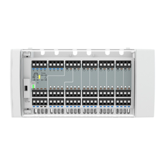
Transport und Lagerung Transport und Lagerung Das Produkt kann durch unsachgemäßen Transport und Lagerung beschä- digt werden. HINWEIS UNSACHGEMÄSSE HANDHABUNG • Stellen Sie sicher, dass während des Transports und der Lagerung des Pro- dukts die spezifizierten Umgebungsbedingungen eingehalten werden. • Benutzen Sie für den Transport die Originalverpackung. - Page 8 Produktbeschreibung Produktbeschreibung Übersicht A. Betrieb Versorgungsspannung (LED grün) B. Pumpe aktiv (LED gelb) C. Anschlussleiste für Raumthermostate D. Anschlussleiste für thermische Stellantriebe E. Anschlussklemmen Pumpe F. Versorgungsspannung AC 230 V G. Sicherungsfach Netzsicherung WB 10 D8-230...
- Page 9 Produktbeschreibung Abmessung 210 mm Abbildung 1: Abmessung Produkt Funktion Die CosiTherm® ist eine Einzelraum-Temperaturregelung und regelt die Temperatur von Räumen mit Fußbodenheizung. Das Produkt ist ein Teil der CosiTherm®. Das Produkt mit 8 unabhängigen Regelkreisen versorgt die Raumthermos- tate und die thermischen Stellantriebe mit Spannung. Das Raumthermostat schaltet über das Produkt die thermischen Stellantriebe und regelt damit den Heizkreis am Verteiler.
- Page 10 Produktbeschreibung Anwendungsbeispiel An das Produkt können bis zu 8 Raumthermostate und 20 Stellantriebe angeschlossen werden. Abbildung 2: Klemmleiste mit Raumthermostaten, Pumpe und thermischen Stellan- trieben Zulassungsdokumente, Bescheinigungen, Erklärungen Das Produkt entspricht: • EMV-Richtlinie (2014/30/EU) • Niederspannungsrichtlinie (2014/35/EU) • RoHS-Richtlinie (2011/65/EU) WB 10 D8-230...
- Page 11 Produktbeschreibung Technische Daten Parameter Wert Allgemeine Daten Abmessungen Gehäuse (B x H x T) 210 x 92 x 24 mm Gewicht 275 g Werkstoff Gehäuse PC/ABS An ein Produkt dürfen angeschlossen werden Raumthermostate Thermische Stellantriebe Umgebungsbedingungen Umgebungstemperatur Betrieb 5 ... 50 °C Umgebungstemperatur Lagerung -25 ...
-
Page 12: Montage
Montage Montage Elektrischer Anschluss GEFAHR ELEKTRISCHER SCHLAG • Stellen Sie sicher, dass durch die Art der elektrischen Installation der Schutz gegen elektrischen Schlag (Schutzklasse, Schutzisolierung) nicht vermindert wird. Nichtbeachtung dieser Anweisungen führt zu Tod oder schweren Verlet- zungen. GEFAHR ELEKTRISCHER SCHLAG DURCH SPANNUNGSFÜHRENDE TEILE •... - Page 13 Montage 5.1.1 Thermischen Stellantrieb anschließen 1. Führen Sie das Kabel des thermi- schen Stellantriebs durch die Zugentlastung (B). 2. Schließen Sie die Adern farbgleich 3. Stecken Sie die abisolierten Adern bis zum Anschlag in die Klemme. 4. Zum Lösen der Adern drücken Sie den Lösehebel (A).
- Page 14 Montage 5.1.3 Kabelklemme anbringen 1. Fixieren Sie das Kabel auf der Rückseite des Produkts mit der Kabelklemme (A). Bringen Sie die Kabelklemme erst nach dem elek- trischen Anschluss des Raum- thermostats an. WB 10 D8-230...
- Page 15 Montage 2. Verfahren Sie mit allen weiteren Kabeln gleich. 3. Die Kabelklemmen können auch wieder gelöst werden. Heben Sie die beiden Laschen (B) nach außen an und nehmen die Kabel- klemme ab. 5.1.4 Pumpe anschließen Über die Versorgungsspannung des Produkts 1.
- Page 16 Montage Über den potenzialfreien Ausgang des Produkts 1. Führen Sie das Kabel der Pumpe (A) durch die Zugentlas- tung. 2. Schließen Sie die Adern entspre- chend der Abbildung an. 3. Zum Lösen der Adern drücken Sie den Lösehebel. Abbildung 7: Pumpe über den potenzialfreien Ausgang des Produkts anschließen WB 10 D8-230...
- Page 17 Montage Produkt auf Hutschiene montieren Stellen Sie sicher, dass alle Kabel angeschlossen sind. 1. Setzten Sie das Produkt mit den oberen Haken in die Hutschiene ein. 2. Drücken Sie das Produkt unten in Richtung Hutschiene, bis es hörbar einrastet. Abbildung 8: Produkt auf Hutschiene montieren WB 10 D8-230...
- Page 18 Montage Produkt von der Hutschiene abnehmen 1. Heben Sie das Produkt leicht an. 2. Neigen Sie das Produkt oben von der Hutschiene weg. 3. Nehmen Sie das Produkt nach unten weg. Abbildung 9: Produkt von der Hutschiene abnehmen WB 10 D8-230...
- Page 19 Inbetriebnahme Inbetriebnahme Produkt in Betrieb nehmen Stellen Sie sicher, dass das Produkt ordnungsgemäß montiert und elekt- risch angeschlossen wurde. Stellen Sie sicher, dass das Produkt korrekt an der Hutschiene fixiert ist. Schalten Sie die Versorgungsspannung ein. - Die grüne LED des Produkts leuchtet. Funktionsprüfung durchführen Raumthermostat ...
-
Page 20: Betrieb
Betrieb Betrieb Übersicht der LED-Signale Abbildung 10: Übersicht der LED-Signale Anzeige Zustand Erklärung Betrieb Leuchtet Wenn Versorgungsspannung für die ther- AC 230 V mischen Stellantriebe und die Raumther- (LED grün) mostate vorhanden ist Erlischt Bei Ausfall der Versorgungsspannung Bei Ausfall der Sicherung Pumpe ... -
Page 21: Wartung
Sicherung defekt Prüfen Sie die Siche- rung Sonstige Störungen Bitte wenden Sie sich an die AFRISO-Service Hotline Sicherung tauschen Stellen Sie sicher, dass die Versorgungsspannung unterbrochen und gegen Wiedereinschalten gesichert ist. 1. Öffnen Sie die Abdeckung mit Hilfe eines Schraubendrehers. - Page 22 Störungsbeseitigung 2. Nehmen Sie den Sicherungshal- ter heraus. 3. Tauschen Sie die defekte Siche- rung gegen eine Sicherung des gleichen Typs. 4. Setzten Sie den Sicherungshalter in das Sicherungsfach ein. 5. Schließen Sie die Abdeckung. WB 10 D8-230...
-
Page 23: Außerbetriebnahme Und Entsorgung
3. Entsorgen Sie das Produkt. Rücksendung Vor einer Rücksendung Ihres Produkts müssen Sie sich mit uns in Verbin- dung setzen (service@afriso.de). Gewährleistung Informationen zur Gewährleistung finden Sie in unseren Allgemeinen Geschäftsbedingungen im Internet unter www.afriso.com oder in Ihrem Kauf- vertrag. WB 10 D8-230... -
Page 24: Ersatzteile Und Zubehör
Ersatzteile und Zubehör Ersatzteile und Zubehör Produkt Artikelbezeichnung Art.-Nr. Abbildung CosiTherm® Basic Klemm- 80236 leiste WB 10 D8-230 Ersatzteile und Zubehör Artikelbezeichnung Art.-Nr. Abbildung Raumthermostat RT 10 86062 D-230 Thermischer Stellantrieb 78882 TSA-02 Thermischer Stellantrieb 79016 TSA 02 FO WB 10 D8-230... - Page 25 Anhang Anhang 14.1 EU-Konformitätserklärung WB 10 D8-230...
- Page 26 Operating instructions Basic controller terminal bar (wired) Product family CosiTherm® Type: WB 10 D8-230 Copyright 2023 AFRISO-EURO-INDEX GmbH. All rights reserved. Version: 12.2023.0 ID: 900.000.1086...
- Page 27 About these operating instructions About these operating instructions These operating instructions describe the (basic) controller terminal bar WB 10 D8-230 (also referred to as "product" in these operating instructions). These operating instructions are part of the product. • You may only use the product if you have fully read and understood these operating instructions.
-
Page 28: Information On Safety
Information on safety Information on safety Safety messages and hazard categories These operating instructions contain safety messages to alert you to poten- tial hazards and risks. In addition to the instructions provided in these oper- ating instructions, you must comply with all directives, standards and safety regulations applicable at the installation site of the product. - Page 29 Information on safety Intended use This product may only be used for wiring the room thermostats and the ther- mostatic actuators. The product supplies the actuators and room thermo- stats. Any use other than the application explicitly permitted in these operating instructions is not permitted and causes hazards.
-
Page 30: Predictable Incorrect Application
Information on safety Predictable incorrect application The product must never be used in the following cases and for the following purposes: • Hazardous area - If the product is operated in hazardous areas, sparks may cause defla- grations, fires or explosions. •... -
Page 31: Transport And Storage
Transport and storage Transport and storage The product may be damaged as a result of improper transport or storage. NOTICE INCORRECT HANDLING • Verify compliance with the specified ambient conditions during transport or storage of the product. • Use the original packaging when transporting the product. •... - Page 32 Product description Product description Overview A. Operation supply voltage (LED green) B. Pump active (LED yellow) C. Terminal block for room thermostats D. Terminal block for thermostatic actuators E. Connection terminals for pump F. Supply voltage AC 230 V G. Fuse compartment mains fuse WB 10 D8-230...
-
Page 33: Product Description
Product description Dimensions 210 mm Fig. 1: Dimensions product Function CosiTherm® is a single room temperature controller used to control the tem- perature in rooms with underfloor heating system. The product is a part of CosiTherm®. The product with 8 independent control circuits supplies the room thermo- stats and the thermostatic actuators. -
Page 34: Application Example
Product description Application example Up to 8 room thermostats and 20 actuators can be connected to the product. Fig. 2: Controller terminal bar with room thermostats, pump and thermostatic actua- tors Approvals, conformities, certifications The product complies with: • EMC Directive (2014/30/EU) •... -
Page 35: Technical Specifications
Product description Technical specifications Parameter Value General specifications Dimensions housing (W x H x D) 210 x 92 x 24 mm Weight 275 g Housing material PC/ABS The following components may be connected to one product Room thermostats Thermostatic actuators Ambient conditions Ambient temperature operation 5 ... - Page 36 Mounting Mounting Electrical connection DANGER ELECTRIC SHOCK • Verify that the degree of protection against electric shock (protection class, double insulation) is not reduced by the type of electrical installation. Failure to follow these instructions will result in death or serious injury. DANGER ELECTRIC SHOCK CAUSED BY LIVE PARTS •...
- Page 37 Mounting 5.1.1 Connecting a thermostatic actuator 1. Route the cables of the thermo- static actuator through the strain relief (B). 2. Connect the wires (observe colour coding). 3. Push the stripped wires into the terminals all the way to the stop. 4.
- Page 38 Mounting 5.1.3 Fitting the cable clamp 1. Fix the cable at the rear of the product using the cable clamp (B). Connect the room ther- mostat before fitting the cable clamp. WB 10 D8-230...
- Page 39 Mounting 2. Repeat this procedure for all other cables. 3. It is possible to open the cable clamps. To do so, pull the two tabs (B) outwards and remove the cable clamp. 5.1.4 Connecting the pump Via the supply voltage of the product 1.
- Page 40 Mounting Via the voltage-free output of the product 1. Route the cable of the pump (A) through the strain relief. 2. Connect the wires as shown in the illustration. 3. Push the catch to disconnect the wires. Fig. 7: Connecting the pump via the voltage-free output of the product WB 10 D8-230...
- Page 41 Mounting Mounting the product on a DIN rail Verify that all cables are connected. 1. Fit the product into the DIN rail with the upper hooks. 2. Push the lower end of the product towards the DIN rail until it snaps in with a click.
- Page 42 Mounting Removing the product from the DIN rail 1. Slightly lift the product. 2. Tilt the top of the product away from the DIN rail. 3. Remove the product towards the bottom. Fig. 9: Removing the product from the DIN rail WB 10 D8-230...
-
Page 43: Commissioning The Product
Commissioning Commissioning Commissioning the product Verify that the product has been properly mounted and electrically con- nected. Verify that the product is properly mounted to the DIN rail. Switch on the supply voltage. - The green LED for the product lights. Performing the function test Room thermostat ... -
Page 44: Operation
Operation Operation Overview of the LED signals Fig. 10: Overview of the LED signals Indication State Explanation Operation Solid lit When supply voltage for the thermostatic AC 230 V actuators and the room thermostats is (LED green) applied Goes off In the case of power outage If the fuse trips Pump ... -
Page 45: Troubleshooting
(green LED) Fuse tripped Check the fuse Other malfunctions Contact the AFRISO service hotline Replacing the fuse Verify that the supply voltage is interrupted and cannot be switched on. 1. Open the cover using a screw- driver. - Page 46 Troubleshooting 3. Replace the defective fuse with a fuse of the same type. 4. Insert the fuse holder into the fuse compartment. 5. Close the cover. WB 10 D8-230...
-
Page 47: Decommissioning / Disposal
3. Dispose of the product. Returning the device Get in touch with us before returning your product (service@afriso.de). Warranty See our terms and conditions at www.afriso.com or your purchase contract for information on warranty. WB 10 D8-230... -
Page 48: Spare Parts And Accessories
Spare parts and accessories Spare parts and accessories Product Product designation Part no. Figure CosiTherm® Basic control- 80236 ler terminal bar WB 10 D8-230 Spare parts and accessories Product designation Part no. Figure Room thermostat RT 10 86062 D-230 Thermostatic actuator 78882 TSA-02 Thermostatic actuator TSA... - Page 49 Appendix Appendix 14.1 EU Declaration of Conformity WB 10 D8-230...
- Page 50 Notice technique Bornier de commande Basic (filaire) Famille de produits CosiTherm® Type : WB 10 D8-230 Copyright 2023 AFRISO-EURO-INDEX GmbH. Tous droits réservés. Version: 12.2023.0 ID: 900.000.1086...
- Page 51 La présente notice technique La présente notice technique Cette notice technique contient la description du bornier de commande (Basic) WB 10 D8-230 (dénommé ci-après "produit"). Cette notice technique fait partie du produit. • Utilisez le produit seulement après que vous aurez lu et compris intégra- lement la notice technique.
- Page 52 Informations sur la sécurité Informations sur la sécurité Consignes de sécurité et classes de risques Cette notice technique contient des consignes de sécurité destinées à attirer l'attention sur les dangers et les risques. Outre les instructions contenues dans cette notice technique, il faut vous assurer de l'observation de tous les règlements, normes et consignes de sécurité...
-
Page 53: Informations Sur La Sécurité
Informations sur la sécurité Usage normal Le produit est destiné exclusivement au câblage des thermostats d'ambiance et des actionneurs thermiques. Le produit alimente les action- neurs et les thermostats d'ambiance. Toute autre utilisation n'est pas conforme et cause des risques. Avant d'utiliser le produit, assurez-vous que le produit est adapté... - Page 54 Informations sur la sécurité Utilisation non conforme prévisible Le produit ne doit, en particulier, pas être utilisé dans les cas suivants : • Dans des zones à risque d'explosion - En cas de service dans des atmosphères explosibles, des étincelles peuvent provoquer des déflagrations, des incendies ou des explosions.
-
Page 55: Transport Et Stockage
Transport et stockage Transport et stockage Un transport et un stockage inadéquats risquent de causer des dommages au produit. AVIS MANUTENTION INAPPROPRIÉE • Assurez-vous que les conditions ambiantes spécifiées sont respectées pen- dant le transport et le stockage. • Utilisez l'emballage d'origine pour le transport. •... - Page 56 Description du produit Description du produit Aperçu A. Fonctionnement tension d'alimentation (LED verte) B. Pompe active (LED jaune) C. Bloc de raccordement pour les thermostats d'ambiance D. Bloc de raccordement pour les actionneurs thermiques E. Bornes de raccordement pompe F. Tension d'alimentation AC 230 V G.
-
Page 57: Description Du Produit
Description du produit Dimensions 210 mm Figure 1: Dimensions produit Fonctionnement CosiTherm® est un système de régulation de température pièce par pièce ; il règle la température des pièces équipées d'un plancher chauffant. Le pro- duit fait partie de CosiTherm®. Le produit avec 8 circuits de commande indépendants alimente les thermos- tats d'ambiance et les actionneurs thermiques. - Page 58 Description du produit Exemple d'application Jusqu'à 8 thermostats d'ambiance et 20 actionneurs peuvent être raccordés au produit. Figure 2: Bornier de commande avec thermostats d'ambiance, pompe et actionneurs thermique Agréments, certificats, déclarations Le produit est conforme à : • Directive CEM (2014/30/UE) •...
-
Page 59: Caractéristiques Techniques
Description du produit Caractéristiques techniques Paramètre Valeur Caractéristiques générales Dimensions du boîtier 210 x 92 x 24 mm (larg. x haut. x prof.) Poids 275 g Matériau du boîtier PC/ABS Les produits suivants peuvent être reliés à un produit Thermostats d'ambiance Actionneurs thermiques Conditions ambiantes Température ambiante service... -
Page 60: Montage
Montage Montage Raccordement électrique DANGER CHOC ÉLECTRIQUE • Assurez-vous que le degré de protection contre les chocs électriques (classe de protection, isolation double) ne soit pas réduit par le type de l'installation électrique. La non-observation de ces instructions entraîne la mort ou des blessures graves. - Page 61 Montage 5.1.1 Raccorder un actionneur thermique 1. Faites passer le câble de l'action- neur thermique par le dispositif de décharge de traction (B). 2. Connectez les fils (observez le codage couleur). 3. Poussez les fils dénudés dans les bornes. 4. Pour déconnecter les fils, appuyez sur le loquet (B).
- Page 62 Montage 5.1.3 Attacher un serre-câble 1. Fixez le câble à l'arrière du produit à l'aide du serre-câble (A). Éta- blissez d'abord la connexion élec- trique des thermostats d'ambiance, puis montez le serre-câble. WB 10 D8-230...
- Page 63 Montage 2. Répétez cette procédure pour tous les autres câbles. 3. Il est possible de retirer les serre-câbles. Pour ce faire, tirez les deux languettes (B) vers l'extérieur et retirez le serre-câble. 5.1.4 Raccorder la pompe Par la tension d'alimentation du produit 1.
- Page 64 Montage Par la sortie libre de potentiel du produit 1. Faites passer le câble de la pompe (A) par le dispositif de décharge de traction. 2. Raccordez les fils conformément à la figure. 3. Pour déconnecter les fils, appuyez sur le loquet. Figure 7: Raccorder la pompe par la sortie libre de potentiel du produit WB 10 D8-230...
- Page 65 Montage Montage du produit sur un rail DIN Vérifiez le raccordement correct de tous les câbles. 1. Positionnez le produit dans le rail DIN par les crochets du haut. 2. Appuyez sur le bas du produit en direction du rail DIN jusqu'à ce que l'enclenchement soit audible.
- Page 66 Montage Détacher le produit du rail DIN 1. Soulevez légèrement le produit. 2. Inclinez le haut du produit pour le dégager du rail DIN. 3. Retirez le produit vers le bas. Figure 9: Détacher le produit du rail DIN WB 10 D8-230...
-
Page 67: Mise En Service
Mise en service Mise en service Mise en service du produit Vérifiez le montage correct et le raccordement électrique correct du pro- duit. Vérifiez le montage correct du produit sur le rail DIN. Allumez la tension d'alimentation. - La LED verte du produit est allumée. - Page 68 Service Service Aperçu des signaux LED Figure 10: Aperçu des signaux LED Affichage État Description Fonctionne- Allumé En présence de tension d'alimentation ment pour les actionneurs thermiques et es ther- AC 230 V mostats d'ambiance (LED verte) S'éteint En cas de panne de la tension d'alimenta- tion Si le fusible déclenche Pompe ...
-
Page 69: Remplacement Du Fusible
(LED verte) Fusible défectueux Vérifiez le fusible Autre dérangement Veuillez contacter l'AFRISO Service Hot- line Remplacement du fusible Assurez-vous que la tension d'alimentation soit coupée et prenez toutes les mesures nécessaires pour éviter la remise en marche. 1. Démontez le couvercle à l'aide d'un tournevis. -
Page 70: Suppression Des Dérangements
Suppression des dérangements 3. Remplacez le fusible défectueux par un fusible du même type. 4. Insérez le porte-fusible dans le compartiment fusible. 5. Fermez le couvercle. WB 10 D8-230... -
Page 71: Mise Hors Service Et Élimination
Avant de retourner le produit, il faut que vous preniez contact avec nous (ser- vice@afriso.de). Garantie Les informations sur la garantie figurent dans nos "Conditions générales de vente" sur le site www.afriso.com ou dans votre contrat d'achat. WB 10 D8-230... -
Page 72: Pièces Détachées Et Accessoires
Pièces détachées et accessoires Pièces détachées et accessoires Produit Désignation de l'article Référence Figure CosiTherm® Basic bornier 80236 de commande WB 10 D8-230 Pièces détachées et accessoires Désignation de l'article Référence Figure Thermostat d'ambiance RT 86062 10 D-230 Actionneur thermique 78882 TSA-02 Actionneur thermique TSA... - Page 73 Annexe Annexe 14.1 Déclaration de conformité UE WB 10 D8-230...
Need help?
Do you have a question about the CosiTherm WB 10 D8-230 and is the answer not in the manual?
Questions and answers