
Related Manuals for AFRISO ProCalida CC 1


Summary of Contents for AFRISO ProCalida CC 1
- Page 1 Betriebsanleitung Operating instructions ProCalida® Typ: CC 1 Copyright 2023 AFRISO-EURO-INDEX GmbH. Alle Rechte vorbehalten. Version: 09.2023.0 ID: 900.000.1090...
- Page 2 Betriebsanleitung Heizkreisverteiler ProCalida® Typ: CC 1 Copyright 2023 AFRISO-EURO-INDEX GmbH. Alle Rechte vorbehalten. Version: 09.2023.0 ID: 900.000.1090...
-
Page 3: Über Diese Betriebsanleitung
Über diese Betriebsanleitung Über diese Betriebsanleitung Diese Betriebsanleitung beschreibt den Heizkreisverteiler ProCalida® CC 1 (im Folgenden auch „Produkt“). Diese Betriebsanleitung ist Teil des Produkts. • Sie dürfen das Produkt erst benutzen, wenn Sie die Betriebsanleitung vollständig gelesen und verstanden haben. •... -
Page 4: Informationen Zur Sicherheit
Informationen zur Sicherheit Informationen zur Sicherheit Warnhinweise und Gefahrenklassen In dieser Betriebsanleitung finden Sie Warnhinweise, die auf potenzielle Gefahren und Risiken aufmerksam machen. Zusätzlich zu den Anweisungen in dieser Betriebsanleitung müssen Sie alle am Einsatzort des Produktes geltenden Bestimmungen, Normen und Sicherheitsvorschriften beachten. Stellen Sie vor Verwendung des Produkts sicher, dass Ihnen alle Bestimmun- gen, Normen und Sicherheitsvorschriften bekannt sind und dass sie befolgt werden. - Page 5 Informationen zur Sicherheit Bestimmungsgemäße Verwendung Dieses Produkt eignet sich ausschließlich zum Verteilen von Medien in Flä- chenheizungen und Kühlsystemen in Gebäuden. Dieses Produkt eignet sich für die Verwendung folgender Medien: • Heizwasser nach VDI 2035 • Wasser-Glykol-Gemische mit maximal 50 % Glykolanteil Eine andere Verwendung ist nicht bestimmungsgemäß...
- Page 6 Informationen zur Sicherheit Vorhersehbare Fehlanwendung Das Produkt darf insbesondere in folgenden Fällen und für folgende Zwecke nicht angewendet werden: • Verteilung von Trinkwasser Qualifikation des Personals Arbeiten an und mit diesem Produkt dürfen nur von Fachkräften vorgenom- men werden, die den Inhalt dieser Betriebsanleitung und alle zum Produkt gehörenden Unterlagen kennen und verstehen.
-
Page 7: Transport Und Lagerung
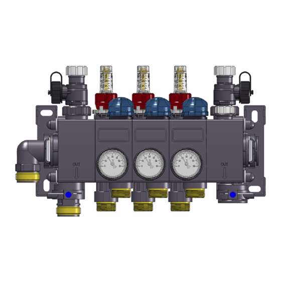
Transport und Lagerung Transport und Lagerung Das Produkt kann durch unsachgemäßen Transport und Lagerung beschä- digt werden. HINWEIS UNSACHGEMÄSSE HANDHABUNG • Stellen Sie sicher, dass während des Transports und der Lagerung des Pro- dukts die spezifizierten Umgebungsbedingungen eingehalten werden. • Benutzen Sie für den Transport die Originalverpackung. - Page 8 Produktbeschreibung Produktbeschreibung Übersicht Standardausführung Lieferumfang A. Einsteckwinkel (G1a) 1. Thermometer (Vorlauf) B. Wandhalter mit stufenlos einstell- 2. 4 x Dämmplatte barem Abstand 3. 2 x Absperrventil C. Füll-/Entleerhahn (KFE-Hahn) 4. Befestigungsset: D. Entlüftungsventil 4 x Unterlegscheibe - Optional: Schnellentlüfter 4 x Schraube 6 x 60 4 x Dübel 8 x 51...
- Page 9 Produktbeschreibung Abmessungen Heizkreise 2 Abstand A 1 304 354 404 454 504 554 604 654 704 754 804 Abstand A 2 340 390 440 490 540 590 640 690 740 790 840 Abstand B 260 310 360 410 460 510 560 610 660 710 760 Abbildung 1: Maße in mm ProCalida®...
- Page 10 Produktbeschreibung 86 bis 114 Abbildung 2: Maße in mm Technische Daten Parameter Wert Hauptanschluss G1 Innengewinde Heizkreisanschluss G¾ Eurokonus Betriebstemperatur Maximal 60 °C Betriebsdruck Maximal 6 bar Prüfdruck 10 bar bei 20 °C Lieferbare Größen 2 bis 12 Heizkreise ProCalida® CC 1...
- Page 11 Produktbeschreibung Diagramme Abbildung 3: Druckverlustkurven abhängig von Massenstrom und Öffnungswinkel bei Verteilern mit Durchflussmesser. Druckverlust am Rücklaufventil berücksichtigt. A. Druckverlust [bar] B. Massenstrom [kg/h] Abbildung 4: Diagramm Gesamtdruckverlust mit Durchflussmesser. ProCalida® CC 1...
-
Page 12: Montage
Montage Montage HINWEIS UNSACHGEMÄSSE HANDHABUNG Verschmutzte oder beschädigte O-Ringe können zu Undichtheit des Produkts führen. • Stellen Sie sicher, dass die O-Ringe bei der Montage sauber und unbeschä- digt sind. Nichtbeachtung dieser Anweisungen kann zu Sachschäden führen. Falls nicht anders angegeben, beziehen sich alle Angaben zur Montage auf folgende Einbauweise: •... - Page 13 Montage Produkt montieren Das Produkt muss links mit einem Wandhalter und rechts mit einem Wand- halter befestigt werden. Stellen Sie sicher, dass die beigelegten Dübel für die vorgesehene Wand geeignet sind. 1. Stecken Sie die Dämmplatten (A) auf den linken und den rechten Wandhalter.
- Page 14 Montage 3. Zeichnen Sie die Position der Bohrlöcher beider Wandhalter an. 4. Bohren Sie die angezeichneten Löcher (Bohrer Ø 8 mm). 5. Befestigen Sie das Produkt mit den beiliegenden Dübeln, Unterlegscheiben und Schrauben. ProCalida® CC 1...
- Page 15 Montage Absperrventil montieren HINWEIS UNSACHGEMÄSSE HANDHABUNG Verschmutzte oder beschädigte Dichtungen können zu Undichtheit des Pro- dukts führen. • Stellen Sie sicher, dass die Dichtungen bei der Montage sauber und unbe- schädigt sind. Nichtbeachtung dieser Anweisungen kann zu Sachschäden führen. 1. Schrauben Sie die Absperrventile (C) mit maximal 70 Nm am Einsteckwinkel (A) und...
- Page 16 Montage Anschlüsse umbauen (am Beispiel von links nach rechts) 1. Hebeln Sie die Klammern mit einem Schraubendreher (C) her- aus. 2. Ziehen Sie den Einsteckwinkel (A) und den Einsteckstutzen (B) aus dem linken Anschlussseg- ment. 3. Hebeln Sie die Klammern mit einem Schraubendreher heraus.
- Page 17 Montage 6. Stecken Sie den Einsteckwinkel (A) und den Einsteckstutzen (B) in das rechte Anschlusssegment. 7. Sichern Sie den Einsteckwinkel (A) und den Einsteckstutzen (B) mit den Klammern. 8. Verschließen Sie mit den Blindstopfen die nicht benö- tigten Anschlüsse. 9. Sichern Sie die Blindstop- fen mit den Klammern.
- Page 18 Montage 4. Tauschen Sie den Einsteckwinkel (A) und den Einsteckstutzen (B). 5. Stecken Sie den Einsteckwinkel (A) und den Einsteckstutzen (B) in das Anschlusssegment. 6. Sichern Sie den Einsteckwinkel (A) und den Einsteckstutzen (B) mit den Klammern. 7. Ziehen Sie das Thermome- ter ab und befestigen Sie es am Absperrventil des Vor- laufs.
- Page 19 Montage Heizkreise erweitern (optional) Bei Bedarf kann das Produkt auf bis zu 14 Heizkreise erweitert werden. SW 10 1. Entfernen Sie die Abdeckkappen (J). 2. Schrauben Sie die Muttern (I) (SW 10) ab und entfernen Sie die Unterlegscheiben (H). 3. Ziehen Sie den Wandhalter (G) ab. 4.
- Page 20 Montage Schnellentlüfter montieren (optional) 1. Schrauben Sie das Entlüftungsventil (A) lose. 2. Hebeln Sie das Entlüftungs- ventil mit dem beiliegendem Spezialwerkzeug (B) her- aus. 3. Schrauben Sie den Schnellentlüfter (C) fest. - Beachten Sie die Betriebsanleitung des Schnellentlüfters. Produkt nachrüsten WARNUNG HEISSE MEDIEN Medien in Heizungsanlagen stehen unter einem hohen Druck und können Tem-...
- Page 21 Inbetriebnahme Inbetriebnahme Voraussetzung für die Inbetriebnahme ist eine vollständige Installation aller Komponenten. Die Anlage muss während und nach dem Befüllen entlüftet werden. Anlage spülen und befüllen 1. Schließen Sie die Absperrventile (E). 2. Schließen Sie an beide Füll-/Entleerhähne (A) je einen Schlauch an. 3.
- Page 22 Inbetriebnahme Anlage entlüften 1. Schließen Sie den mitge- lieferten Schlauch am Entlüftungsventil (A) an. 2. Entlüften Sie die Anlage über das Entlüftungsventil (A). Druckprobe und Funktionsprüfung durchführen 1. Führen Sie eine Druckprobe mit 6 bar durch. - Der Anlagendruck muss mindestens zwei Stunden konstant bleiben (maximaler Druckabfall 0,2 bar).
- Page 23 Inbetriebnahme Vorlaufventile einstellen 1. Öffnen Sie das Vorlaufventil so weit, bis die errechnete Wassermenge (A) am Durch- flussmesser angezeigt wird. 2. Ziehen Sie den Einstellring zum Entriegeln nach oben. ProCalida® CC 1...
- Page 24 Inbetriebnahme 3. Drehen Sie den Einstellring bis zum Anschlag des Vorlaufventils. 4. Drücken Sie den Einstellring zum Verriegeln nach unten. ProCalida® CC 1...
-
Page 25: Wartung
2. Entsorgen Sie das Produkt. Rücksendung Vor einer Rücksendung Ihres Produkts müssen Sie sich mit uns in Verbin- dung setzen (service@afriso.de). Gewährleistung Informationen zur Gewährleistung finden Sie in unseren Allgemeinen Geschäftsbedingungen im Internet unter www.afriso.com oder in Ihrem Kauf- vertrag. ProCalida® CC 1... -
Page 26: Ersatzteile Und Zubehör
Ersatzteile und Zubehör Ersatzteile und Zubehör HINWEIS UNGEEIGNETE TEILE • Verwenden Sie nur Original Ersatz- und Zubehörteile des Herstellers. Nichtbeachtung dieser Anweisung kann zu Sachschäden führen. Produkt Artikelbezeichnung Art.-Nr. Abbildung Heizkreisverteiler ProCalida® CC 1 2-HK 81482 Heizkreisverteiler ProCalida® CC 1 3-HK 81483 Heizkreisverteiler ProCalida®... - Page 27 Operating instructions Heating circuit manifold ProCalida® Type: CC 1 Copyright 2023 AFRISO-EURO-INDEX GmbH. All rights reserved. Version: 09.2023.0 ID: 900.000.1090...
- Page 28 About these operating instructions About these operating instructions These operating instructions describe the heating circuit manifold ProCalida® CC 1 (also referred to as "product" in these operating instruc- tions). These operating instructions are part of the product. • You may only use the product if you have fully read and understood these operating instructions.
-
Page 29: Information On Safety
Information on safety Information on safety Safety messages and hazard categories These operating instructions contain safety messages to alert you to poten- tial hazards and risks. In addition to the instructions provided in these oper- ating instructions, you must comply with all directives, standards and safety regulations applicable at the installation site of the product. - Page 30 Information on safety Intended use This product may only be used for the distribution of media in surface heating systems and cooling systems in buildings. This product is suitable for opera- tion with the following media: • Heating water as per VDI 2035 •...
- Page 31 Information on safety Predictable incorrect application The product must never be used in the following cases and for the following purposes: • Distribution of drinking water Qualification of personnel Only appropriately trained persons who are familiar with and understand the contents of these operating instructions and all other pertinent product doc- umentation are authorized to work on and with this product.
-
Page 32: Transport And Storage
Transport and storage Transport and storage The product may be damaged as a result of improper transport or storage. NOTICE INCORRECT HANDLING • Verify compliance with the specified ambient conditions during transport or storage of the product. • Use the original packaging when transporting the product. •... -
Page 33: Product Description
Product description Product description Overview Standard version Scope of delivery A. Plug-in elbow (G1e) 1. Thermometer (flow) B. Wall bracket with fully adjustable 2. 4 x insulation plate distance 3. 2 x shut-off valve C. Filling/drain valve (KFE valve) 4. Fastening kit: D. - Page 34 Product description Dimensions Heating cir- cuits Distance A 1 304 354 404 454 504 554 604 654 704 754 804 Distance A 2 340 390 440 490 540 590 640 690 740 790 840 Distance B 260 310 360 410 460 510 560 610 660 710 760 Fig.
- Page 35 Product description 86 to 114 Fig. 2: Dimensions in mm Technical specifications Parameter Value Main connection G1 female thread Heating circuit connection G¾ eurocone Operating temperature 60 °C maximum Operating pressure 6 bar maximum Test pressure 10 bar at 20 °C Available sizes 2 to 12 heating circuits ProCalida®...
- Page 36 Product description Charts Fig. 3: Pressure loss curves depending on flow stream and opening angle of mani- folds with flow meter. Pressure loss at return valve considered. A. Pressure loss [bar] B. Flow stream [kg/h] Fig. 4: Chart total pressure loss with flow meter. ProCalida®...
- Page 37 Mounting Mounting NOTICE INCORRECT HANDLING Dirty or damaged O rings can cause leaks of the product. • Verify that the O rings are clean and free from damage during mounting. Failure to follow these instructions can result in equipment damage. Unless otherwise specified, all information on mounting relates to the follow- ing installation type: •...
- Page 38 Mounting Mounting the product The product must be fastened with a wall bracket on the left and a wall bracket on the right. Verify that the enclosed dowels are suitable for the intended wall. 1. Push the insulation plates (A) onto the left and the right wall bracket.
- Page 39 Mounting 3. Mark the position of the drill holes of both wall brackets. 4. Drill the marked holes (drill Ø 8 mm). 5. Mount the product using the enclosed dowels, washers and screws. ProCalida® CC 1...
- Page 40 Mounting Mounting the shut-off valve NOTICE INCORRECT HANDLING Dirty or damaged seals can cause leaks of the product. • Verify that the seals are clean and free from damage during mounting. Failure to follow these instructions can result in equipment damage. 1.
- Page 41 Mounting Inverting the connections (example from left to right) 1. Remove the clips with a screwdriver (C). 2. Remove the plug-in elbow (A) and the plug-in connection piece (B) from the left connection seg- ment. 3. Remove the clips with a screwdriver.
- Page 42 Mounting 6. Push the plug-in elbow (A) and the plug-in connection piece (B) into the right con- nection segment. 7. Secure the plug-in connec- tion piece (A) and the plug-in connection piece (B) with the clips. 8. Close the unused connec- tions with the blind plugs.
- Page 43 Mounting 4. Interchange the plug-in elbow (A) and the plug-in connection piece (B). 5. Plug the plug-in elbow (A) and the plug-in connection piece (B) into the connec- tion segment. 6. Secure the plug-in connec- tion piece (A) and the plug-in connection piece (B) with the clips.
- Page 44 Mounting Extending heating circuits (optional) If required, the product can be extended to up to 14 heating circuits. SW 10 1. Remove the cover caps (J). 2. Unscrew the nuts (I) (spanner size 10) and remove the washers (H). 3. Remove the wall bracket (G). 4.
- Page 45 Mounting Mounting a quick air vent (optional) 1. Loosen the vent valve (A). 2. Remove the vent valve with the enclosed special tool (B). 3. Screw in the quick air vent (C). - Observe the operating instructions for the quick air vent.
- Page 46 Commissioning Commissioning Prerequisite for commissioning is a complete installation of all components. The system must be vented during and after filling. Flushing and filling the system 1. Close the shut-off valves (E). 2. Connect a hose each to both filling/drain valves (A). 3.
- Page 47 Commissioning Venting the system 1. Connect the enclosed hose to the vent valve (A). 2. Vent the system via the vent valve (A). Performing the pressure test and the function test 1. Perform a pressure test with 6 bar. - The system pressure must remain constant for at least two hours (max- imum pressure drop 0.2 bar).
- Page 48 Commissioning Adjusting the flow valves 1. Open the flow valve until the cal- culated water volume (A) is indi- cated at the flow meter. 2. Pull the adjustment ring up to unlock. ProCalida® CC 1...
- Page 49 Commissioning 3. Turn the adjustment ring all the way to the mechanical stop of the flow valve. 4. Push the adjustment ring down to lock. ProCalida® CC 1...
-
Page 50: Maintenance
1. Dismount the product (see chapter "Mounting", reverse sequence of steps). 2. Dispose of the product. Returning the device Get in touch with us before returning your product (service@afriso.de). Warranty See our terms and conditions at www.afriso.com or your purchase contract for information on warranty. ProCalida® CC 1... -
Page 51: Spare Parts And Accessories
Spare parts and accessories Spare parts and accessories NOTICE UNSUITABLE PARTS • Only use genuine spare parts and accessories provided by the manufac- turer. Failure to follow these instructions can result in equipment damage. Product Product designation Part no. Figure Heating circuit manifold 81482 ProCalida®... - Page 52 Spare parts and accessories Spare parts and accessories Product designation Part no. Figure ProCalida® CC 1 extension kit 1 HK 81481 Pressure gauge RF50/10bar for ProCalida 81276 ProCalida® CC 1...
Need help?
Do you have a question about the ProCalida CC 1 and is the answer not in the manual?
Questions and answers