Advertisement
Quick Links
Advertisement

Related Manuals for KIP 700m


Summary of Contents for KIP 700m
- Page 1 Service Manual Version B.0a...
- Page 2 Chapter 1 Introduction Page 1. 1 Features 1- 2 1. 2 Specifications 1- 3 1. 2. 1 General 1- 3 1. 2. 2 Printer part 1- 4 1. 2. 3 Scanner part 1- 6 1. 3 Specifications for Originals 1- 7 1.
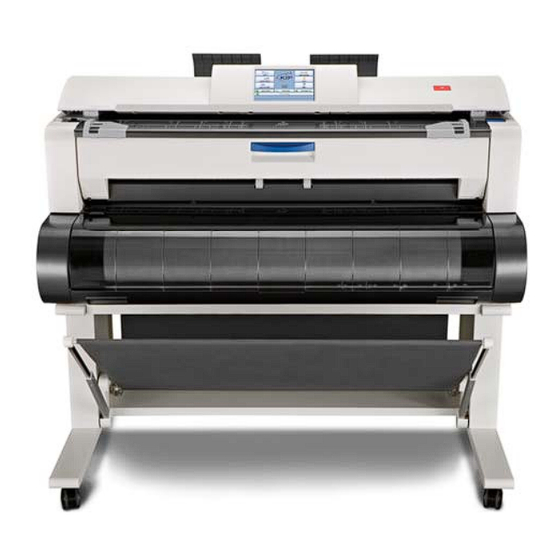
- Page 3 1. 1 Features (1) KIP 700m is a Multi-Function Printer for scan, copy and print large format documents. Some of these features may be optional. (2) Front loading - front delivery structure saves the installation space. (3) Various media source; roll media feeding (1 roll), cut sheet manual feeding, Paper Tray multiple cut sheet feeder (option).
- Page 4 1. 2 Specifications 1. 2. 1 General Subject Specification Model KIP 700m Configuration Console Power consumption 1500w (US model) (Maximum) 1600w (Europe/Asia model) (Including Scanner & Controller Unit) Power consumption 13w or less (US model) (Low power mode) 13.5w or less (Europe/Asia model)
- Page 5 1. 2. 2 Printer part Subject Specification Printing method LED Array Electro photography Photoreceptor Organic Photoconductive Drum Print speed 40mm per second (Inch) 1.7ppm/E 2.9ppm/D Landscape (Metric) 1.6ppm/A0 2.8ppm/A1 Landscape Print head LED Array Resolution of print head 600dpi x 600dpi Print width Maximum 914mm / “36”...
- Page 6 Subject Specification Media source 1 Roll Deck (3” / 2” core roll) Manual Feeder (single cut sheet) Paper Tray (multiple cut sheet, option) Media (Recommended Roll Media) - US model: Bond : 64g/m to 80g/m , US Bond (20# Bond) Vellum : US Vellum (20# Vellum) Film...
- Page 7 1. 2. 3 Scanner part Subject Specification Scanning method Contact Image Sensor (CIS) (5 pieces of A4 sized CIS) Light source LED (R/G/B) Setting of original Face up Starting point of scan Center Scan width Max: 914.4mm / 36” Min : 210mm Scan length Max:...
- Page 8 1. 3 Specifications for Originals 1. 3. 1 Original Standards (1) The width of original must range from 8.5” to 36” (210mm to 914.4mm). (2) The length of original must range 8.5” (210mm) to 25,000mm (3) The thickness of original must range from 0.05mm to 0.65mm. (Old Scanner) (4) The thickness of original must range from 0.05mm to 0.25mm.
- Page 9 1. 4. 1 Front Name Function Main Switch You can turn on/off the KIP 700m. Original Guides Feed the original under the Scanner Unit along the Original Guides. User Interface This is a Touch Screen, and many kinds of user operation are available.
- Page 10 Open here to access toner supply system. Original Guide These trays catch the original ejected from the Scanner Unit. LAN Port Connect the LAN Cable to connect the KIP 700m to the network. (Do not connect a telephone line) USB Port Service Use, 5VDC max. Breaker It is possible to shut off supplying the AC power.
- Page 11 1. 5 Specifications for Scan Original A scan original must satisfy the following specifications. Thickness 0.05mm to 1.60mm *1 *2 Width 210mm to 914.4mm Length 210mm to 6,000mm *1. If an original is thicker than 0.65mm, its image quality is not guaranteed even it is transported. (Old Scanner) *2.
- Page 12 Not square Wet image Made of metal or fabric Metal Fabric Patched Clipped or stapled Clipped Stapled 1-11 K117sm1e1...
- Page 13 The following kinds of originals can be read with using a carrier sheet. Image quality or the reliability of paper feeding for them is not guaranteed. Rough surface Rough surface (Carbon paper for example) Punched 1-12 K117sm1e1...
- Page 14 1. 6 Specifications for Printing Media 1. 6. 1 Papers not available to use Do not use the following kinds of printing paper because you may damage the print engine! Excessively curled (a diameter of 50 mm or less) Folded Creased Torn Punched...
- Page 15 Paper that has already been used for printing Extremely sticky Extremely thin and soft Extremely slippery OHP Film CAUTION Do not use the paper with staple, or do not use such conductive paper as aluminium foil and carbon paper. Such paper may become cause for the fire. NOTE (1) Print image may become light if printed on a paper of rough surface.
- Page 16 1. 6. 3 Treatment against environmental condition Humidity(%) Possible problem Necessary treatment “Void of image”, “crease of paper” and 1. Install an humidifier in the room, and other problems occurs when you print humidify the room air. with plain paper and tracing paper. 2.
- Page 17 Chapter 2 Installation The machine had passed our strict inspection after careful adjustment in the factory, and then it was packaged and shipped. Installation is an important work to make the machine work at customer’s site as same as it has passed our strict inspection before shipment. A service engineer has to understand machine’s function very well.
- Page 18 2. 1 Unpack The next page shows the unpacking procedure. This is printed on the outside of the product carton. K117sm2e1...
- Page 19 MULTI-FUNCTION PRINTER NOTE / 700m (1) When this printer is installed in winter, if a printer that has been kept in (2) Handle with great care when you unpack or install Unpacking Procedure a cold warehouse is moved to a warm room and is unpacked, it may the printer because its net weight is about 180Kg.
- Page 20 Keep ample space around the equipment to ensure comfortable operation. The floor must be level and the strength must be ample to sustain the weight of the equipment. 20cm/8” or larger with no option (Rear) 10cm/4” or larger 10cm/4” or larger KIP 700m (Front) 20cm/8” or larger K117sm2e3...
- Page 21 Wrench User’s Manual CD Information Sheet Hardware Setup User’s Manual *Europe model only Procedure Leaflet (German) (This leaflet) *Europe model only NOTE The Wrench is designed for only installing / uninstalling the KIP 700m. Use only for intended purpose. K117sm2e3...
- Page 22 2. 4 Stand Setup 1. Pass Rear Stay (1) through the loop at the 2. Fix Swing Arm Assy (3) to the bottom plate of Stand with end of the cloth of Sheet Assy (2). Thumb Screw (4). 3. Put the end of Rear Stay (1) on the Bracket (5). Make sure to face the holes on the L-shape toward the floor.
- Page 23 2. 5 Scanner Part 1. Press the levers (1) up to open the Scanner Unit. 2. Remove the protection mat (2) and the Protection Sheet (3). 3. Gently press both sides of the Scanner Unit down to firmly close it. 2.
- Page 24 2. 7 Inner Feeder Unit Setup 1. Press down the blue levers (1) on both sides to unlock and open the Upper Unit. 2. Remove the shock absorber (2), (3) on both sides. 3. Remove the tape (4) to release the drive belt (5). 4.
- Page 25 5. Open the Guide Plate (8), and remove the shock absorbers (9) and tags (10) on both sides. 6. Close the Guide Plate (8). Return the Transfer / Separation Corona (7) in position. 2. 8 LED Head Assy Setup 1. Remove 2 tapes. (1) 2.
- Page 26 NEVER 3. Pinch and hold the dotted area in the picture. touch the LED Array (3) and the LED Head Bracket (4). Slightly lift up the LED Head Assy to remove Fixing Plate (5). The pictures on this step show the right side. Please do the same way for the left side too. Do not touch 4.
- Page 27 2. 9 Developer Unit Setup 1. Remove 2 thumb screws (1) to remove the red brackets (2) on each side. The brackets (2) are no longer required. 2. Remove the stickers (3) on the “flap areas” on the top of the black sheet (4).
- Page 28 2. 10 Process Unit Setup NOTE Direct this face up. 1. Please handle the Process Unit with great care as it is equipped with the Drum. Rough handling may damage the Drum. 2. Please confirm the table is flat when you put the Process Unit on it.
- Page 29 4. With fitting the square holes (3) to the pins (4), install the Process Unit to the Upper Unit of printer. Process Unit 5. Secure the Process Unit by tightening 4 thumb screws (5). 7. Finish the setup of Process Unit by closing the 6.
- Page 30 2. 11 Installing Accessory Remove 2 tapes (1). Fit 2 Guides (2) into the slots on the rear cover of printer. 2. 12 Supplying Initial Toner 1. Open the Toner Hatch (1) on the rear cover of the printer. (Not necessary to remove the Guide) from right 2.
- Page 31 3. Put the dent area (3) under the holder (4) to firmly seat the bottom plate of the Toner Bottle to the toner supply position. from front from front from right 4. With pressing down the Toner Bottle, slide from right the green lever (5) to the arrow direction until it stops.
- Page 32 6. Connect the Power Cable and turn on the printer. For power source requirements, see page 1. The UI screen shows “Setup Wizard”. It will prompt you to enter several settings. Follow the wizard for the rest of the setup. 2.
- Page 33 3. Service Configuration screen will appear. Press the arrow keys to move to page 5/7. On 5/7 page, press [Launch]. Use the arrow keys to open [5/7 IPS Setup]. 4. A confirmation dialog appears. Press [Yes]. Press [Login] to log in Service Mode. 5.
- Page 34 6. Entry Serial Number screen will appear. Input the serial number and press [Enter]. 7. Install a Removable storage device to the printer. Locate “Removable Disk” and press [Save]. The current setting parameters are saved as *.RAM and *.txt in a folder (automatically created) at this time. If you do not have one, please locate a folder in the HDD of the controller.
- Page 35 9. When RAM file is created in a USB storage, follow the instruction in another dialog. Press [Yes] and [OK] before you remove it. 10. Press [Back], [Logout] then [Close] to cancel Service Mode. 11. UI screen will display Home screen in a short time. 2-18 K117sm2e3...
- Page 36 Following step is for new scanner The later pages show the Stitching Adjustment for the reading sensors on the scanner unit to enhance the scanning quality. (recommended) 2-19 K117sm2e3...
- Page 37 2. 14 Stitching Adjustment (for New Scanner) 2. 14. 1 Launching K129 Diag 1. Press [? HELP] on the Home screen. 2. Press [Service]. Input “8495107” and press [Enter]. 3. Service Configuration screen will appear. On “Setup Menu 1”, press [OK]. 2-20 K117sm2e3...
- Page 38 4. Press [Reset]. 5. Minimize the “IPS Unattend” window. 6. Open “Diagnostics” folder (gear icon) in the lower right of the screen. 2-21 K117sm2e3...
- Page 39 7. Double click [Hardware Utilities] and [K129 CIS Scanner – Utility Ver.X.X.X.X.XX]. 8. Run “K129 Diag”. Reference Other ways to run the "K129 Diag" are described on the next page. 2-22 K117sm2e3...
- Page 40 Reference 1. Contact your KIP partner for K129Diag.exe and save it to any available storage on your USB storage. Connect removable storage to UI monitor’s connector. USB storage 2. Select “Removable Disk”, and then run “K129 Diag.exe”. 2-23 K117sm2e3...
- Page 41 2. 14. 2 Stitching Adjustment NOTE BUD No.15 (stitch setting 1) should be temporarily set to OFF “0” during Stitching Adjustment. 1. Run K129 Diag. Click [BackupData] to recall “Backup Data” sub window. 2. Click [Receive] 2-24 K117sm2e3...
- Page 42 3. The current parameters are retrieved and displayed in the list. 4. Double click on the row No.15 “Stitch Setting 1”. 2-25 K117sm2e3...
- Page 43 5. In “FormInput” screen, Click [Virtual Keyboard] to display the screen keypad. 6. Type “0” with keypad, and then click [OK] on the bottom. 7. Click [OK] on the bottom. 2-26 K117sm2e3...
- Page 44 8. The setting change you have made is reflected to the list. It will turn blue. Click [Send] on the bottom. The setting change turns black. Now it is sent to the Main Board. 2-27 K117sm2e3...
- Page 45 9. To close “BackupData” sub window, click the X button at the upper right corner. 10. Clean Glass DCMNT with a soft cloth. 11. Set the Shading Sheet to the scanner noting the arrow direction. NOTE No skew insertion. Doing so may cause an incorrect calibration. 12.
- Page 46 13. Select “Stitching Adjustment” in the upper drop-down menu. 14. Click [Start] beside the upper drop-down menu. NOTE If an error message occurs; 1. Correctly set the Shading Sheet to the scanner. 2. Check for dirt on the Glass DCMNT and the Shading Sheet. 2-29 K117sm2e3...
- Page 47 15. When the scanning is finished, two sub windows “Stitch Simulate” and “Stitch Adjust” appear. Enlarge “StitchAdjust” window. Enlarge “Stitch Adjust” window. 2-30 K117sm2e3...
- Page 48 16. There are 4 target signs at every border between the CIS. CIS 1 CIS 2 CIS 3 CIS 4 CIS 5 In “Stitch Adjustment” window, Select [Jump] menu, and then click [CIS1 to CIS2]. The display area will jump to the corresponding area on the scanned image.
- Page 49 17. Confirm the Stitching Adjustment results. no misalignment vertical misalignment horizontal misalignment this may include vertical & horizontal misalignment at a time 18. Select [Jump] menu, and then click the other CIS borders to confirm the results. If all of the 4 targets have no misalignment, go to step 25. If any of the targets has an misalignment, go to step 19 and after for manual correction.
- Page 50 19. First, correct vertical misalignment as follows. 19-1. In “StitchSimulate” window, click the buttons (see below in blue frame) to change the setting value for “vertical” (see below in red frame), in order to move the image block vertically. vertical misalignment this may include vertical &...
- Page 51 20. Second, correct horizontal misalignment as follows. 20-1. In “StitchSimulate” window, click the buttons (see below in blue frame) to increase / decrease the setting value for “horizontal” (see below in red frame). This moves the image block horizontally. horizontal misalignment Do the same way for all the 4 targets at the CIS borders if needed.
- Page 52 21. The manual correction is reflected to “StitchAdjust” window directly. Reconfirm the manual correction result on the 4 targets. If there is still misalignment, go back to step 19 and 20 to remove it. NOTE Be sure to reconfirm the manual correction result. no misalignment 22.
- Page 53 23. In “StitchAdjust” window, select [Control] menu, and then click [Confirm-Scan] to make another scan. 24. The rescan result can be checked in “StitchAdjust” window. 25. Click the X button at the top right corner to close “StitchAdjust” and “StitchSimulate” sub windows. 26.
- Page 54 28. The current parameters are retrieved and displayed in the list. 29. Double click on the row No.15 “Stitch Setting 1”. 30. In “FormInput” screen, Click [Virtual Keyboard] to display the screen keypad. 2-37 K117sm2e3...
- Page 55 31. Type “4” with keypad, and then click [OK] on the bottom. 32. Click [OK] on the bottom. 2-38 K117sm2e3...
- Page 56 33. The setting change you have made is reflected to the list. It will turn blue. Click [Send] on the bottom. The setting change turns black. Now it is sent to the Main Board. 2-39 K117sm2e3...
- Page 57 2. 14. 3 Creating Backup Data NOTE To easily recover the scanner in case of lost / crash of the BUDs, follow the instruction below to create a backup. If you have quitted Backup Data window in the previous section, click [Backup Data] in the home screen, click [Receive] 2-40 K117sm2e3...
- Page 58 1. Select “File” menu, and click “Save As.” 2. Specify the location to create a backup (csv), and then click [Save]. 2-41 K117sm2e3...
- Page 59 3. Click the X button to quit “BackupData” sub window and K129 Diag. 4. Run “Restart GUI” and the user’s GUI reappears. 5. Turn off the printer, wait for some seconds, and turn it on again. (completed) 2-42 K117sm2e3...
- Page 60 Chapter 3 Print / Scan Process Page 3. 1 Print Process 3- 2 3. 1. 1 Characteristic of toner 3- 2 3. 1. 2 Each step of the print process 3- 3 3. 1. 2. 1 Erasing (Removal of negative electric charges) 3- 5 3.
- Page 61 3. 1. 1 Characteristic of toner The toner used for KIP 700m has a characteristic to be charged “negative”, which tends to be attracted to a more “positive” object. Suppose that there are objects A and B, and the situation is as follows.
- Page 62 3. 1. 2 Each step of print process One cycle of print consists of the following 8 processes. 1. Erasing (Removal of negative electric charges) 2. Charge of Drum 3. Exposure 4. Development 5. Transfer 6. Separation 7. Drum Cleaning (Removal of remained toner) 8.
- Page 63 When the printer is going to stop after printing, or when the used Roll Deck is changed with other one, the KIP 700m will take the “Toner Collection Process” to remove the remained toner and place back into the Developer Unit.
- Page 64 3. 1. 2. 1 Erasing (Removal of negative electric charges) As the first step of print cycle, it is necessary to remove the negative electric charges from the Drum, which have remained there after the former print cycle. The Drum has a characteristic to lose the negative electric charges if it is exposed to the light. So the Drum is rotated and evenly exposed to the light from the Eraser Lamp.
- Page 65 3. 1. 2 .2 Charge of Drum The Image Corona discharges negative electric charges which are given to the Drum. The surface of Drum becomes about -630V evenly as a result, which corresponds to the white area of the printed image pattern. The Grid Plate is also connected to the High Voltage Power Supply individually.
- Page 66 3. 1. 2. 3 Exposure According to the printed image pattern, the LED Head throws the light (740nm) onto some part of Drum which corresponds to the black area of printed image pattern. As the Drum has a characteristic to lose the negative electric charges if it is exposed to the light, this part of Drum surface loses the charges and its potential becomes about -20V.
- Page 67 (9 micrometers) is much smaller than that (42 micrometers) of 1 pixel of LED. The electric charges on the Drum are removed as needed. (2) The KIP 700m’s LED Head Unit consists of 3 blocks. Block A / C...
- Page 68 3. 1. 2. 4 Development The Developer Roller, which is evenly covered with the toner, is contacted to the Drum because the Developer Unit is pressed to the Drum. (The width of contact point is about 5mm.) The Developer Roller is supplied with -230V during the print cycle. And both -630V area and -20V area exist on the Drum because the Electrostatic Latent Image has been formed in the former Exposure process.
- Page 69 Even if some toner has not been removed by the Cleaning Roller but remained on the -630V area of Drum (It corresponds to the white area of the print) in the later [3.1.2.7 Drum Cleaning], this toner is removed at the time of Development because it moves to the Developer Roller of which potential (-230V) is higher than that of Drum (-630V).
- Page 70 3. 1. 2. 5 Transfer The printing paper is charged positively as the Transfer Corona discharges positive electric charges from under the paper. The toner existing on the -20V area on the Drum will move to the printing paper because the potential of the paper comes to be higher than the Drum by the Transfer Process.
- Page 71 3. 1. 2. 6 Separation The printing paper is attracted to the Drum after the Transfer because the potential of paper is positive and that of Drum is negative. It is necessary for avoiding the jam to separate the paper from the Drum by removing the static force between them.
- Page 72 3. 1. 2. 7 Drum Cleaning (Removal of remained toner) Some amount of toner that has not been transferred onto the printing paper is remaining on the Drum. This remained toner will be removed by the Cleaning Roller. The Cleaning Roller is supplied with +450V (+/-5V), and there are some negative electric charges on the Drum at this time.
- Page 73 3. 1. 2. 8 Fusing After Transfer / Separation Processes, the printing paper is transported to the Fuser Unit. The Fuser Unit mainly consists of the Fuser Roller and the Pressure Roller. The Fuser Roller is very hot, and the Pressure Roller is strongly pressed to the Fuser Roller by the spring.
- Page 74 3. 1. 3 Controlling the movement of toner in the Developer Unit There are 3 kinds of rollers called “Developer Roller”, “Regulation Roller” and “Toner Supply Roller” in the Developer Unit. Each roller is supplied with its own voltage. In the following list, the voltage of the Developer Roller (-230V) is measured against the ground. The other voltages mean the difference against the voltage of Developer Roller Bias.
- Page 75 Taking advantage of the difference of potentials among these rollers, the movement of toner is controlled in the Developer Unit as follows. 1. The Toner Supply Roller carries the toner toward the Developer Roller. 2. When the toner reaches the contact point of these rollers, therefore, it moves onto the Developer Roller.
- Page 76 5. The voltage of both sides of Regulation Roller is 0V as these parts are connected to the ground. It is higher than that of Developer Roller (-230V). When the toner reaches the contact point of these rollers, therefore, it moves onto the Regulation Roller.
- Page 77 3. 1. 4 Toner Collection Process As explained in [3.1.2.7 Drum Cleaning], the Cleaning Roller is supplied with +450V to remove the remained toner from the Drum during the print cycle. This toner gathered by the Cleaning Roller is returned to the Developer Unit in the following 3 cases.
- Page 78 3. The voltage supplied to the Developer Roller is also changed to +350V (+/-5V) in the Toner Collection Process. As the potential of Developer Roller becomes higher than that of Drum, toner on the Drum moves onto the Developer Roller. Then the toner is carried into the Developer Unit by both the Developer Roller and the Toner Supply Roller.
- Page 79 Reference Voltages supplied to Regulation Roller and Toner Supply Roller are changed also as follows. Name of roller Supplied voltage Developer Roller +350V +/-5V against the ground Regulation Roller -80V +/-5V against the Developer Roller Bias (Center) Regulation Roller 0V (Ground) (Both sides) Toner Supply Roller Same voltage with the Developer Roller Bias...
- Page 80 3. 1. 5 Density Compensation Process On rare occasion, loss of image density may occur under a special usage. KIP 700m has the ability to reduce such loss of image density and this enables to maintain a satisfactory image quality regardless of the machine usage.
- Page 81 Then it outputs the image data to the IPS through the USB 2.0. 4. The IPS output the image data to the printer part of KIP 700m through the Interface 8 in case of “copy”, or it outputs to the Network PC through the LAN cable in case of “scan to file”.
- Page 82 It outputs the image data to the IPS or PC through the USB 2.0. 4. IPS outputs the image data to the KIP printer through the Interface 8 on copy, or it outputs to the Network PC through the LAN cable on Scan to File.
- Page 83 Positioning process of Image Block The scanner part of KIP 700m reads the image of original with 5 - CIS (Contact Image Sensor). As these CIS are arranged in 2 rows, there occurs a vertical gap of image among the image blocks.
- Page 84 The Main Board removes the vertical gap among the Image Block according to the positioning setting (Y offset) specified through KIP Scanner Utility. The image data before the positioning process The image data after the positioning process (Y offset) 3-25...
- Page 85 Also the Main Board removes the duplication of image pixels among the Image Blocks according to the positioning setting (X overlap) specified through KIP Scanner Utility. The image data after the positioning process (Y offset) The image data after the positioning process (X overlap)
- Page 86 Chapter 4 Electrical Page 4. 1 General information 4- 1 4. 2 Electrical Component Location 4- 2 4. 2. 1 Right 4- 2 4. 2. 2 Left 4- 3 4. 2. 3 Rear 4- 4 4. 2. 4 Front 4- 5 4.
- Page 87 4. 1 General Information This machine is mainly controlled by a microcomputer, which is located on DC Controller. This microcomputer reads input signals from sensors, and outputs the operation signals to motors, SSRs, solenoid, clutches and blowers on programmed timing. Sensor Driver DC Load...
- Page 88 4. 2 Electrical Component Location 4. 2. 1 Right Item Symbol Signal name Name Type Function Switch AJ8R2004BBCF Switches ON/OFF the machine (Power Switch) Switch FA1L-CA22 Shuts off the AC power to the (Upper Unit Switch) DCP1 when the Upper Unit is open Noise Filter Removes the noise from the AC line...
- Page 89 4. 2. 2 Left Item Symbol Signal name Name Type Function FEED_BL ASFN60372 Assists to transport media (EXT_FAN) (Feed Blower) HV_IM HV Power Supply EUK1MGA60HA Outputs the high voltage to each of HV_TR the following components. HV_AC HVP4 (1) Image Corona (HV1) (2) Transfer Corona (HV2) OUTPUT2 BIAS_TRG...
- Page 90 4. 2. 3 Rear Item Symbol Signal name Name Type Function Line Filter RG-208F2 Removes the noise from the AC line 230V model only MAIN_TRG DC Motor DRG-6236-226 Drives the Drum, Developer Unit, (Main Motor) Fuser Unit and media feeding section ASFN90372 Cools the IPS and other...
- Page 91 4. 2. 4 Front Item Symbol Signal name Name Type Function Touch Touch Panel LCD Unit SLP0832-ETT- Touch Screen User Interface Screen (UI) DOOR_OPN Switch (Roll Deck AM51612C53 Detects Roll Deck Cover open Cover open) HAND_DOOR Switch (Manual Feed CS1A-B2CA Detects Manual Feeder Table Table open) open...
- Page 92 4. 2. 5 Process Frame / LED Head Item Symbol Signal name Name Type Function LED HEAD LED HEAD UNIT 53TRC Creates latent Images on Drum PW6693 HV-ZD Assy PW6693 - Keeps the Grid Voltage constant - Controls the surface potential of Drum PW11755 PW11755 Assy...
- Page 93 4. 2. 6 Main Frame Item Symbol Signal name Name Type Function DENS_S Sensor GP2Y40010K0 Detects the toner density on the (Toner Density Sensor) drum surface Outputs analog voltage to PW11720 Item Symbol Signal name Name Type Function BL1 / BL2 HEAT_BL Blower D12F-24BL 05...
- Page 94 4. 2. 7 Sensor on Media Path Item Symbol Signal name Name Type Function R1_SET_S Sensor PS119ED1 Detects whether the leading (Roll Set Sensor) edge is at set position RENC_S Sensor LG248NL1 Detects the distance of the roll (Feed Encoder) media feeding R_EDGE Sensor...
- Page 95 4. 2. 8 Cutter Unit Item Symbol Signal name Name Type Function MCUTL Motor Slides the cutter blade MCUTR (Cutter Motor) MSCUTL Switch (Cutter Home Detects whether the cutter blade MSCUTR Position Sensor) exists at the home position K117sm4e2...
- Page 96 4. 2. 9 Developer Unit Item Symbol Signal name Name Type Function TLS1 TONER_S Sensor TSP15DA10C- Detects whether the toner exists (Toner Sensor) in the Developer Unit TONER_M DC Motor DMA-3150A Drives the Toner Hopper to (Toner Supply Motor) supply the toner to the Developer Unit 4-10 K117sm4e2...
- Page 97 4. 2. 10 Fuser Unit Item Symbol Signal name Name Type Function Thermostat CH-152-35- Prevents over-heat Thermistor 1 FS-K0120 Detects the temperature on the central area of Fuser Roller Thermistor 2 FS-K0121 Detects the temperature on the Fuser Roller on the left HEAT_EXIT Sensor LG248NL1...
- Page 98 4. 2. 11 Scanner Unit (Old Scanner) Item Symbol Signal name Name Type Function Main Board (117) Makes image processes to the (data controller) digital data sent from SVC CIS BD And then it sends the processed image data to the controller CIS Board (117) Converts the analog data read by (CIS controller)
- Page 99 Item Symbol Signal name Name Type Function Sensor PS117ED1 - Detects the insertion of original (Original Set Sensor) - Detects original widths A4 (Size Sensor A4) (Portrait), 8.5”, 9” Sensor PS117ED1 Detects original widths A4 (Size Sensor A3) (Landscape), A3, 11”, 12” Sensor PS117ED1 Detects original widths A2, 17”, 18”...
- Page 100 D CON PW12920-02 Makes image processes to the (Data Controller PCB) digital data sent from CIS, and then sends the processed image data to KIP Printer. Converts the analog data read by the CIS to the digital data S_MS1 Switch CS1A-B2CA...
- Page 101 Item Symbol Signal name Name Type Function CIS Sensor FL06G-W07 Reads the image of original, and then send the analog data to D CON (Data Controller PCB). S_PH1 Sensor PS122GD4-A Detects the original to be inserted. Detects original width A4 (Portrait) S_PH2 Sensor PS122GD4-A...
- Page 102 Item Symbol Signal name Name Type Function Motor 103H7123-5746 Transports the original. S_PH9 Sensor LG248BL1 Detects rotations of FEED ROLLER 4-16 K117sm4e2...
- Page 103 4. 3 Check & Adjustment of Analog Output from HV Power Supply 4. 3. 1 Situations necessary to check the analog output It is necessary to check the analog output from High Voltage Power Supply after replacing the following parts. PW11720 PCB (DC Controller) HV Power Supply PCB (EUK1MGA60HA) Please check the analog output for each of the following part, and please adjust if it is out of the...
- Page 104 4. 3. 2 Analog Voltage to Image Corona The standard value of the voltage outputted from the HV Power Supply PCB to the Image Corona 1.30 +/-0.05V. Check and adjust the output current in the following way. 1. Connect the “+” cable of the multi-meter to the “CP11” pin on the HV Power Supply PCB (EUK1MGA60HA).
- Page 105 3. Adjust the output voltage if it does not satisfy 1.30 +/-0.05V. To adjust it, rotate the VR101 with a screwdriver. VR101 multimeter (DC) 4-19 K117sm4e3...
- Page 106 4. 3. 3 Analog Voltage to Transfer Corona The standard value of the voltage outputted from the HV Power Supply PCB to the Transfer Corona is specified as follows. Plain paper 1.00 +/-0.05V Tracing paper 1.00 +/-0.05V Film 1.00 +/-0.05V Check and adjust the output current in the following way.
- Page 107 2. Select the Test Print Mode, and make a test print using each type of paper (plain paper, tracing paper & Film) making reference to [8. 9 Test Print Mode]. As the high voltage is supplied to the Transfer Corona during the Test Print, check the voltage with the multi-meter.
- Page 108 4. 3. 4 AC Component to Separation Corona The standard value of the AC Component outputted from the HV Power Supply PCB to the 5.00 +/-0.05V. Separation Corona is Check and adjust the AC Component in the following way. 1. Connect the “+” cable of the multi-meter to the “CP31” pin on the HV Power Supply PCB (EUK1MGA60HA).
- Page 109 3. Adjust the AC Component if it does not satisfy 5.00 +/-0.05V. To adjust it, rotate the VR302 with a screwdriver. VR302 multimeter (DC) 4-23 K117sm4e3...
- Page 110 4. 3. 5 DC Component to Separation Corona The standard value of the DC Component outputted from the HV Power Supply PCB to the -250 +/-5V. Separation Corona is Check and adjust the DC Component in the following way. 1. Connect the “+” cable of the multi-meter to the “CP33” pin on the HV Power Supply PCB (EUK1MGA60HA).
- Page 111 3. Adjust the DC Component if it does not satisfy -250 +/-5V. To adjust it, rotate the VR303 with a screwdriver. VR303 ground multimeter (DC) 4-25 K117sm4e3...
- Page 112 4. 3. 6 Negative Developer Bias to Developer Roller The Negative Developer Bias means the voltage supplied to the Developer Roller during the Print Cycle. The standard value of the Negative Developer Bias is as follows for each type of paper. Plain paper -230 +/-5V against the ground Tracing paper...
- Page 113 2. Make a Test Print making reference to [8. 9 Test Print Mode]. As the Negative Developer Bias is supplied to the Developer Roller during the Test Print, check the voltage with the multi-meter. The standard value of the Negative Developer Bias for each type of media is: Plain paper -230 +/-5V against the ground Tracing paper...
- Page 114 4. 3. 7 Positive Developer Bias to Developer Roller The Positive Developer Bias means the voltage supplied to the Developer Roller during the Cleaning Cycle. 0.350 +/-0.005V against the CP42. The standard value of the Positive Developer Bias is Check and adjust the Negative Developer Bias in the following way. 1.
- Page 115 2. Make a Test Print making reference to [8. 9 Test Print Mode]. The Positive Developer Bias is supplied to the Developer Roller for some seconds after the printed paper has been ejected. Check the voltage with the multi-meter during that period. The standard value of the Positive Developer Bias is 0.350 +/-0.005V against the CP42.
- Page 116 4. 3. 8 Bias gap between Developer Roller and Regulation Roller The standard value of the Bias gap between Developer Roller and Regulation Roller is +/-5V. Check and adjust it in the following way. 1. Connect the “+” cable of the multi-meter to the “OUTPUT3” pin on the HV Power Supply PCB (EUK1MGA60HA).
- Page 117 3. If the value (voltage) is “120 +/-5V” or “160 +/- 5V”, Regulation Bias may be automatically adjusted by Density Compensation Process. “0006 Dev. Clear” Enter Special Operation Mode and then “ 2” 000000 The voltage “120V +/- 5V” is correct when the above 7-digit value shows “...
- Page 118 4. 3. 9 Positive Cleaning Roller Bias (Print Cycle) The Positive Cleaning Roller Bias means the voltage supplied to the Cleaning Roller during the Print Process. +450 +/-5V. The standard value of the Positive Cleaning Roller Bias is Check and adjust it in the following way. 1.
- Page 119 3. Adjust the Positive Cleaning Roller Bias if it does not satisfy +450 +/-5V. To adjust it, rotate the VR001 with a screwdriver. VR001 ground multimeter (DC) 4-33 K117sm4e3...
- Page 120 4. 3.10 Negative Cleaning Roller Bias (Toner Collection Process) The Negative Cleaning Roller Bias means the voltage supplied to the Cleaning Roller during the Toner Collection Process, which is done after the completion of Print Process. The standard value of the Negative Cleaning Roller Bias is -550 +/-5V.
- Page 121 3. Adjust the Negative Cleaning Roller Bias if it does not satisfy -550 +/-5V. To adjust it, rotate the VR002 with a screwdriver. VR002 ground multimeter (DC) 4-35 K117sm4e3...
- Page 122 Chapter 5 Mechanical Page 5. 1 Periodic Replacement 5- 1 5. 1. 1 Image Corona Unit 5- 1 5. 1. 2 Transfer / Separation Corona Unit 5- 6 5. 1. 3 Filters 5- 8 1476 5. 1. 4 Developer Unit 5-12 3424 5.
- Page 123 5. 1 Recommended Periodic Replacement This section describes the procedure of replacing some units that are recommended replacement for preventive maintenance. There are “light blue” stickers that show the “access point” for Periodic Replacement. For detailed information of the Service Kit contents, see Chapter 6. 5.
- Page 124 3. Loosen 4 thumb screws (4) to release the Process Unit (5). 4. Hold the handgrip (6) on both sides. Pull the Process Unit (5) to the arrow direction to remove it from the machine. NOTE THIS SIDE UP (1) Gently place the Process Unit (5) on a flat surface in the correct direction.
- Page 125 5. Pick the plastic area (8) on both sides. Release the pins (10) from the hook. Pull and remove the Image Corona Unit (9) from the Process Unit. 6. Install both the pins (10) to the hooks to seat the new Image Corona Unit in position.
- Page 126 7. Hold the handgrip (6) on both sides. Slightly tilt the Process Unit downward. Put the square holes (11) onto the tapered edges of the positioning pins (12). Before inserting completely, pivot the unit upward to face each other. Finally push the unit into the machine 8.
- Page 127 9. Return the belt (2) to the pulley (3). 10. Put your hands on the rear rim of the scanner unit just as you hold the Upper Unit. Push the entire unit down to the arrow direction. Hold here Hold here K117sm5e2...
- Page 128 5. 1. 2 Transfer / Separation Corona Unit 1. Press the blue lever (1) on both sides to open the Upper Unit. 2. Pick the plastic area (2) on both sides. Pull and remove the Transfer / Separation Corona Unit (3) from the machine. 3.
- Page 129 4. Put your hands on the rear rim of the scanner unit just as you hold the Upper Unit. Push the entire unit down to the arrow direction. Hold here Hold here K117sm5e2...
- Page 130 5. 1. 3 Filters 1. Remove 3 Bind Head Screws (M4x6) (1) on each side. 2. Press the blue lever (2) on both sides to open the Upper Unit. 3. Slightly lift Side Cover R (3) / Side Cover L (4) up to the arrow direction to remove then from the machine.
- Page 131 4. Replace Filter A (5) in Side Cover L (4) with a new one. 5. Replace Filter B (6) in the duct of the machine with a new one. 6. Replace Filter C (7) in the duct of the machine with a new one. K117sm5e2...
- Page 132 7. Make sure that the Upper Unit is open. Return Side Cover R (3) and Side Cover L (4) to the machine. Note that the hook part (8) should be seated in the square hole (9) of the machine. 8. Reinstall 4 of 6 screws (1) to loosely fix Side Cover R (3) and Side Cover L (4). NOTE Do not tighten the 4 screws (1) completely at this time.
- Page 133 9. Put your hands on the rear rim of the scanner unit just as you hold the Upper Unit. Push the entire unit down to the arrow direction. Hold here Hold here NOTE The small top tab parts (10) should fit inside of Side Cover R (3) and Side Cover L (4). 10.
- Page 134 5. 1. 4 Developer Unit Reference You can check what to do in step by step with using “Developer Replacement Wizard” on the touch screen. For better understanding, first please read [5.1.4.1 Replacement Procedure] before running the wizard. Example of use of the wizard is shown on [5.1.4.2 Using Wizard]. 5.
- Page 135 2. Remove 6 Bind Head Screws (M4x6) (3) to remove Cover 32 (4). 5-13 K117sm5e3...
- Page 136 3. Disconnect 1 connector (5). 4. Remove 1 Bind Head Screw (6) on each side to remove the rail blocker R (7) / L (8). 5. Press the blue lever (9) on both sides to open the Upper Unit. NOTE Be sure to open the Upper Unit.
- Page 137 6. Hold the handgrip (10) on both sides. Pull the Developer Unit (11) to the arrow direction to remove it from the machine. 7. Disconnect the ground wire (12) and 1 connector (13). 5-15 K117sm5e3...
- Page 138 8. Release 3 tabs (14) on the front. Turn the Hopper Unit (15) to the arrow direction to remove it from the DEVELOPER ASSY (11). Cover the toner supply hole (16) on the Hopper Unit with a plastic bag (17) at this time to avoid scattering toner. Developer Unit Replace the with a new one.
- Page 139 9. Remove the sticker (19) and the protection sheet (20) from the new Developer Unit. Pinch tab area Pinch tab area Never pull here 10. Return the Hopper Unit (15). Again, cover he toner supply hole (16) on the Hopper Unit with a plastic bag (17) to avoid scattering toner.
- Page 140 NOTE Be sure to confirm the followings after reinstalling the Hopper Unit to the Developer Unit. - The hook parts (21: 2pcs) fit in the square holes (22). - The tab parts (14: 3pcs) catch the frame’s rim. (Press the entire Hopper Unit) 11.
- Page 141 12. The Upper Unit should be open. Hold the handgrip on both sides. Place the wheel (23) on the rail of the drive side (left hand). Push the Developer Unit in the machine until it stops. rail rail 13. Slide the Developer Unit to the arrow direction (to your right hand). 5-19 K117sm5e3...
- Page 142 14. Secure the rail blocker R (7) to the rail opening with the screw (6). NOTE Fully insert the rail blocker R (7). If it does not go into the opening completely, please follow the instruction(s) below to seat the Developer Unit in position.
- Page 143 15. Secure the rail blocker L (8) to the rail opening with the screw (6). 16. Reconnect the connector (5). 17. Put your hands on the rear rim of the scanner unit just as you hold the Upper Unit. Push the entire unit down to the arrow direction. Hold here Hold here 5-21...
- Page 144 18. Return Cover 32 (4) and Cover 31 (2). NOTE After replacing Developer Unit, you must set bias adjustment by Density Compensation Process to “1”. Otherwise a darker image appears because the adjusted values are too high voltage for the refreshed Developer Unit.
- Page 145 21. Put the dent area (26) under the holder (27) to firmly seat the bottom plate of the Toner Bottle (2) to the toner supply position. from front from right from front 5-23 K117sm5e3...
- Page 146 22. With pressing down the Toner Bottle (25), slide the green lever (28) to the arrow direction until it stops. When it stops, wait 10 seconds as it is. Gently tap the top of the Toner Bottle several times. from right NOTE Gently press down the Toner Bottle.
- Page 147 24. Add toner with the other spare Toner Bottle. from right 25. Close the Toner Hatch (1). 26. Press “? - Help” on Home screen. 5-25 K117sm5e3...
- Page 148 27. Press [Service]. 28. On-screen Keypad appears. Input “8495107” and press [Enter]. 29. Service Configuration screen will appear. 5-26 K117sm5e3...
- Page 149 30. Use the arrow keys to open [5/7 IPS Setup]. Press [Launch] in “KIP Service Software”. 31. Press [Yes]. 32. Press [Login] to log in Service Mode. 5-27 K117sm5e3...
- Page 150 33. Press [Special Operation] in Service Mode Home. Operation Target screen appears. 34. Select [0006 Dev. Clear] from Name of mode menu. Press [Enter]. 0006 Dev. Clear Initializes Developer / Regulation Bias adjusted with Density Compensation Process 5-28 K117sm5e3...
- Page 151 35. Confirmation screen appears. Press [EDIT] to enter the input screen. 36. Input screen appears. “1” Input with On-screen Keypad. 5-29 K117sm5e3...
- Page 152 37. The value is displayed in “Count” area. [Rewrite] will be activated. Press [Rewrite] to apply the new value to the printer. The value in “Reading” area will be changed to the new value. 38. Press [RETURN] to go back to Operation Target screen. Select [0007 Toner Supply1] and press [Enter].
- Page 153 39. Confirmation screen appears. Press [Agree]. Toner supply / agitation starts. This will take 10 minutes to complete. 40. Once you press [Agree], it will turn deactivated. Press [Return]. 5-31 K117sm5e3...
- Page 154 41. The screen goes back to Operation Target Screen. The status window shows “warm up” during toner supply / agitation. After the completion, it changes to “standby”. 42. Do the same way on step 38 to 41. (twice in a row for 2 Toner Bottles) 5-32 K117sm5e3...
- Page 155 5. 1. 4. 2 Using Wizard This subsection describes only the summary of replacing procedure of Developer Unit. For further details, see [5.1.4.1 Replacement Procedure]. 1. Press “? - Help” on Home screen. 2. Press [Service]. 3. On-screen Keypad appears. Input “8495107”...
- Page 156 4. Service Configuration screen will appear. 5. Use the arrow keys to open [5/7 IPS Setup]. Press [Launch] in “KIP Service Software”. 6. Press [Yes]. 5-34 K117sm5e3...
- Page 157 7. Press [Login] to log in Service Mode. 8. Press [Wizard]. 9. Press [Developer Replacement Procedure]. 5-35 K117sm5e3...
- Page 158 10. Press [Login Hold]. 11. The screen shows the procedure step by step. Press [ ] button to turn the pages. Press [►] to start the slide show style. Follow the instructions and replace Developer Unit. 12. Page 23/23 is the end of the procedure. Press [Login Hold]. 13.
- Page 159 14. Supply toner in 2 Toner Bottle in the kit. from right 15. Press [Back], [Back] 16. Enter Special Operation Mode. 17. Select “Toner Supply1”. Run “Toner Supply1” twice in a row. 5-37 K117sm5e3...
- Page 160 5. 1. 5 Process Unit 1. Press the blue lever (1) on both sides to open the Upper Unit. 2. Release the belt (2) from the pulley (3). 3. Loosen 4 thumb screws (4) to release the Process Unit (5). 5-38 K117sm5e3...
- Page 161 4. Hold the handgrip (6) on both sides. Pull the Process Unit (5) to the arrow direction to remove it from the machine. NOTE THIS SIDE UP (1) Gently place the Process Unit (5) on a flat surface in the correct direction. Not doing so may damage the Photoconductive Drum (7) (shiny green cylinder).
- Page 162 Process Unit 5. Hold the handgrip (6) on both sides to take out the new from the container. 6. Put the Process Unit on a flat surface. Remove the desiccant (7) and the tapes (8). 7. Remove the black shading paper (9). 5-40 K117sm5e3...
- Page 163 7. Hold the handgrip (6) on both sides. Slightly tilt the Process Unit downward. Put the square holes (10) onto the tapered edges of the positioning pins (11). Before inserting completely, pivot the unit upward to face each other. Finally push the unit into the machine 9.
- Page 164 10. Return the belt (2) to the pulley (3). 11. Put your hands on the rear rim of the scanner unit just as you hold the Upper Unit. Push the entire unit down to the arrow direction. Hold here Hold here 5-42 K117sm5e3...
- Page 165 5. 2 Fuser Unit 5. 2. 1 Removing Fuser Unit 1. Remove 3 Bind Head Screws (M4x6) (1) on each side. 2. Press the blue lever (2) on both sides to open the Upper Unit. 5-43 K117sm5e4...
- Page 166 3. Slightly lift Side Cover L / R (3) up to the arrow direction to remove then from the machine. 4. Close the Upper Unit. 5-44 K117sm5e4...
- Page 167 5. Open the Exit Cover (4). 6. Remove 2 screws (5) on each side to remove the face plate R / L (6). 5-45 K117sm5e4...
- Page 168 7. Remove 5 connectors (7) on the right side. 8. Remove 4 screws (8) on each side to remove the Fuser Bracket L / R (9). Front Left Front Right Left Side Right Side 5-46 K117sm5e4...
- Page 169 9. Close the Exit Cover (4). 10. Put your hands under the bottom of the Fuser Unit. Pull and remove the Fuser Unit (10) from the machine. NOTE When you remount the Fuser Unit, fully push it in the machine. Check for this by the position of the side pin (11) of the Fuser Unit.
- Page 170 10. Remove 1 screw (12) on each side to remove the hinge plate L / R (13). 11. Remove the Exit Cover (4) from the Fuser Unit. (Continued on the next page) 5-48 K117sm5e4...
- Page 171 NOTE There is a metal collar (14) on each hinge pin of the Exit Cover. This works as a bearing. hinge pin 5-49 K117sm5e4...
- Page 172 5. 3 Scanner Unit (for Old Scanner) This section describes the procedure of replacing the individual components of the Scanner Unit. 5. 3. 1 Scan Glass Assy 1. On both sides, pull the levers (1) to unlock the Scanner Unit. Open the Scanner Unit. 2.
- Page 173 5. 3. 2 Main Board 1. On both sides, pull the levers (1) to unlock the Scanner Unit (2). Open the Scanner Unit. 2. Remove 4 screws (3) on the front. 3. Close the Scanner Unit. Loosen 4 screws (4) to release Scanner Top Cover (5). 5-51 K117sm5e5...
- Page 174 4. Remove Scanner Top Cover (5) from the Scanner Unit. 5. Remove 2 screws (6) to remove USB Cable Bracket (7). 6. Disconnect 3 cables (8) from the touchscreen connector. 5-52 K117sm5e5...
- Page 175 7. Open 3 wire saddles (9) to release all the cables (8) . 8. Remove 3 screws (10: M3x6). 9. Remove Scanner Inner Plate (11). 5-53 K117sm5e5...
- Page 176 10. Remove all the connectors (12) from Main Board (13). 11. Remove 6 screws (14) to remove Main Board (13). 5-54 K117sm5e5...
- Page 177 12. Replace Main Board with a new one. Return all the cables in position. 13. Perform the scanner calibration. See [8.13.4 Scanner Utility]. Shading Sheet Stitch Adjustment Chart When replacing with a service part, registering S/N is required. See [8.13.6 Registering S/N to Main Board].
- Page 178 5. 3. 3 NOTE A CIS is divided into several classes according to wavelength variations of their LED. All the 5 pieces of CIS on a certain Scanner Unit should be in the same class to assure even image quality (brightness, color quality and etc) among image blocks. Be sure to check which CIS class is used to the scanner before replacing to avoid class mixing.
- Page 179 NOTE (cont.) 3. Loosen 1 screw (3) and remove 1 screw (4) to remove the plastic cover (5). 1. On both sides, pull the levers (1) to unlock the Scanner Unit. Open the Scanner Unit. 2. On a CIS to be replaced, remove 2 small screws (2) with a sharp screwdriver. 5-57 K117sm5e5...
- Page 180 3. Remove 4 screws (3) on the front. 4. Close the Scanner Unit. Loosen 4 screws (4) to release Scanner Top Cover (5). 5. Remove Scanner Top Cover (5) from the Scanner Unit. 5-58 K117sm5e5...
- Page 181 6. Remove 2 screws (6) to remove USB Cable Bracket (7). 7. Disconnect 3 cables (8) from the touchscreen connector. 8. Open 3 wire saddles (9) to release all the cables (8) . 5-59 K117sm5e5...
- Page 182 9. Remove 3 screws (10: M3x6). 10. Remove Scanner Inner Plate (11). 11. Remove all the connectors (12) from Main Board (13). 5-60 K117sm5e5...
- Page 183 12. Remove 6 screws (14) to remove Main Board (13). 13. On all CIS Boards (15), remove 2 harnesses (16) 5-61 K117sm5e5...
- Page 184 14. Open the Scanner Unit. On both sides, remove the tapes (17) to release the white / brown harness. 15. Remove 4 screws (18) and the harness to remove Switch Bracket R / L (19). 5-62 K117sm5e5...
- Page 185 16. Close the Scanner Unit. Open 3 wire saddles (20) to release the harnesses. 17. Open 5 wire saddles (21) to release USB Cable (22). 5-63 K117sm5e5...
- Page 186 18. Remove 9 screws (23, M3x6) and 2 screws (24, M4x6). 5-64 K117sm5e5...
- Page 187 19. Remove the Base Plate (25). 20. Remove 4 screws (26, M3x4 w/ TW) to remove the concerning CIS Bracket (27). front front NOTE Place CIS Bracket on a soft cloth or anything to avoid damage on the Scan Glass Assy (28). If you remove the Scan Glass Assy just in case, still you should prepare such to avoid damage on the sensor array of the CIS (29).
- Page 188 21. Remove 2 screws (30) to release CIS Board (31). Carefully remove the flat cable (32) from CIS. front front NOTE When reassembling, gently insert Flat Cable (32) all the way in the terminal on the CIS. Inserting incorrectly would lead abnormal scan image. FRAGILE.
- Page 189 22. Remove 6 screws (33: M3x4 w/ SW) and 2 screws (34: M3x4) disassemble the CIS Unit. - upper bracket (35) - small spacer (36) - CIS (29) - lower bracket with Scan Glass Assy (28) front front 23. Replace CIS with a new one. 24.
- Page 190 5. 4 Scanner Unit (for New Scanner) This section describes the procedure of replacing the individual components of the Scanner Unit. 5. 4. 1 Scan Glass Assy 1. Lift up both sides (1) of the Scanner Unit (2). 2. Remove 4 screws (3) on the front. 3.
- Page 191 4. Remove Scanner Top Cover (5) from the Scanner Unit. 5. Remove 1 screw (6) to remove Stopper Plate (7). Reference The Stopper Plate (7) is a safety to limit the motion range of the Upper Unit at “operation position 40 degrees”. In this section, another safety at “service position 100 degrees” works. 6.
- Page 192 7. Remove 6 screws (9) to remove 3 Glass Holders (10). As the Upper Unit is now open at 100 degrees, the Glass DCMNT (11) will stay without supporting. 5-70 K117sm5e6...
- Page 193 NOTE (1) Keep in mind that there is no fixation on the Glass DCMNT at this point. It may fall if you close the Upper Unit. (2) For reassembling, first reinstall the Glass Holder at the center. First return at the center. (3) For reassembling, fit the 4 tab parts under the Upper Front Guide Plate (12).
- Page 194 8. Remove the Glass DCMNT (11). NOTE (1) The wider face with 5 stickers should be the inner face. (CIS side) The narrower face should be the outer face. (document side) Inner face (CIS side) Outer face (document side) (2) For reassembling, fit the glass’s edge in the groove.
- Page 195 5. 4. 2 NOTE 1. Please take re-calibration after the replacement of CIS by performing Shading, Stitching and Black Brightness Correct. (See [8.14. 6 Motion].) 2. CIS Sensor is classified into classes according to wavelength variations of their LED. All 5 pieces of CIS on a certain scanner should belong in the identical class to assure even image quality (brightness, color quality and etc) among image blocks.
- Page 196 3. Close the Scanner Unit. Loosen 4 screws (4) to release Scanner Top Cover (5). 4. Remove Scanner Top Cover (5) from the Scanner Unit. 5. Remove 1 screw (6) to remove Stopper Plate (7). Reference The Stopper Plate (7) is a safety to limit the motion range of the Upper Unit at “operation position 40 degrees”.
- Page 197 7. Remove 6 screws (9) to remove 3 Glass Holders (10). As the Upper Unit is now open at 100 degrees, the Glass DCMNT (11) will stay without supporting. 5-75 K117sm5e6...
- Page 198 NOTE (1) Keep in mind that there is no fixation on the Glass DCMNT at this point. It may fall if you close the Upper Unit. (2) For reassembling, first reinstall the Glass Holder at the center. First return at the center. (3) For reassembling, fit the 4 tab parts under the Upper Front Guide Plate (12).
- Page 199 8. Remove the Glass DCMNT (11). NOTE (1) The wider face with 5 stickers should be the inner face. (CIS side) The narrower face should be the outer face. (document side) Inner face (CIS side) Outer face (document side) (2) For reassembling, fit the glass’s edge in the groove.
- Page 200 9. Press the flat areas on both sides to pivot the CIS (14). NOTE (1) At this point, just release the CIS (14) from the CIS Holder. The CIS is still connected with the flat cable (15). Never pull the CIS by force. 5-78 K117sm5e6...
- Page 201 NOTE (2) For reassembling, follow the instruction below. 1. Insert the flat cable (15) to the CIS (14). 2. Return the CIS’s bottom to the CIS Holder first. Fit in bottom first. 3. Return the CIS’s top to the CIS Holder until the Holder’s latch surely catches the CIS.
- Page 202 NOTE (3) For the flat cables, avoid skewing or half-insertion. correct: fully inserted incorrect: skewing incorrect: half-insertion (4) For the flat cables, tuck the excess stretch under the CIS Holder. incorrect correct 10. Carefully disconnect the flat cable (15). NOTE After replacement, the CIS requires Shading / Stitch Adjustments / Black Brightness Correct.
- Page 203 5. 4. 3 Main Board (PW12920) NOTE (1) After replacement, the Main Board requires importing a backup data. You have to save the current backup data and shading data to utilize the spare Main Board without any fail. Otherwise you will be requested to get the factory backup from the manufacturer.
- Page 204 3. Close the Scanner Unit. Loosen 4 screws (4) to release Scanner Top Cover (5). 4. Remove Scanner Top Cover (5) from the Scanner Unit. NOTE It is necessary to install under the condition to Closing “Upper Unit” when installing “Top Cover”. 5.
- Page 205 6. Disconnect 3 cables (8) from the touchscreen connector. 7. Open 3 wire saddles (9) to release all the cables (8). 8. Remove 3 screws (10: M3x6). 9. Remove Scanner Inner Plate (11). 5-83 K117sm5e6...
- Page 206 10. Unlock all the 5 flat cable’s terminal socket (12), and then gently remove 5 flat cables (13). First: Unlock the socket. Next: Remove the cable. NOTE (1) FRAGILE. Handle the flat cables with great care. (2) For reassembling, first confirm that the terminal socket has been released. Next gently insert the flat cable’s end to the terminal correctly.
- Page 207 11. Disconnect all the other cables (14), remove 4 screws (15) on every corner, and then replace the Main Board (16) with a new one. NOTE (1) The scanner’s Main Board stores its serial number (same with the machine S/N). As a service part Main Board has no S/N information on it, you will have to write the serial number (with 8 digits) to the scanner’s Main Board.
- Page 208 5. 5 LED Head Unit 5. 5. 1 Replacing LED Head Unit Reference To obtain enough clearance to remove / install the LED Head Unit, it is recommended to remove the Developer Unit. 1. Press the blue lever (1) on both sides to open the Upper Unit. 2.
- Page 209 3. Loosen 4 thumb screws (4) to release the Process Unit (5). 4. Hold the handgrip (6) on both sides. Pull the Process Unit (5) to the arrow direction to remove it from the machine. NOTE THIS SIDE UP (1) Gently place the Process Unit (5) on a flat surface in the correct direction.
- Page 210 5. Open 5 wire clamps (8) to release the harnesses (9). Disconnect 2 connectors (10). 6. On the right side, remove 1 screw (11) to release the bias terminal for Image Corona (12). 5-88 K117sm5e7...
- Page 211 7. On the both sides, remove 1 screw each (13) to remove Spring Plates (14). NOTE There may be Spacer(s) under Sprint Plate (14). This is for tolerance of Upper Unit. Be sure to remain / reinstall Spacer(s) to the original position.
- Page 212 8. On both sides, remove the front Thumb Screws (15). Be careful that the spring on the screws does not drop in the machine. 9. On both sides, remove the rear screws (16). Again be careful that the spring on the screws does not drop in the machine. 5-90 K117sm5e7...
- Page 213 10. Pinch and hold the shaded area in the picture on both sides. NEVER touch the LED Array (17) and the LED Head Bracket (18). Slightly lift up the entire LED Head Unit (19). Pull the right side to outside first (A), and next move the LED Head Unit to the arrow direction (B).
- Page 214 11. In the Upper Unit, there is the “hex. head pin” (20) on the rest (steel) of the LED Head Unit. Check that the “marked face” comes to front. If not, turn the pin (20). marked face 12. Take away the new LED Head Unit (21) from its container. Again NEVER touch the LED Array (17) and the LED Head Bracket (18).
- Page 215 Again NEVER touch the LED Array and the LED Head Bracket. Put the left side of the LED Head Unit (21) in the Upper Unit first (B), and then the right side (A). Seat the unit so that the hex. head pin (20) goes into the square hole (22) on the LED Head Unit.
- Page 216 14. On both sides, reinstall the rear screws (16: w/ spring). 15. On both sides, reinstall the front Thumb Screws (15: w/ spring). 5-94 K117sm5e7...
- Page 217 16. On both sides, reinstall the Spring Plates (14) with the screws (13). If there is Spacer(s), fix them together. 17. On the right side, reinstall the terminal plate (12) with the screw (11). The tab parts should fit in the notch on the frame. 18.
- Page 218 19. Hold the handgrip (6) on both sides. Slightly tilt the Process Unit downward. Put the square holes (23) onto the tapered edges of the positioning pins (24). Before inserting completely, pivot the unit upward to face each other. Finally push the unit into the machine 20.
- Page 219 Push the entire unit down to the arrow direction. Hold here Hold here 23. Run LED Confirmation wizard in KIP Service Software. A 36 inch / A0 / 914mm wide roll media (plain paper / bond) is required. For further details, see [8.14 Confirmation Wizard]...
- Page 220 5. 5. 2 Focus Adjustment Reference After replacing the LED Head Unit according to [5.4.1 Replacing LED Head Unit], an uneven halftone bands may appear on the test print sheet. Test Pattern #9 Size Code 3 darker areas in the middle darker area at the center This requires a special adjustment to obtain a proper distance between the LED Head Unit and the Photoconductive Drum (focus).
- Page 221 NOTE A thin black or white line may appear on the test print sheet. This is not by the focus (hardware) but the stitch adjustment (software). white line at LED Block border black line at LED Block border O: Block A (left block) should move right to touch with Block B (center, reference block). P: Block C (right block) should move right to keep apart from Block B.
- Page 222 1. Remove the Process Unit (1). For the detailed procedure, see [5.1.5 Process Unit]. NOTE THIS SIDE UP (1) Gently place the Process Unit (1) on a flat surface in the correct direction. Not doing so may damage the Photoconductive Drum (2) (shiny green cylinder).
- Page 223 3. On the both sides, remove 1 screw each (5) to remove Spring Plates (6). 4. On both sides, remove the front Thumb Screws (7). Be careful that the spring on the screws does not drop in the machine. 5-101 K117sm5e8...
- Page 224 5. On both sides, remove the rear screws (8). Again be careful that the spring on the screws does not drop in the machine. 6. Pinch and hold the shaded area in the picture on both sides. NEVER touch the LED Array (9) and the LED Head Bracket (10). Slightly lift up the entire LED Head Unit.
- Page 225 7. You can see the head of the “hex. head pin” (11) on both sides. Specify which face comes to front. Read the column below about the pin’s head. Reference The pin’s head is a type of hexagon head. One of the six faces has a groove. This face is called “marked face”.
- Page 226 NOTE To turn the pin (11), follow the instruction below. 1. Lift up the LED Head Unit. Keep lifting it up. Again NEVER touch the LED Array (9) and the LED Head Bracket (10). 2. Push and turn the pin (11). Keep lifting up Push and turn (example) right side pin...
- Page 227 8. Which side pin / which face to be used may depend on how uneven the gray bands show. Read the column below. Reference Depending on which fa ce comes to front, the LED Head Unit is seat ed slightly f rontward / backward.
- Page 228 9. If the gray bands get darker on one area in the middle (not the exact center), that is because the LED Head Unit is seated skew. In this case, first, remove the skew. Find a face of the pin (11) on the darker side only so that unevenness of the gray bands could disappear or change as follows.
- Page 229 10. (A) The gray bands get darker on 2 areas in the middle (not the exact center), (B) The gray bands get darker on 1 area at the center, in these cases, find a face of the pin (11) on both sides in the same turn(s) so that unevenness of the gray bands could disappear.
- Page 230 5. 6 Developer Unit 5. 6. 1 Developer Maintenance Kit NOTE (1) This section shows how to replace all of them in one sequent operation. All of these parts are contained in “Developer Maintenance Kit” (Z178080271). Item Number Remarks of article DEVELOPER ROLLER SHEET 3 SHEET 4...
- Page 231 2. Disconnect the ground wire (1) and 1 connector (2). 3. Release 3 tabs (3) on the front. Turn the Hopper Unit (4) to the arrow direction to remove it from the DEVELOPER ASSY. Place a sheet of paper or a plastic bag to receive toner spilling from the Hopper Unit.
- Page 232 4. Remove 2 screws (5: M4x6) to remove the Cover 4 (6). top view machine left side machine right side = right hand grip side = left hand grip side = Bias Electrode side = Drive side NOTE Flip up the rear part of the Cover (6) to remove the Cover 6 (6).. 5.
- Page 233 6. On the machine right side (left hand grip side), remove 1 Retaining Ring-E (9: E10) to remove the Collar 2 (10). machine right side = left hand grip side = Drive side 7. Remove 1 Retaining Ring-E (11: E10) and 4 screws (12: M4x6) to remove the Plate 11 (13). 8.
- Page 234 9. Remove the 31-37T Gear (16). 10. Remove 1 screw (17: M4x6) and 1 tooth washer screw (18: 4x10) to remove the Leaf Spring 6 (19) and the Collar (20). 11. On the machine left side (right hand grip side), remove 2 screws (21: M4x6). 5-112 K117sm5e9...
- Page 235 12. Remove the Scraper Assy (22) from the Developer Assy. 5-113 K117sm5e9...
- Page 236 13. Loosen 10 screws (23) to remove the Scraper (24) from the Scraper Assy. 14. Put the new Scraper (25) to the Scraper Assy. The Scraper (25) should be placed that the numbers printed on one side face can be read in correct orientation.
- Page 237 16. Align the Scraper’s edge to the Blade Holder’s (26) left end, and then loosely fix the Scraper with 1 screw at the left end (A). 17. Align the other edge to the Blade Holder’s right end (26), and then loosely fix the Scraper with 1 screw at the right end (B).
- Page 238 20. Loosen the screw (B), stretch the Scraper and align the right edge to the right end. Gently tighten the screw (B). 21. Apply the toner powder (27) on the Scraper’s tip edge. (side view) 22. Remove all the toner from the Developer Assy. NOTE Do not reuse the removed toner.
- Page 239 23. On the machine left side (right hand grip side), remove 1 Retaining Ring-E (28: E10) to remove the Collar 3 (29) and another Retaining Ring-E (30: E10). 24. Remove 3 Retaining Ring-E (31: E10) and 2 screws (32: M4x6) to remove the Collar (33) and the Plate 13 (34).
- Page 240 26. Remove C Ring (37: C6) to remove the 27T Helical Gear (38), the Parallel Pin (39: 2.5x10), the Collar 3 (40). 27. Remove the 24T Helical Gear (41), the Parallel Pin (42: 3x16), the Counter Roller (43). 28. Remove the 22T Helical Gear (44). Remove the 24T Helical Gear (45) and the Parallel Pin (46: 3x16).
- Page 241 30. Remove the 24T Helical Gear (49), the Parallel Pin (50: 3x16) and the Counter Roller (51). 31. On both sides, remove 2 each screw (52: M4x6) to remove the Developer Roller (53). 5-119 K117sm5e9...
- Page 242 32. On both ends of the Developer Roller, remove Retaining Ring-E (54: E10) to remove the Bearing (55), the Side Plate 21 (56) and the Side Plate 19 (57). 5-120 K117sm5e9...
- Page 243 33. Remove the Seal 32 (58) on the inner side of the Side Plate 21 (56). Remove the Seal 31 (59) on the inner side of the Side Plate 19 (57). 34. Carefully clean off the surface where the Seals have been applied. Apply the new Seal 32 to the Side Plate 21 (56).
- Page 244 35. Rub the toner powder on the entire Seal 31 and Seal 32. 36. Clean off both the end faces of the new Developer Roller (60). Apply the Sheet 4 (61) to each end face. Clean here. 37. Rub the toner powder on both faces of the Sheet 3 (62).
- Page 245 38. Insert the Side Plate 21 (56), the Side Plate 19 (57) and the Bearing (55) on both side shafts of the new Developer Roller (60). Install Retaining Ring-E (54: E10). NOTE (1) Mind the direction of the roller when you return the Side Plate 21 (56) and the Side Plate 19 (57).
- Page 246 39. On the machine right side (left hand grip side), remove 1 screw (63: M4x8) to remove the Flat Washer(s) (64: M4) and the Plate 17 Assy (65). 40. On the machine left side (right hand grip side), remove 1 Retaining Ring-E (66: E7) to remove the Gear 16T (67) and the Parallel Pin (68: 3x14).
- Page 247 43. Remove 4 screws (75: M4x6) to remove the Side Plate 16 (76). 44. Remove the Seal 27 (77), the Seal 28 (78) (79), the Seal 29 (80) and the Seal 30 (81) from the inner side of the Side Plate 16. 77: lower layer Seal 28 (78) (79) are the same part.
- Page 248 46. Apply the new Seal 28 (83) to the Side Plate 16 (76). NOTE Align one end of the Seal 28 (83) with the line (A). The Seal 28 (83) should be completely applied along the Seal 27 (82). Seal 28 47.
- Page 249 48. Peel off the release paper (C) of the Double-sided Tape (85). 85: glue part 85: carrier 49. Apply the Double-sided Tape (85) on the Side Plate 16 so that the glue part faces the Side Plate 16, noting the positioning bosses. positioning boss 50.
- Page 250 51. Attach the Seal 29 (86) to the Side Plate 16 so that it fixes by the glue part (85), noting the positioning bosses. positioning boss 85: glue part Seal 30 52. Attach the (87) to the Side Plate 16. 53.
- Page 251 54. Remove 4 screws (88: M4x6) on each side to remove the Bracket 3 (89) and the Bracket 4 (90). 55. Remove the Regulation Roller (91). 56. Clean off both the end faces of the new Regulation Roller (92). Sheet 2 Apply the (93) to each end face.
- Page 252 57. Rub the toner powder on both faces of the Sheet (94). Apply the Sheet (94) to each end face of the Regulation Roller (92). NOTE Do not install the Regulation Roller at this time. It will be installed to the Developer Assy in the later step 62.
- Page 253 59. On the machine right side (left hand grip side), remove the Seal 27 (98), the Seal 28 (99) (100), the Seal 29 (101) and the Seal 30 (102) from the inner face of the Developer side plate (103). 98: lower layer Seal Seal Seal...
- Page 254 60. All the Seals on the Side Plate 16 and the Side Plate 18 should be replaced. Return the Toner Supply Roller (97) to the Developer Assy. machine left side = right hand grip side = Bias Electrode side machine right side = left hand grip side = Drive side NOTE...
- Page 255 62. Install the new Regulation Roller (92) to the Developer Assy. machine left side = right hand grip side = Bias Electrode side machine right side = left hand grip side = Drive side NOTE (1) Mind the direction of the roller when you return it to the Developer Assy. The longer side should be placed to the machine right side (left hand grip side).
- Page 256 63. Return the Bracket 3 (89) and the Bracket 4 (90) with 4 screws (88: M4x6) noting the order of tightening. NOTE Order of tightening: 5-134 K117sm5e9...
- Page 257 64. On the machine left side (right hand grip side), return the Side Plate 16 (76) with 4 screws (75: M4x6). NOTE At this step, the Seal 28 (83), the Seal 29 (86) and the Seal 30 (87) should not flip or be displaced.
- Page 258 66. Return the Plate 18 Assy (72), 1 Retaining Ring-E (69: E9) and the Flat Washer(s) (71: M4). At this time, loosely Fix 1 screw (70: M4x8). 70: loose 67. Insert the Parallel Pin (68: 3x14) to the toner agitator shaft. Return the Gear 16T (67) and 1 Retaining Ring-E (66: E7).
- Page 259 69. Install the new Developer Roller (60) and fix it with 4 screws (52: M4x6), taking care of the Note column below. NOTE (1) Tighten the screws (52) with pushing the Side Plate 21 (56) or the Side Plate 19 (57) to the arrow direction.
- Page 260 70. Follow the instruction 70-1 and after to get the correct pressure by the Regulation Roller against the Developer Roller, with using the Plate Position 1 Assy and the Plate Position 2 Assy. 70-1. Make sure that 2 screws (70) (63) is fixed loosely. If not, loosen them. 70-2.
- Page 261 70-3. Keeping tight contact (no clearance) between the round rim of the Plate Position Assys and the Toner Supply Roller shaft, gently tighten the screw (70) (63). DO NOT turn the screw (70) (63) quickly. DO NOT hold the Plate 18 Assy (72) or the Plate 17 Assy (65) TIGHT CONTACT Plate Position 2 Assy...
- Page 262 71. On the machine left side (right hand grip side), return the Counter Roller (51), the Parallel Pin (50: 3x16) and the 24T Helical Gear (49) to the Developer Roller shaft. 72. Return the Parallel Pin (48: 3x16) and the 32T Helical Gear (47) to the Toner Supply Roller shaft.
- Page 263 74. On the machine right side (left hand grip side), return the Counter Roller (43), the Parallel Pin (42: 3x16) and the 24T Helical Gear (41) to the Developer Roller shaft. 75. Return the small “Collar 3” (40), the Parallel Pin (39: 2.5x10), the 27T Helical Gear (38) and C Ring (37: C6) to the Regulation Roller shaft.
- Page 264 76. Return the 38T Helical Gear (36) and 1 Retaining Ring-E (35: E10) to the Developer Roller shaft. 77. On the machine left side (right hand grip side), return the Plate 13 (34) and 2 Collars (33). Fix them with 3 Retaining Ring-E (31: E10) and 2 screws (32: M4x6). NOTE Mind the direction of the Collars (33) as follows.
- Page 265 78. Return 1 Retaining Ring-E (30: E10). Fix the Collar 3 (29) with another Retaining Ring-E (28: E10). NOTE The Collar 3 (29: machine left side = right hand grip side) has no groove. The Collar 2 (to be returned later: machine right side = left hand grip side) has a groove. The Collar 3 (29) without groove should be used on this step Collar 3 (29)
- Page 266 79. Return the Scraper Assy (22) to the Developer Assy, taking care of the Note column below. NOTE Match the U-shape cuttings on the bottom of the Scraper Assy (22) with the bosses on each inner face of the Developer side plates. The example shown below is the machine left side (right hand grip side).
- Page 267 80. On the machine left side (right hand grip side), fix the Scraper Assy with 2 screws (21: M4x6). 81. On the machine right side (left hand grip side), fix the Scraper Assy, the Collar (20) and the Leaf Spring 6 (19) with 1 tooth washer screw (18: 4x10). Fix the Scraper Assy with another screw (17: M4x6).
- Page 268 83. Return 2 Collars (14) to the Developer Roller shaft and the Toner Supply Roller shaft. Return the Collar (15). NOTE Mind the direction of the Collars (14) as follows. 84. Fix the Bracket (13) with 4 screws (12: M4x6) and 1 Retaining Ring-E (11: E10). 5-146 K117sm5e9...
- Page 269 85. Fix the Collar 2 (10) with 1 Retaining Ring-E (9: E10). NOTE The Collar 2 (10: machine right side = left hand grip side) has a groove. The Collar 3 (already reassembled: machine left side = right hand grip side) has no groove. The Collar 2 (10) with a groove should be used on this step Collar 2 (10)
- Page 270 87. Return the Cover 4 (6). Fix it with 2 screws (5: M4x6). On the machine left side (right hand grip side), secure the ground wire (104) together. top view machine left side machine right side = right hand grip side = left hand grip side = Bias Electrode side = Drive side...
- Page 271 88. Return the Hopper Unit (4). Place a sheet of paper or a plastic bag on the Hopper Unit with a plastic bag to receive toner spilling from the Hopper Unit. Insert the hook parts of the Hopper Unit into the square holes of the DEVELOPER ASSY. Make sure that the Hopper Unit (4) is held on the DEVELOPER ASSY by the tab parts.
- Page 272 89. Reconnect the ground wire (1) and the connector (2). 90. Return the Developer Assy to the machine. Refer to [5.1.4.1 Replacement Procedure]. 91. Add toner (2 packages of the Toner Bottles) to the Hopper Unit. Refer to [5.1.4.1 Replacement Procedure]. 92.
- Page 273 Chapter 6 Maintenance Page 6. 1 Recommended Periodic Replacement Parts 6- 2 6. 2 Cleaning 6- 4 6. 2. 1 Cleaning Nail Stripping 6- 10 6. 3 Service Tool List 6- 12 K117sm6e1...
- Page 274 KIP 700M PM Schedule (Kit Method) -Please keep this form with the KIP 700M ; Please perform PMs as scheduled -As the PM comes due and items replaced or cleaned, please denote with an "X" in the Confirmation box. Kit Part Number...
- Page 275 -The Dealer may choose to use the PM KIT method or PM Parts method when performing PM service. Please use this form when using the PM Parts Method. -Please keep this form with the KIP 700m ; Please perform PMs as scheduled -As the PM comes due and items replaced or cleaned, please denote with an "X"...
- Page 276 KIP 700M PM Schedule (Kit Method) -Please keep this form with the KIP 700M ; Please perform PMs as scheduled -As the PM comes due and items replaced or cleaned, please denote with an "X" in the Confirmation box. Kit Part Number...
- Page 277 -The Dealer may choose to use the PM KIT method or PM Parts method when performing PM service. Please use this form when using the PM Parts Method. -Please keep this form with the KIP 700m ; Please perform PMs as scheduled -As the PM comes due and items replaced or cleaned, please denote with an "X"...
- Page 278 Nail Cleaning Jig, Toner Bottle (2 bottles) 3571 The KIP 700m incorporates a Service Part Replacement Notification system. This can be disabled in the “Service” settings on the touch screen (under “?”) if the notification is not desired. Notification on the UI screen is to occur at the designated intervals.
- Page 279 2. Press the button appeared besides the concerning Service Kit to be applied. 3. Input a “reset password” and press [Enter]. The reset codes are included with each Kit (shown below) For Service Kit B or C, be sure to reset Bias Adjustment according to Chapter 5 (Unit Replacement) and Chapter 8 (Special Operation Mode or Wizard).
- Page 280 6. 2 Cleaning Please make the following maintenances to keep the machine in a good condition and to get a superior image. Unit / Area Maintenance part Way of cleaning Main Frame Machine inside Clean the machine inside with a dry cloth. Upper Unit LED Head (Selfoc Lens) Gently wipe it with a soft dry cloth.
- Page 281 Photoconductive Drum: See [5.1.1 Image Corona Unit] to remove Image Corona Unit. Gently wipe the surface (green area). Image Corona Unit drive gear Rotate the drive gear (on the right hand Photoconductive Drum grip side of Process Unit) to turn (cylinder with green surface) Photoconductive Drum.
- Page 282 Scanner Unit (Old Scanner): Wipe each Scan Glass (1), Pinch Roller (2), Feed Roller (3), Press Roller (4) with a dry cloth. NOTE Do not use organic solvent, glass cleaner and anti-static spray for the cleaning. K117sm6e1...
- Page 283 Scanner Unit (New Scanner): Use the Stopper on the right side for holding the Scanner Unit for cleaning. After you finished cleaning, be sure to return the Stopper to the unlock position to unlock and close the Scanner Unit. Lock position Unlock position NOTE Closing the Scanner Unit without unlocking would deform or damage the...
- Page 284 2. Wipe the Feed Rollers (rubber) (4) with a dry cloth. 3. Wipe dry the Feeding Rollers. K117sm6e1...
- Page 285 4. Wipe the Upper Guide Plate (5) and the Lower Guide Plate (6) with a dry cloth. 5. Gently wipe Sensors (7) with a dry cotton bud. NOTE Do not use water, organic solvent, glass cleaner or antistatic spray for cleaning. K117sm6e1...
- Page 286 6. 2. 1 Cleaning Nail Stripping 1. Open the Exit Cover (1). 2. Press down the beam (2) on the Fuser Door, and put the Pads in the gap on both sides. Reference Putting the Pads raises the Nail Stripping to rise. This allows easier works in the later step. 6-10 K117sm6e1...
- Page 287 3. Pinch the Nail Cleaning Jig as shown in the following pictures. (Read the column below to clean the Nail Stripping.) NOTE (1) There are extremely hot parts inside the Fuser Door. Never touch any hot parts to avoid burning yourself. (2) Move the Nail Cleaning Jig to the arrow direction only.
- Page 288 (w/ bar code) for Old Scanner (Z178300360) SCANNER 8.13.4.2 Feed Distance (1:1) ADJUSTMENT CHART (Feed Distance) for Old Scanner (Print this from KIP UI) STITCH ADJUSTMENT 8.13.4.3 Position (Stitching) CHART for Old Scanner (Position) (Z168300580) Scanner Utility Windows 2000 / XP 8.13.4.1 Shading (Calibration)
- Page 289 Chapter 7 Troubleshooting Page 7. 1 Troubleshooting - Printer Errors 7- 3 7. 1. 1 Countermeasures - Call Operator Errors 7- 3 7. 1. 1. 1 J-0103 / 0203 Roll Deck Feeder Jam 7- 3 7. 1. 1. 2 J-0104 / 0204 / 1004 Registration Jam 7- 4 7.
- Page 290 7. 2. 2.19 Double image 7-30 7. 2. 2.20 Dirt on the print (Offset) 7-31 7. 2. 2.21 Crease on Long Print (and image void at a time) 7-31 7. 3 Troubleshooting - Scanner Defects 7-32 7. 3. 1 Countermeasures - scanner operation 7-32 7.
- Page 291 7. 1 Troubleshooting - Printer Errors 7. 1. 1 Countermeasures - Call Operator Errors 7. 1. 1. 1 J-0103 / 0203 Roll Deck Feeder Jam Reference Delay : Paper arrives the sensor much later than required timing. Stay : Paper exists on the sensor for longer time than required. Remained : Paper has already existed on the sensor when turning on the machine.
- Page 292 7. 1. 1. 2 J-0104 / 0204 / 1004 Registration Jam Cause Checking Checking Result Treatment order Media mis-feed Does the paper mis-fed occur around the Remove the mis-fed paper. Registration Roller? Registration Check the status of Registration Sensor 1. Check if there is any Sensor (PH1) in the Signal Status Mode of the Service problem with the wire...
- Page 293 7. 1. 1. 4 J-0106 / 0206 / 1006 Fuser Jam Cause Checking Checking Result Treatment order Mis-feed of paper Does the paper mis-fed occur around the Remove the mis-fed paper. fuser area? Flap Guide Plate Is Flap Guide Plate (just before Fuser Open it, clear its range of Unit) close properly? motion.
- Page 294 7. 1. 1. 7 Manual Set NG Cause Checking Checking Result Treatment order Mis-feed Have you already set the cut sheet paper Remove the paper. to the Bypass Feeder before you turned on the machine? Manual Set Sensor Check the status of Manual Feed Sensor 1.
- Page 295 7. 1. 1. 8 Toner Empty Cause Checking Checking Result Treatment order Toner Hopper Is there enough toner in the Toner Add toner to Toner Hopper. Hopper? Toner Supply Turn on the machine and check the 1. Check if there is any Motor (M3) action of Toner Supply Motor at that time.
- Page 296 7. 1. 2 Countermeasures - Call Service Errors The followings are the names of Service Call Errors and the conditions that those errors occur. Error Code Error Indication Conditions E-0000 Fuser Temperature Rising Error Fuser Temperature does not reach 50 within 120 seconds after turning on.
- Page 297 Error Code Error Indication Conditions E-0034 Bias Output Error Bias Output Detection Signal (BIAS_LD) continues to be “L” for 1 second or longer when a specified bias is supplied to the corresponding Developer Unit components. E-0040 Cutter Error 1. The Cutter Home Sensor Signal (MSCUT_L or MSCUT_R) does not change to “H”...
- Page 298 7. 1. 2. 1 E-0000 / 0002 / 0004 Fuser Error E-0000: Fuser Temperature Rising Error E-0002: Fuser Low Temperature Error E-0004: Fuser Temperature Abnormal Fall Error Cause Checking Checking Result Treatment order Error clearance Have you cleared the fuser error in the Wait until the Fuser Unit is Special Operation Mode? enough cooled down.
- Page 299 Cause Checking Checking Result Treatment order Solid State Relay Select the Operation Check Mode, and Replace the Solid State (SSR1) then change the signal of the following Relay signals to “H”. Replace the PW11720 PCB. Device Code : 22 (Fuser Relay) 21 (Fuser Lamp 1) Then check the voltage between J600 and J601.
- Page 300 7. 1. 2. 3 E-0003 Fuser Error E-0003: Fuser Temperature Abnormal Fall Error Cause Checking Checking Result Treatment order Error clearance Have you cleared the fuser error in the Wait until the Fuser Unit is Special Operation Mode? enough cooled down. Then select the Special Operation Mode and clear the concerning error.
- Page 301 7. 1. 2. 5 E-0010 Main Motor Error Cause Checking Checking Result Treatment order Wires Is the wire between Main Motor and Connect it properly. PW11720 PCB connected properly? DC Power Supply Confirm that the machine is turned on, Replace the DC Power (DCP1) and then check the voltage of the orange Supply if there is no problem...
- Page 302 7. 1. 2. 7 E-0020 Counter Error (E-020) Cause Checking Checking Treatment order Service Mode Has the setting of Adjustment Mode Item Set it to “0”. No.753 set to “1”? 7. 1. 2. 8 E-0031 / 0032 / 0033 High Voltage Output Error E-0031: Image Corona Output Error E-0032: Separation Corona Output Error E-0033: Transfer Corona Output Error...
- Page 303 7. 1. 2. 9 E-0034 Bias Output Error Cause Checking Checking Treatment order Wires Are wires among Developer Unit, HV Connect them properly. Power Supply PCB and PW11720 PCB connected properly? Developer Unit Is the toner spill out from the Developer Clean each Corona Wire, Unit? Grid Plate and housing.
- Page 304 7. 1. 2. 11 E-0050 FPGA Error Cause Checking Checking Result Treatment order PW11720 PCB Can you fix the problem if you replace the PW11720 PCB? 7. 1. 2. 12 E-0070 Developer Error Cause Checking Checking Result Treatment order Wires Is the wire between Developer Unit and Connect it properly.
- Page 305 7. 2 Troubleshooting - Image Quality 7. 2. 1 Basic Image Adjustment The followings are the settings specified to the image creation components. When a defective image is printed out, please check whether or not these settings are satisfied for the beginning.
- Page 306 7. 2. 2 Countermeasures - Image Quality 7. 2. 2. 1 Halftone is too light Check the following matters with the Test Pattern No.1 S(0) and No.3 S(0). If necessary use other Test Patterns. Cause Checking Checking Result Treatment order Try to readjust each image creation component according to [7.2.1 Basic Image Adjustment].
- Page 307 7. 2. 2. 2 Halftone and solid black are too light Check the following matters with the Test Pattern No.1 S(0) and No.3 S(0). If necessary use other Test Patterns. Cause Checking Checking Result Treatment order Try to readjust each image creation component according to [7.2.1 Basic Image Adjustment].
- Page 308 7. 2. 2. 3 The whole image is extremely light Check the following matters with the Test Pattern No.1 S(0) and No.3 S(0). If necessary use other Test Patterns. Cause Checking Checking Result Treatment order Try to readjust each image creation component according to [7.2.1 Basic Image Adjustment].
- Page 309 7. 2. 2. 4 Density is uneven Check the following matters with the Test Pattern No.1 S(0) and No.3 S(0). If necessary use other Test Patterns. Cause Checking Checking Result Treatment order Process Unit Is the Process Unit seated by the 4 Reseat the Process Unit and thumb screws properly? fix it with the thumb screws...
- Page 310 7. 2. 2. 6 Foggy image or blurred black wide line (vertical) Check the following matters with the Test Pattern No.1 S(0) and No.4 S(0). If necessary use other Test Patterns. Cause Checking Checking Result Treatment order Light from the Is any light from the outside thrown onto Install the outer cover outside...
- Page 311 7. 2. 2. 8 White line (Vertical) Check the following matters with the Test Pattern No.1 S(0) and No.7 S(0). If necessary use other Test Patterns. Cause Checking Checking Result Treatment order Image Corona Is there something like filament on the Remove it.
- Page 312 7. 2. 2. 9 Void of image Check the following matters with the Test Pattern No.1 S(0) and No.7 S(0). If necessary use other Test Patterns. Cause Checking Checking Result Treatment order Print out the Test Patter No.7 (halftone). Go to the step 2. Can you find void of image on the print? Paper Can you fix the problem if you use a...
- Page 313 7. 2. 2.10 Dirt on the back of the print Check the following matters with the Test Pattern No.1 S(0) and No.4 S(0). If necessary use other Test Patterns. Cause Checking Checking Result Treatment order Try to readjust each image creation component according to [7.2.1 Basic Image Adjustment].
- Page 314 7. 2. 2.12 Defective image placement, No Leading Edge Correct leading margin is 5mm (+/-2mm). Check the following matters with the Test Pattern No.1 S(0) and No.7 S(0). If necessary use other Test Patterns. Cause Checking Checking Result Treatment order Setting of Leading Is the Leading Registration or Leading Adjust it properly.
- Page 315 7. 2. 2.14 Image looks not sharp Check the following matters with the Test Pattern No.1 S(0). If necessary use other Test Patterns. Cause Checking Checking Result Treatment order Dirt of the LED Is the LED Head dirty? Clean it. Head Installation of LED Remove the LED Head, and then re-...
- Page 316 7. 2. 2.16 Completely white (No image) Check the following matters with the Test Pattern No.1 S(0). If necessary use other Test Patterns. Cause Checking Checking Result Treatment order Developer Unit Is the Developer Unit correctly pressed Reseat the Developer Unit in to the Drum? position.
- Page 317 7. 2. 2.18 Crease of paper Check the following matters with the Test Pattern No.1 S(0). If necessary use other Test Patterns. Cause Checking Checking Result Treatment order Paper Is the type of paper selected on the UI Select the correct paper type same with that of actually installed on the UI.
- Page 318 7. 2. 2.19 Double Image Check the following matters with the Test Pattern No.1 S(0). If necessary use other Test Patterns. Cause Checking Checking Result Treatment order Paper Is the type of paper selected on the UI Select the correct paper type same with that of actually installed on the UI.
- Page 319 7. 2. 2.20 Dirt on the print (Offset) Check the following matters with the Test Pattern No.2 S(0). If necessary use other Test Patterns. Cause Checking Checking Result Treatment order Paper Is the type of paper selected on the UI Select the correct paper type same with that of actually installed on the UI.
- Page 320 7. 3 Troubleshooting - Scanner Defects 7. 3. 1 Countermeasures - Scanner operation 7. 3. 1. 1 Original can not be set (Old Scanner) (Scanner does not transport) Cause Checking Checking Result Treatment order Sensor Is the original detected? 1. Tap the UI screen to (Is it shown on the UI?) cancel the sleep mode.
- Page 321 Cause Checking Checking Result Treatment order Home Position Open the Upper Unit then press the Check if the cable is Sensor Open Sensor. Perhaps does the correctly plugged into feeding roller rotate in the “rewinding” the Home Position direction then stops at this moment? Sensor.
- Page 322 7. 3. 1. 6 Motor rotates endlessly at the time of turning on Cause Checking Checking Result Treatment order Foreign substance Is there any foreign substance under Remove it. Upper Unit, which blocks the light of sensor? Home Position Is the home position correctly detected? Check if the cable is Sensor (New Scanner only)
- Page 323 7. 3. 1. 8 Check of Size Sensors (for New Scanner) 1. Open the Upper Unit when the machine is turned on. 2. Turn off the scanner then turn it on again. 3. Insert a piece of paper under each size sensor to block the sensor light. 4.
- Page 324 7. 3. 1. 9 Check of Document Sensor Front (for New Scanner) 1. Open the Upper Unit when the machine is turned on. 2. Turn off the scanner then turn it on again. 3. Insert a piece of paper under the Document Sensor Front to block the sensor light. 4.
- Page 325 7. 3. 2 Countermeasures – Scan Image Quality 7. 3. 2. 1 Completely black Cause Checking Checking Result Treatment order Calibration Can you fix the problem if you make Shading (Calibration)? (Refer to [8.13.4.1 Shading].) (Old Scanner) (Refer to [8.14.6.1 Shading].) (New Scanner) Cable of CIS Is the cable of each CIS connected...
- Page 326 7. 3. 2. 4 Some image is lost at the boundary of Image Blocks Cause Checking Checking Result Treatment order Calibration Can you fix the problem if you make Position? (Refer to [8.13.4.3 Position].) (Old Scanner) (Refer to [8.14.6.2 Stitching].) (New Scanner) 7.
- Page 327 7. 4 Touch Screen Calibration If the cursor position in the screen does not correctly match the tapped position on the panel, the touch screen should be calibrated so that the cursor is located directly underneath your finger or a stylus.
- Page 328 3. On-screen Keypad appears. Input “8495107” and press [Enter]. 4. Service Configuration screen is displayed. Press [OK]. 5. Make sure that a wrench symbol is indicated at the upper right of the screen. Press [Reset] to close UI operation window. 7-40 K117sm7e3...
- Page 329 6. Tap Diagnostics folder twice as a double-click. Run the shortcut “TouchScreen Configure Utility” for touch screen calibration. 7-41 K117sm7e3...
- Page 330 7. Select [Tools] tab. 8. Press [Draw Test] to check that the touch screen correctly detects a tapped position. NOTE Using a stylus is recommended for easy and accurate touch screen calibration. Do not use any sharp instrument. 9. Test screen will appear. 7-42 K117sm7e3...
- Page 331 10. Tap a certain point and check the cursor appears directly underneath a stylus. For example, suppose you tap the point shown the next figure. Tap this cross The cursor will appear just underneath the tapped point in a correct condition (calibration is not necessary).
- Page 332 11. Tap [Quit] to close Test screen. 12. Press [4 Points Calibration]. 13. On Calibration screen, a blinking X symbol on the bottom left can be seen. Press the X until it stops blinking with a beep. NOTE Press the X symbol for several seconds before the progress bar at the bottom reaches the end.
- Page 333 14. The X disappears and the next one will come in the following order: bottom right, top right, top left. Perform the same way for the other 3 points. 15. When all the 4 points are pressed successfully, Calibration screen disappears and the following dialog appears.
- Page 334 17. Run the shortcut “Restart KIP UI” for KIP UI operation. 7-46 K117sm7e3...
- Page 335 The counter values are stored on PW11720 PCB Assy and the HDD of IPS at the same time. The KIP 700m has a backup system for the counter values. If one of them gets lost, the UI asks “which counter value has been lost, PW11720 or HDD?”...
- Page 336 Reference The older version of the controller software would say as follows. Select one combination for the question A & B and then press [Confirm]. Action Answer for A Answer for B Replaced PW11720 PCB Replaced Format & Reinstall HDD (Ghost) No intended action done - If PW11720 PCB Assy is replaced;...
- Page 337 Chapter 8 Service Mode / Utility Page 8. 1 General Information of Service Mode 8- 1 8. 2 KIP Service Software Overview 8- 2 8. 2. 1 Launching KIP Service Software 8- 4 8. 2. 2 Closing KIP Service Software 8- 7 8.
- Page 338 Dot Enhancement Level (Dither) 8-60 Metric or Inch 8-60 Language 8-61 Counter Unit 8-61 Maximum Length 8-61 063, 064 Cut Length 5 & 6 (Compensation for Tracing Paper / Film) 8-62 Drum Reverse Rotation Period 8-63 310 to 315 Main Motor Speed 8-64 322 to 327 Separation Corona OFF Timing...
- Page 339 8. 12 Send Firmware Mode 8-119 8.12.1 Sending Firmware to Printer 8-120 8.12.2 In Case of Transmission Failure 8-123 8. 13 KIP Scanner Utility (for Old Scanner) 8-126 8.13. 1 Installation 8-126 8.13. 1. 1 Installing USB Driver 8-126 8.13. 1. 2...
- Page 340 13 Switching Speed1 8-191 14 Switching Speed2 8-191 15 Stitch Setting1 8-192 16 Stitch Setting2 8-192 19 Ind. Language 8-192 20-34 Strobe 8-193 35-46 Offset Block, Gain Block 8-193 47-51 Luminance 8-194 52-55 CIS Main 8-194 56-59 CIS Sub 8-195 Digital Gain 8-195 Platen Samp Time...
- Page 341 8. 15 Confirmation Wizard 8-251 8. 15. 1 LED Head Confirmation 8-252 8. 15. 2 Cut Length Confirmation 8-257 8. 15. 3 Image Position Confirmation 8-260 8. 15. 4 Media Feed Sensor Check 8-264 8. 15. 5 Developer Replacement Procedure 8-266 8.
- Page 342 Service Mode. For further information about how to operate KIP Service Software, see the next page. NOTE The screenshot images in Chapter 8 may vary by KIP printer model / system configuration / software version. Shown with available options.
- Page 343 KIP Service Software is an integrated utility application that provides intuitive operability by using Touch Screen. KIP Service Software is included in the controller and operates as an interface for monitoring, checking and setting configuration for field service. Canceling the UI program (controlling user operation such as Copy screen) allows Touch Screen to be free to use Desktop on the controller’s operating system.
- Page 344 KIP Service Software Tree Diagram of screen menu hierarchy Login screen Service Mode Home (Signal Status Mode) Signal Status Monitor screen (Information Mode) Information List screen Data Monitor Jam History Error History (Operation Check Mode) Operation Check screen (Adjustment Mode) Adjustment Menu screen...
- Page 345 8. 2. 1 Launching KIP Service Software 1. Press “? - Help” on Home screen. 2. Press [Service]. K117sm8e2...
- Page 346 3. On-screen Keypad appears. Input “8495107” and press [Enter]. 4. Service Configuration screen will appear. 5. Use the arrow keys to open [5/7 IPS Setup]. Press [Launch] in “KIP Service Software”. K117sm8e2...
- Page 347 6. Press [Yes]. 7. Press [Login] to log in Service Mode. K117sm8e2...
- Page 348 8. 2. 2 Closing KIP Service Software 1. Return to Service Mode Home. Press [Logout]. 2. In Login screen, press [Close]. Reference Closing “KIP Service Software” automatically invoke UI Home screen to be ready for user operation. K117sm8e2...
- Page 349 Login Log in Service Mode Serial Port Configures Communication Port Se ttings between the cont roller Setting and PW11720 PCB It is not necessary to use this button in normal condition. Close Press here to close KIP Service Software. K117sm8e2...
- Page 350 8. 2. 4 Service Mode Home Name Function Mode Select Press one of Mode Category buttons that you want to enter. Signal Status Input / Output signal monitor Information Analog data status monitor Operation Check Electric device check Adjustment Printer settings Running not available Jam/Error Mask...
- Page 351 8. 2. 5 Serial Port Setting Name Function Port Number Shows the currently selected serial port Auto Detection Detects a serial port number to be used for communication between PW11720 to IPS Port Setting Correct ant settings if not set so in the above image. Applies serial port configuration to the selected port Back Press here to log out Service Mode.
- Page 352 8. 3 Signal Status Mode It is possible to monitor the status of any device signal input to / output from PW11720 PCB with making prints. For information about Signal Codes, Signal Names and their contents, see [8.3.2 Input / Output Signal List].
- Page 353 8. 3. 1 Monitoring Signal Status 1. Press [Signal Status] in Service Mode Home. Signal Code Group screen appears. 8-12 K117sm8e2...
- Page 354 2. Press one Code Group button that contains the signal code that you want to monitor. Signal Status Monitor screen appears. 8-13 K117sm8e2...
- Page 355 3. Specify one signal item that you want to monitor from Signal Code/Name menu. 4. The current status of the device you have chosen is displayed in Status Monitor. 8-14 K117sm8e2...
- Page 356 8. 3. 2 Input / Output Signal List Signal Symbol IC Port Connector Signal Name Input / Status Code Output IC3-P20 J205-11 Input Switch 1 Input L : ON IC3-P21 J205-12 Input Switch 2 Input L : ON IC3-P22 J205-13 Input Switch 3 Input L : ON...
- Page 357 Signal Symbol IC Port Connector Signal Name Input / Status Code Output IC3-P66 IC3-P67 IC3-P70 IC3-P71 IC3-P72 IC3-P73 IC3-P74 J207-3 IC3-P75 J207-4 IC3-P76 J208-22 Eraser Lamp Output H : Eraser Lamp lights TONER_M IC3-P77 J208-23 Toner Supply Motor Output H : Rotate IC3-P90 J207-5 IC3-P91...
- Page 358 Switches to Error History screen Contents Explains the contents of the item Back Returns to Service Mode Home The number shown in the second / third / last tab may vary by KIP printer model or printer firmware version. 8-17 K117sm8e3...
- Page 359 Monitor screen Name Function Contents Explains the contents of the listed items Current Displays the current An alog Voltage and its calculated value for Information the items to be monitored Home Returns to Information Home screen For information about items to be monitored, see [8.4.2 List of Analog Data Monitor]. 8-18 K117sm8e3...
- Page 360 Jam History screen Name Function Jam Information Displays the latest 100 jam records Code Displays Jam Code “J-****” Counter Value Displays the counter value that the concerning jam occurred Export Saves the records as a file Home Returns to Information Home screen 8-19 K117sm8e3...
- Page 361 Error History screen Name Function Error Information Displays the latest 100 service call error records Code Displays Jam Code “E-****” Counter Value Displays the counter value that the concerning error occurred Export Saves the records as a file Home Returns to Information Home screen 8-20 K117sm8e3...
- Page 362 8. 4. 1 Monitoring Analog Data 1. Press [Information] in Service Mode Home. Information Home screen appears. 8-21 K117sm8e3...
- Page 363 2. To monitor any available Analog Data value, open [No.00 - 32] tab to display Monitor screen. 8-22 K117sm8e3...
- Page 364 8. 4. 2 List of Analog Data Monitor Data Item Unit Remarks Contents Code Fuser Temp 1 Centigrade Calculated temperature detected by the thermistor on the Value center of the Fuser Unit Fuser Temp 2 Centigrade Calculated temperature detected by the thermistor on the Value right of the Fuser Unit LED Temp...
- Page 365 8. 4. 3 Browsing Jam History To browse the machine’s jam history, open [No.33] tab to display Jam History screen. [Export] creates “jaminfo.dat” that contains the currently recorded Jam History. Reference To clear the entire jam history record, see [8.11.1 Clearing Fuser Error, Jam/Error History]. 8-24 K117sm8e3...
- Page 366 8. 4. 4 Browsing Error History To browse the machine’s service call error history, open [No.34] tab to display Error History screen. [Export] creates “errinfo.dat” that contains the currently recorded Error History. Reference To clear the entire service call error history record, see [8.11.1 Clearing Fuser Error, Jam/Error History].
- Page 367 8. 5 Operation Check Mode It is possible to operate several electrical components independently, such as motor, clutch, and fans. Operation Check screen Name Function Signal Code / Displays Signal Code/Name in drop-down menu Name Specify one item that you want to check. Signal Status Displays the current status of the selected signal On / Off...
- Page 368 8. 5. 1 Checking Device Operation 1. Press [Operation Check] in Service Mode Home. Operation Check screen appears. 8-27 K117sm8e3...
- Page 369 2. Specify one signal item that you want to monitor from Signal Code/Name menu. 3. The current status of the device you have chosen is displayed in Signal Status field. Press [Start] to operate the device alone. 8-28 K117sm8e3...
- Page 370 8. 5. 2 Device List Signal Signal Name Target item Code MAIN-TRG Main Motor Reserved Reserved Reserved TONER-M Toner Supply Motor Reserved R1FD-CL Roll 1 Feed Clutch Reserved Reserved Reserved FEED-CL Feed Clutch REG.-CL Registration Clutch HV-IM Image Corona HV-TR Transfer Corona HV-AC Separation Corona...
- Page 371 Press here only for refreshing memory Back Returns to Service Mode Home View Table Shows the list of the current parameters on touchscreen The number shown on the last Code Group button may vary by KIP printer model or printer firmware version. 8-30 K117sm8e4...
- Page 372 Setting Configuration screen Name Function Item Code / Displays Item Code/Name in drop-down menu Name Specify one item that you want to configure. Current Value Displays the current value of the selected item New Value Displays an input value by using On-screen Keypad Setting Range An input value must be set within this range.
- Page 373 8. 6. 1 Changing Setting Value 1. Press [Adjustment] in Service Mode Home. Adjustment Menu screen appears. 8-32 K117sm8e4...
- Page 374 2. Press one Code Group button that contains the signal code that you want to configure. Setting Configuration screen appears. 8-33 K117sm8e4...
- Page 375 3. Specify one signal item that you want to configure from Item Code/Name menu. 4. The current value and available setting range of the item you have chosen are displayed. 8-34 K117sm8e4...
- Page 376 5. To change a setting value, input a desired value with On-screen Keypad. The value will be displayed in “New Value” field. The setting item you have chosen is in hexadecimal, press [Fn] to input alphabetic characters A to F. 8-35 K117sm8e4...
- Page 377 6. Press [Apply] to apply the new value to the printer. The value in “Current Value” field will be changed to the new value. 8-36 K117sm8e4...
- Page 378 8. 6. 2 Setting Item List Default Values may differ by individual machine. See the backup ini file or the service sheet attached inside the machine. All items grayed are not generally for field technician use Item Setting Item Unit setting range Default (sample) EU/Asia...
- Page 379 Item Setting Item Unit setting range Default (sample) EU/Asia Main Motor Speed (Tracing paper) 0.02mm/s Main Motor Speed (Film) 0.02mm/s Main Motor Speed (Special plain paper) 0.02mm/s Main Motor Speed (Special Tracing Paper) 0.02mm/s Main Motor Speed (Special Film) 0.02mm/s Reserved Transfer Voltage applied at 100mm from trailing edge (Hex.)
- Page 380 Item Setting Item Unit setting range Default (sample145) EU/Asia Print - Fuser Temperature to 180 (Plain) (36” / 34” / 30” / A0 / B1) Print - Fuser Temperature to 180 (Tracing) (36” / 34” / 30” / A0 / B1) Print - Fuser Temperature to 180 (Film) (36”...
- Page 381 Item Setting Item Unit setting range Default (sample) EU/Asia Transfer Corona OFF Timing (Tracing) (12” / 11” / A3) Transfer Corona OFF Timing (Film) (12” / 11” / A3) Transfer Corona OFF Timing (Plain) (18” / 17” / 15” / A2) Transfer Corona OFF Timing (Tracing) (18”...
- Page 382 Item Setting Item Unit setting range Default (sample) EU/Asia Cut Length Compensation (Special Film) (900mm) Leading Registration (Paper Tray) (A4 / 9”/ 8.5”) 0.5mm Leading Registration (Paper Tray) (A3 / 18”/ 17”) 0.5mm Leading Registration (Paper Tray) (A2 / 24”/ 22”) 0.5mm Paper Tray Motor Speed (A4 / 9”/ 8.5”) 0.1mm...
- Page 383 8. 6. 3 Setting Item Explanation NOTE Default Values may differ by individual machine. See the service sheet attached inside the machine. All items grayed are not generally for field technician use 000, 001 Leading Registration It is possible to specify where to start printing the image at the leading edge of the media. If you increase the setting value by “+1 “, the head of image is shifted 1mm downward toward the trailing edge As a result the leading margin becomes larger.
- Page 384 Side Margin (Left & Right) It is possible to adjust the amount of side margin. (Both left and right) Each side margin becomes 1mm wider if you increase the setting value. (As a result the width of print image becomes 2mm narrower.) Setting Range Step of increment 0 to 20...
- Page 385 005, 006 Side Registration It is possible to specify where to start printing the image at the side edge of the media. If you increase the setting value by “+1 “, image is shifted 0.1mm to the right. Item No. Setting Item Setting Step of...
- Page 386 008 to 010 LED Strobe Time for Main Pixel It is possible to make the whole image of each Image Block (A, B and C) darker or lighter independently by changing the LED Strobe Time for the Main Pixels. As a result an even image density can be accomplished among 3 Image Blocks. The whole image of the concerning Image Block becomes darker if you increase the setting value.
- Page 387 NOTE (1) The LED Strobe Times specified in these 008, 009 and 010 are directly applied to the Test Print. If the setting values are 7 (for 008), 8 (for 009) and 9 (for 010), for example, the actual LED Strobe Times are also 7 (for block A), 8 (for block B) and 9 (for block C). In case of Test Print 008: 7 microseconds 009: 8 microseconds...
- Page 388 011 to 013 LED Strobe Time for IST (Supplemental Pixel) If such image as a diagonal line looks too weak, you can make it clearer by changing the LED Strobe Time for the Supplemental Pixels. The adjustment is available for each Image Block independently. A diagonal line comes to look clearer if you increase the setting value, as the LED Strobe Time for the Supplemental Pixels becomes longer.
- Page 389 Reference Normally the KIP 700m takes 600 times of image exposure per inch for the vertical direction as its resolution is 600DPI. Pixels created by this normal timing are called [Main Pixel]. When a specific image pattern (like a diagonal line) is printed, however, the KIP 700m will make additional image exposure between vertically neighboring 2 Main Pixels.
- Page 390 014, 015 Vertical Alignment of LED Block It is possible to align the pixels between Image Blocks if there is a gap of pixels. The Image Block B is the standard, and both the Image Blocks A and C can be shifted vertically. If you increase the setting value by “+1”, the whole pixels of the concerning Image Block is shifted “0.5 pixel”...
- Page 391 Check the following part of the test pattern No.9 S(3) for how many pixels Block A or Block C are shifting against Block B. ex) Block A/B Block A Block B Correct: The long center line on Block A touches the reference line on Block B. The gauges on Block B line up in 0.5 pixel interval.
- Page 392 Cut Length 1 (length information provided) It is possible to make the print length longer or shorter. This setting is applied when the print command (plot & copy) is provided with the length information. (this is command used on all standard pages printed from the IPS) If you increase the setting value by “+1”, the print length becomes 1mm longer.
- Page 393 Cut Length 3 (Compensation of the length of a long print) When you make a long print, the actual print length may become shorter than expected because the paper is likely to shrink. It is possible in this mode to compensate the print length manually. The length of long print is not compensated directly, but it is indirectly compensated by correcting the length of A1 print.
- Page 394 2. Make an A1 (841mm long) or 34” long print. Measure the actual length of this A1 or 34” print to know how long millimeter it is shorter than expected. (Example: Print out is 838mm, so it is 3mm shorter than expected.) Expected length Actual length A1 or 34”...
- Page 395 Leading Margin It is possible to adjust the length of the leading margin. An image portion that corresponds to the given length of the leading margin is not printed. The length of the leading margin becomes 0.1mm longer if you Increase the setting value by “+1 “. Changing the value to “0”...
- Page 396 022 to 027 Developer Bias It is possible to make the print density darker or lighter by adjusting the Developer Bias (Negative Developer Roller Bias). The print density becomes lighter if you increase the setting value. Item No. Setting Item Setting range Developer Bias (Plain paper)
- Page 397 029 to 034 Transfer Voltage It is possible to adjust the analog voltage outputted to the Transfer Corona during the print cycle. Item No. Setting Item Setting range Transfer Corona Analog Voltage (Plain paper) 0 to 4FF Transfer Corona Analog Voltage (Tracing paper) 0 to 4FF Transfer Corona Analog Voltage (Film) 0 to 4FF...
- Page 398 Transfer Corona ON Timing It is possible to adjust the timing that the Transfer Corona starts discharging during the print cycle. If you increase the setting value by “+1”, the timing to start discharging is 1mm delayed. Setting Range Step of increment 0 to 100 NOTE You may lose some leading image as the following example if you increase the setting value...
- Page 399 045 Fuser Temperature to start idling It is possible to decide the temperature to start idling. When the Fuser Temperature reaches the value specified in this No.045 during the warming up, the Fuser Motor starts rotating to drive the Fuser Roller (idling). Setting Range Step of increment 100 to 140...
- Page 400 048, 049 Fuser Temperature Control Range It is possible to specify the control range of temperature of Fuser Roller. If you specify some setting value “X” on these No.048 and 049, for example, you can decide the highest limit and the lowest one of the control range of temperature. The highest limit is “Fuser Temperature (Decided in No.625 to 648, and 738)”...
- Page 401 050 Reaction Time of Toner Supply Motor It is possible to change the reaction time of Toner Supply Motor. “Reaction time” is the time taken until the Toner Supply Motor starts working since “Toner Low” has been detected. The reaction time becomes 1 second longer if you increase the setting value by “+1”. Setting Range Step of increment 1 to 30...
- Page 402 052 Dot Enhancement Level (Dither) It is possible to validate the Dot Enhancement function which makes an isolated dot look clearer. An isolated dot image is more emphasized if you increase the setting value. Setting value Contents Emphasized More emphasized Most emphasized Reference (1) An isolated dot image tends to look so weak.
- Page 403 056 Language NOTE This setting does not function. Keep the value unchanged. Setting Range 0 to 1 059 Count Unit (Counter A = Print Count) It is possible to specify the counting unit of Print Count. Setting value Contents Reference 1 linear meter 0.1 linear meter Size Count:...
- Page 404 063, 064 Cut Length 5 & 6 (Length Compensation for Tracing Paper / Film) It is possible to compensate the print length for the tracing paper and film. If you increase the setting value by “+1”, the length of the print becomes longer. Item No.
- Page 405 065 Drum Reverse Time It is possible to change the period for the Drum reverse rotation. Developer Roller is strongly pressed to the Drum and that may cause an indentation on Developer Roller’s surface. The indentation may result in defective imaging. The Drum makes a reverse rotation in a given period twice after finishing a job.
- Page 406 310 to 315 Main Motor Speed It is possible to adjust the speed of Main Motor for each type of paper separately. If you increase the setting value by “+1”, the motor speed becomes 0.02mm/second faster. Item Setting Item Setting Step of range increment...
- Page 407 613 to 616 Judgment value for Additional Cut Length for Non-standard Size Prints It is possible to avoid the lack of trailing image on the non-standard size print, by providing additional paper length by service modes 617 to 620 (Additional Cut Length for non-standard size print).
- Page 408 Reference (2) If the actual image length is longer than (or equal to) “A+B”, “C” is provided to the trailing edge of non-standard size print. A: Standard Cut Length (depends on roll width) B: Value of “Judgement Value for “Additional Cut Length for Non-standard Size Prints” C: Value of “Additional Cut Length for Non-standard Size Prints”...
- Page 409 617 to 620 Additional Cut Length for Non-standard Size Prints It is possible to avoid the lack of trailing image on the non-standard size print, by providing additional paper length by service modes 617 to 620 (Additional Cut Length for non-standard size print).
- Page 410 625 to 630 Print - Fuser Temperature (12”/11”/A3) It is possible to adjust the Fuser Temperature for 12”/11”/A3 wide media in the print cycle. You can specify the temperature for each type and size of media separately. The Fuser Temperature becomes 1 degree higher if you increase the setting value by “+1”. Item No.
- Page 411 637 to 642 Print - Fuser Temperature (24”/22”/A1) It is possible to adjust the Fuser Temperature for 24”/22”/A1 wide media in the print cycle. You can specify the temperature for each type and size of media separately. The Fuser Temperature becomes 1 degree higher if you increase the setting value by “+1”. Item No.
- Page 412 652 Density Compensation ON/OFF It is possible to decide whether Density Compensation is enabled. Setting value Contents Density Compensation Process is disabled Density Compensation Process is enabled Reference Density Compensation Process is performed as follows. 1. Several solid patches are created on Drum and are measured by Density Sensor at a regular interval of Main Motor operating time (No.655).
- Page 413 653 Target Density NOTE This setting has been factory-adjusted. Keep the value unchanged. It is possible to change Target Density that should be achieved and maintained for consistent print density. If the current density does not meet Target Density, Regulation (Developer) Bias will be automatically adjusted based on the current Adjustment Level.
- Page 414 660 to 665 Ready - Fuser Temperature It is possible to specify “Ready” temperature. You can specify the temperature for each type of media separately. This setting will be applied only when Fuser Temperature is below 50 C at turning on the machine. The Fuser Temperature becomes 1 degree higher if you increase the setting value by “+1”.
- Page 415 738 Standby - Fuser Temperature It is possible to adjust the Fuser Temperature to be maintained while waiting for a print job. You can specify the temperature for the center and the sides separately. This setting is applied after the period of Fuser Temperature Overshoot (+10 C against “Ready - Temperature”...
- Page 416 751 Disable HV Error Detection Mode “Disable HV Error Detection Mode” functions just as Error Mask Mode for high voltage errors. This allows the system to ignore service call errors regarding high voltage power supply (E-0031, E-0032, E-0033, E-0034) and prevents the concerning error code from being displayed both on the sub UI and the touch screen.
- Page 417 755 Developer Bias Increment for Adjustment Level 1 and after NOTE This setting has been factory-adjusted. Keep the value unchanged. It is possible to change the amount (increment) of Developer Bias Adjustment. A specified increment of Developer Bias will be applied at switching to and as of Auto Adjustment Level 1.
- Page 418 759 Regulation Bias Increment for Adjustment Level 2 and after NOTE This setting has been factory-adjusted. Keep the value unchanged. It is possible to change the amount (increment) of Regulation Bias on Auto Adjustment. A specified increment of Regulation Bias will be applied at switching to Auto Adjustment Level 2 and Level 3.
- Page 419 768 Motor Setting NOTE This setting does not function. Keep the value unchanged. Setting value Contents Keep the value unchanged. Never use. 769 Wait Time of Media Feed Start The start timing of media feeding from the Roll Deck can be adjustable. This is used just in case a horizontal, weak, black line appears on a print in 10mm of the leading edge.
- Page 420 772, 773 Horizontal Alignment of LED Block The LED Head Unit consists of 3 image blocks. If the alignment between Block A / B or Block B / C in the horizontal direction (main scanning direction) is out of position, a black (or white) line appears at the border of the Blocks. These are used to shift the concerning Block to right / left against Block B.
- Page 421 Example) - The border between Block A/B has a white line. (= Block A displaced in left, apart from Block B) Block A should move right to touch with Block B. white line at Border A/B Block B: reference Block A Block B In this case, increase No.772 to shift Block A to the right side.
- Page 422 - The border between Block B/C has a black line. (= Block C displaced in left, overlapping Block B) Block C should move right to remove overlap with Block B. black line at Border B/C overlap overlap Block B: reference Block B Block C In this case, increase No.773 to shift Block C to the right side.
- Page 423 774 to 777 Dot Light Level on Border Pixel NOTE This setting has been factory-adjusted. Keep the value unchanged. Item No.772 or 773 cannot remove a “less than 1 pixel gap / overlap”. No.774 to 777 can strengthen or weaken the dot light level data for the border pixels. These compensate the dot light level programmed the concerning LED Head, not the strobe time.
- Page 424 778, 779 Strobe Time Adjustment on Border Pixel The LED Head Unit consists of 3 image blocks. If the alignment between Block A / B or Block B / C in the horizontal direction (main scanning direction) is out of position by “less than 1 pixel gap / overlap”, a weak black (or white) line appears at the border of the Blocks.
- Page 425 781 Trailing Margin (Paper Tray) It is possible to adjust the length of trailing margin of a sheet from the Paper Tray. The length of trailing margin becomes 1mm longer if you Increase the setting value by “+1 “. Setting Range Step of increment 1 to 40 Setting value is increased.
- Page 426 782 Side Registration (Paper Tray) It is possible to specify where to start printing the image at the side edge of a sheet from the Paper Tray. If you increase the setting value by “+1 “, image is shifted 0.1mm to the right. Setting Range Step of increment 0 to 100...
- Page 427 784, 785 Limit Temperature of LED Stitch Compensation NOTE This setting has been factory-adjusted. Keep the value unchanged. Under an extremely hot / cold emvironment, LED Blocks are compensated additionally. No. 784, 785 work as a threshold of the temperature for that. Item Setting Item Setting...
- Page 428 788 Transfer Corona OFF Timing (Paper Tray) It is possible to adjust the timing that the Transfer Corona stops discharging during the print cycle. If you increase the setting value by “+1”, the timing to stop discharging is 1ms delayed. Setting Range Step of increment 1 to 999...
- Page 429 789 to 800 Transfer Corona OFF Timing (Roll) It is possible to adjust the timing that the Transfer Corona stops discharging during the print cycle. This can be configured by every media type / width. If you increase the setting value by “+1”, the timing to stop discharging is 1mm delayed. Setting Range Step of increment 0 to 100...
- Page 430 801 to 812 Separation Corona OFF Timing (Roll) It is possible to adjust the timing that the Separation Corona stops discharging during the print cycle. This can be configured by every media type / width. If you increase the setting value by “+1”, the timing to stop discharging is 1mm delayed. Setting Range Step of increment 0 to 100...
- Page 431 814 to 867 Cut Length Compensation (Special Size) The cut length for special sizes listed below can be compensated separately based on No.016 (Cut Length 1). Increasing the setting value by 1 will set the print length 1mm longer. Item Setting Item Setting Step of...
- Page 432 868 to 870 Leading Registration (Paper Tray) To shift the start point of printing images toward the trailing edge (wider leading margin), increase the value. Increasing the value by 1 shifts the start point toward the trailing edge in about 0.5mm. Item No.
- Page 433 874 to 885 Transfer Corona OFF Timing (Bypass) It is possible to adjust the timing that the Transfer Corona stops discharging during the print cycle. This can be configured by every media type / width. If you increase the setting value by “+1”, the timing to stop discharging is 1mm delayed. Setting Range Step of increment 0 to 100...
- Page 434 8. 6. 4 Creating Backup It is possible to save the current parameters in Adjustment Mode as RAM file. RAM file can be used for backup measure. NOTE Prior to any attempts at significant changes on Adjustment Mode, export the current parameters to .RAM file.
- Page 435 3. Specify a place to save the current parameter. It will be saved as both *.txt and *.ram in a folder that is automatically created there at this time. *.ram is used for backup of the current parameter. You can use it to import the parameter to machines.
- Page 436 Then the parameters will be applied to “New Value” field. NOTE At this point, KIP Service Software just reads and displays the parameters in the RAM file, but the parameters do not take effect on PW11720 yet. Follow the later step to apply the read parameters to PW11720.
- Page 437 4. Press [Save]. After confirmation, the read parameters will be sent to PW11720. 8-92 K117sm8e8...
- Page 438 You can temporarily operate the printer as usual as normal condition even if a cause of the error is not removed yet. NOTE Masking condition will be automatically canceled once you quit KIP Service Software or turn off the printer. Mask Target screen...
- Page 439 Starts jam masking against all the items Uncheck All Cancels jam masking against checked items media situation Specifies which situation to be masked. to be masked * “Early” is not available on the KIP 700m Back Returns to Service Mode Home 8-94 K117sm8e8...
- Page 440 Error Mask screen Name Function Mask List Displays Mask items in the list Select mask target(s) that you want to mask. Starts error masking while item(s) is checked Check All Starts error masking against all the items Uncheck All Cancels error masking against checked items Back Returns to Service Mode Home 8-95...
- Page 441 8. 8. 1 Mask List Jam Mask 0000 Feed Feeding Jam 0001 Manual Manual Jam 0002 Regist Registration Jam 0003 Sep Internal Jam 0004 Exit Fuser / Exit Cover Jam 0005 Paper Tray Pickup Jam (Paper Tray) Error Mask Main Motor Main Motor Error E-0010 Fuser Motor...
- Page 442 8. 8. 2 Masking Jam 1. Press [Jam Error Mask] in Service Mode Home. Mask Target screen appears. 8-97 K117sm8e8...
- Page 443 2. Press [Paper Jam]. 8-98 K117sm8e8...
- Page 444 3. Select the desired target from the pull-down menu. Check any of “Remain” / “Delay” / “Early” then the concerning sensor starts to ignore the checked jam. NOTE Available mask situation selection (Remain, Delay, Early) may vary by KIP printer model. 8-99 K117sm8e8...
- Page 445 8. 8. 3 Masking Error 1. Press [Jam Error Mask] in Service Mode Home. Mask Target screen appears. 8-100 K117sm8e8...
- Page 446 2. Press [Error]. 8-101 K117sm8e8...
- Page 447 3. Check items that you want to mask. Then the concerning sensor starts to ignore the checked Error. NOTE No “Door Open” mask is available. 8-102 K117sm8e8...
- Page 448 8. 9 Test Print Mode It is possible to output some built-in test patterns as a stand alone plotter. No external device (controller / scanner / network connection) is required for test pattern plotting. Basic Setting screen Name Function Deck Displays media source in drop-down menu Choose one item that you want to use for test print.
- Page 449 Option screen Name Function Positive / Choose “Negative” for B/W inverting. Negative Image Displays Image Enhancement Level Enhancement Mirror Enables horizontal reverse image Add Scale Adds scales on the test print Basic Setting Switches to Basic Setting screen Back Returns to Service Mode Home 8-104 K117sm8e8...
- Page 450 8. 9. 1 Making Test Print 1. Press [Test Print] in Service Mode home. 8-105 K117sm8e8...
- Page 451 2. Configure a test print job. In Basic Setting tab, you can configure media source, type, length, image pattern selection, number of sheets. 3. If necessary, open Option tab to configure some other settings. 4. Press [Start] to start printing the configured test print. 8-106 K117sm8e8...
- Page 452 8. 9. 2 Built-in Test Pattern Image may vary by Side Code. Pattern No.1 Pattern No.4 Pattern No.7 Pattern No.2 Pattern No.5 Pattern No.8 Pattern No.3 Pattern No.6 Pattern No.9 Side Code 3 example: Pattern #4, Size Code 0: white image Pattern #4, Size Code 1: black image Pattern #5, Size Code 0: huge lattice Pattern #5, Size Code 1, 2, 3…: smaller lattice...
- Page 453 8. 11 Special Operation Mode Special Operation Mode has several kinds of special important functions to the machine. (1) Clears the following recorded error - E-0000 Fuser Temperature Rising Error - E-0001 Fuser Over Temperature Error - E-0002 Fuser Low Temperature Error - E-0003 / 0004 Fuser Temperature Abnormal Fall Error (2) Clears the following history - Jam History...
- Page 454 Input screen Name Function Counter Name Displays the counter name you have chosen Reading Displays the current counter value stored in the memory Count Displays an input counter value by using On-screen Keypad Rewrite Applies a new counter value in “Count” to the selected counter Return Returns to Operation Target screen 8-109...
- Page 455 8. 11. 1 Special Operation List Item No. Name Contents 0000 RAM Clear Clears any stored data in the memory 0001 Error Clear Clears E-0000 / 0001 / 0002 / 0003 / 0004 from the memory 0002 Jam History Clears Jam records J-**** in Jam History list 0003 Error History Clears Error records E-**** in Error History list...
- Page 456 8. 11. 2 Clearing Fuser Error, Jam/Error History 1. Press [Special Operation] in Service Mode Home. Operation Target screen appears. 8-111 K117sm8e9...
- Page 457 2. Specify one item that you want to use from Name of mode menu. Press [Enter]. Item No. Clear Item Contents 0001 Error Clear Clears E-0000 / 0001 / 0002 / 0003 / 0004 from the memory 0002 Jam History Clears Jam records J-**** in Jam History list 0003 Error History...
- Page 458 8. 11. 3 Reset of Bias Adjustment by Density Compensation Process NOTE After replacing Developer Unit, you must set bias adjustment by Density Compensation Process to “1”. Otherwise a darker image appears because the adjusted values are too high voltage for the refreshed Developer Unit.
- Page 459 2. Select [0006 Dev. Clear] from Name of mode menu. Press [Enter]. 0006 Dev. Clear Initializes Developer / Regulation Bias adjusted with Density Compensation Process 3. Confirmation screen appears. Press [EDIT]. 8-114 K117sm8e9...
- Page 460 4. Input screen appears. “1” Input with the on-screen Keypad. NOTE The required value for the KIP 700m to reset Bias Adjustment by Density Compensation “ 1” Process is 000000 “0000000” to “0000003” correspond to the Adjustment Level in Density Compensation Process.
- Page 461 8. 11. 4 Toner Supply Mode 1. Press [Special Operation] in Service Mode Home. Operation Target screen appears. 8-116 K117sm8e9...
- Page 462 2. Select [0007 Toner Supply1] from Name of mode menu. Press [Enter]. 0007 Toner Supply1 Starts toner supply / agitation in Developer Unit 3. Confirmation screen appears. Press [Agree]. Toner supply / agitation starts. This will take 10 minutes to complete. 8-117 K117sm8e9...
- Page 463 4. Once you press [Agree], it will turn deactivated. Press [Return]. 5. The screen goes back to Operation Target Screen. The status window shows “warm up” during toner supply / agitation. After the completion, it changes to “standby”. 8-118 K117sm8e9...
- Page 464 8. 12 Send Firmware Mode You can send a new version firmware program provided by the manufacturer to the printer. Note that the firmware program is named “K117X##A.mot”. NOTE A firmware update does not effect to the current parameters. They remain unchanged. But please be sure to make a backup in .RAM prior to any firmware update just in case.
- Page 465 8. 12. 1 Sending Firmware to Printer 1. Press [Send Firmware] in Service Mode Home. Send Firmware screen appears. 8-120 K117sm8e9...
- Page 466 2. Choose “Program Mode” from Mode Select menu if not displayed. 8-121 K117sm8e9...
- Page 467 3. Press [Select File] to locate and open a .mot file that you want to apply. NOTE “K117X##A.mot” For KIP 700m, its firmware program is always named Do not open any other file. 8-122 K117sm8e9...
- Page 468 4. Check for the program size and its checksum of the .mot file you have chosen. Press [Update] to send it to the printer. NOTE “Program Size” and “Checksum” vary by the firmware version. 8. 12. 2 In case of transmission failure Retry to send the firmware in the same way.
- Page 469 4. Shut the power supply only to the print engine by opening the Exit Cover for example. 5. On PW11720 PCB Assy (4), switch the #2 of “DSW1” to ON. This allows the firmware to overwritten to PW11720 PCB Assy. DSW1 DSW1 DSW1...
- Page 470 8. When finished successfully, choose “Program Mode” from Mode Selection menu. 9. Again shut the power supply only to the print engine in the way of step 4. 10. On PW11720 PCB Assy, switch #2 of “DSW1” to OFF. (original position) DSW1 Force Overwrite Position Operation Position...
- Page 471 USB Driver for communication with KIP Scanner Unit (version 1.30 or later) 8. 13. 1. 1 Installing USB Driver NOTE: Contact your KIP partner for the latest software and save it to any available storage on your service PC. 1. Loosen 2 screws (1), remove 4 screws (2) to remove Cover 32 (3).
- Page 472 4. Connect the Scanner USB Cable to any USB port on your service PC. 5. Turn on both your PC and the printer. [Found New Hardware Wizard] for “KIP K117SC” starts automatically. If the following message appears, choose “No, not this time” and click [Next].
- Page 473 [Advanced]” to locate the driver software (.ini). 7. Click [Continue Anyway] when the following message is indicated. 8. Click [Finish] to close [Found New Hardware Wizard]. 9. Open Device Manager, and confirm that “KIP K117SC” (under Imaging Device) is operating properly. 10. Cycle the machine power.
- Page 474 USB Driver for communication with KIP Scanner Unit (version 1.30 or later) (2) Use version 1.31 or later. K105Utility is not available. (3) Contact your KIP partner for the latest software and save it to any available storage on your service PC.
- Page 475 4. The name of the program folder can be changed. Click [Next]. 5. The following message is indicated when all files have been copied. Click [Finish]. 8-130 K117sm8eA...
- Page 476 6. Open the properties panel for the “Scanner Utility” shortcut on “Start” _”Program” _ “Scanner Utility” _ “Scanner Utility”. (ex. right click on the shortcut) 7. Add the following text to the end of the target path. Click [Apply]. “ /Maintenance”...
- Page 477 8. 13. 2 Starting KIP Scanner Utility Start KIP Scanner Utility by; “Start” _”Program” _ “ScannerUtility” _ “ScannerUtility” (KIP Scanner Utility’s initial screen) 8-132 K117sm8eA...
- Page 478 8. 13. 3 Checking Scanner Information 8. 13. 3. 1 Displaying Scanner Information 1. Select [Scanner] - [Information]. 2. KIP Scanner Utility acquires the scanner information and displays it. This is just an example. Revision Level (Scanner Firmware version) may vary from the actual one.
- Page 479 8. 13. 3. 2 File Check 1. Select [Scanner] - [Check Firmware]. 2. Press [Execute]. File Check OK: File Check failed: Press [OK] to select a proper firmware file to overwrite. See [8.13.5 Updating Scanner Firmware]. 8-134 K117sm8eA...
- Page 480 Shading Sheet White Area Black Area The KIP 700m uses R/G/B light sources not only for color reading but also for monochrome reading. The scanner unit will be calibrated in monochrome/color at the same time. [Necessary situation] Shading is required after replacing;...
- Page 481 1 sheet of Shading Sheet is included in the product accessary. Keep it in safe custody. (2) Shading adjustment should be performed with “KIP Scanner Utility 1.31 or later”. “K105Utility” is not available. (3) Please clean Scan Glasses before Shading.
- Page 482 5. Set Shading Sheet in the KIP 700m accessory to the scanner noting the arrow direction. NOTE (1) Use the Shading Sheet in the KIP 700m Accessory. The Shading Sheet has a bar code on the top right. Bar code (2) Handle Shading Sheet with great care.
- Page 483 NOTE (1) It takes about 7 minutes to complete Shading adjustment. (2) A sheet other than Shading Sheet (P/N: Z178300360) will be ejected by Scanner Utility’s auto chart distinction. After that the following confirmation appears. If you inserted a wrong chart to the scanner, remove it and set the correct Shading Sheet. Confirm that [Detect inserted chart automatically and perform calibration (Recommended)] is selected, and press [OK].
- Page 484 7. When Shading is finished, the following message appears. Click [OK]. Open the scanner and reload Shading Sheet to the scanner and click [Confirm] to check the result of Shading. 8. The scan image of Shading Sheet is displayed. (It looks gray due to “calibrating” scan) Scan image of Shading Sheet 8-139...
- Page 485 9. Scroll the image right and left to find a strong black/white line that runs vertically in one pixel wide. If there is no such line in the whole image, click [Close] to finish Shading. The following picture is an example of the line (due to “defective pixel”). A defective pixel needs individual pixel calibration in the later steps.
- Page 486 10. If you will calibrate an individual pixel, select [Specified part]. 11. Move the pointer onto the scan image, and you will find a kind of red cursor. cross cursor defective pixel 8-141 K117sm8eB...
- Page 487 12. Move the red cursor so that its vertical line matches the defective pixel and click it. The defective pixel is selected by this operation. If there are some more defective pixels, select them in the same way. Match the vertical line to a defective pixel. 13.
- Page 488 (Please record the current setting value before the replacement and input the same value after the replacement.) (1) CIS (2) Main Board (117) NOTE (1) Feeding Distance adjustment should be performed with Scanner Adjustment Chart (P/N: Z058501590). (2) Feeding Distance adjustment should be performed with “KIP Scanner Utility 1.23 (or later)”. No “K105Utility”. 8-143 K117sm8eC...
- Page 489 There are some number of “c point X” and “d point X” on the chart. You can select any one, but better adjustment can be expected if you measure a longer distance. 2. Connect the scanner unit and the PC directly with the USB 2.0 Cable. 3. Start KIP Scanner Utility. 8-144 K117sm8eC...
- Page 490 NOTE (1) If [Adjust Feed Distance] does not appear, follow the instruction below. a) Open the properties panel for a KIP Scanner Utility shortcut. (ex. right click on the shortcut) b) Add the following text to the end of the target path.
- Page 491 5. At first, input the actual distance between “a point” and “c point” in [Actual Distance], which you have measured at the former step “1”. Actual distance between “a” and “b” 6. Set Scanner Adjustment Chart to the scanner unit, and then click [Scan]. 7.
- Page 492 8. The scan image of Scanner Adjustment Chart is indicated in the screen of KIP Scanner Utility. Scan image of the chart Reference You can enlarge the scan image by dragging with the right button of mouse. Press the F2 Key when you would like to go back to the reduced image.
- Page 493 10. Click the input window of [Theoretical Distance]. A red cursor appears on the screen. 11. Click the mouse once at the measuring point. Click on the measuring point “a”. 8-148 K117sm8eC...
- Page 494 12. Similarly indicate the enlarged image of “c point” and click the mouse at the measuring point. Click on the measuring point “c”. 13. Some value is indicated in [Theoretical Distance] according to 2 measuring points you specified at both steps “9” and “10”. This value means the distance between “a point”...
- Page 495 15. Click [Set], and the calculated Feed Adjustment Value is validated. 16. It is necessary to check the balance of original feeding between left and right after validating the new setting. (Left side means “a-c points” side, and right side means “b-d points” side.) Repeat the former steps from “3”...
- Page 496 [Purpose of Position (stitching)] The scanner part of KIP 700m reads the image of original with 5 - CIS (Contact Image Sensor). As these CIS are arranged in 2 rows, there occurs a vertical gap of image among the image blocks.
- Page 497 3. Select [Automatic Adjustment] from [Adjust]. Scanner Adjustment Dialog is indicated. NOTE If [Automatic Adjustment] does not appear, follow the instruction below. a) Open the properties panel for KIP Scanner Utility shortcut. (ex. right click on the shortcut) b) Add the following text to the end of the target path.
- Page 498 4. Set Stitch Adjustment Chart to the scanner noting the set direction and press [OK]. Stitch Adjustment Chart NOTE An incorrect feeding of Stitch Adjustment Chart may result in an error. Position Stitch Adjustment Chart with the center of Original Table and avoid skewing. 5.
- Page 499 7. Select [Adjust Position] from [Adjust]. Adjust Position subscreen is indicated. 8. Set Stitch Adjustment Chart to the scanner again and press [Scan]. 8-154 K117sm8eC...
- Page 500 9. A dialog to specify the scan settings is indicated. Simply click [Scan] to scan the chart. (You do not have to change any setting this time.) 10. The scan image of Scanner Adjustment Chart is indicated in the screen of KIP Scanner Utility. Scan...
- Page 501 11. Enlarge the top center area by right dragging. Reference There is a gap between the leading edge of the scan image and the leading edge of the chart at this time. This band area shows that both of the edges do not match together. The gap will be removed after the completion of Position adjustment for the leading edge.
- Page 502 12. Click “Origin” entry field of the subscreen. A red cross cursor appears on the scan image. 8-157 K117sm8eC...
- Page 503 13. Click once on the top center of the chart in the scan image. A value appears in the field. Top center NOTE If you make any unintended clicks on the image, press [Close] and go back to step 8. 8-158 K117sm8eC...
- Page 504 14. Press [Check] then [Set]. 15. A dialog appears to prompt confirmation of the result. Press [OK]. 8-159 K117sm8eC...
- Page 505 16. Start Adjust Position again. Make a rescan of Stitch Adjustment Chart. Confirm the result of the adjustment. If the gap disappears, LE positioning is completed. No gap (band area) NOTE If the rescan image still has a gap, go back to step 11 to remove it completely. Every scan image has a blank band on the leading edge by the gap.
- Page 506 8. 13. 5 Updating Scanner Firmware It is possible to install a new Firmware to the KIP 700m with KIP Scanner Utility. 1. Select [Scanner] - [Setup Update]. 2. Press [Browse]. This is just an example. Revision Level (Scanner Firmware version) may vary from the actual one.
- Page 507 3. Locate a folder where a firmware file is stored, and press [OK]. 4. Confirm the selected file name and press [Setup]. 5. Select [Scanner] - [Update Firmware]. 8-162 K117sm8eC...
- Page 508 6. Confirm the selected file name and press [Execute]. 7. The transmission of the firmware file starts. After the completion of transmission, turn off and on the machine power. 8-163 K117sm8eC...
- Page 509 8. 13. 6 Registering S/N to Scanner Main Board The scanner unit’s Main Board stores its serial number (same with the machine S/N). As a service part Main Board has no S/N information, you will have to write the printer’s serial number (with 8 digits) to the Main Board.
- Page 510 4. Run Scanner Utility. 5. Point [Adjust] and click [Setup Serial Number]. 6. Enter your printer’s serial number (8 digits). 6. If you are sure that the entered serial number is correct, press [Set]. NOTE Your entry is not finalized yet by pressing [Set]. 8-165 K117sm8eC...
- Page 511 7. If you are sure that the entered serial number is correct, press [Close]. NOTE Your entry will be finalized by pressing [Close]. Once a serial number has been registered, you cannot enter another serial number. 8. 13. 7 Scanner Assembly Sleep Scanner Assembly has the ability to enter sleep mode individually based on the scanner firmware.
- Page 512 “K129 Diag” is an integrated utility application that operates as an interface for monitoring, checking and setting configuration for field service. K129 Diag can run on a service PC, the customer’s PC and the “IPS (KIP Printer’s controller) with its touchscreen” as well.
- Page 513 8. 14. 1. 2 K129 Diag Tree Diagram of Screen Hierarchy Grayed items are not supported for field service. Home Version: view software version of CPU / FPGA / USB firmware Backup Data: Save / Restore Backup Data Edit Backup Data Save / Restore Shading Data Update: Send CPU firmware...
- Page 514 8. 14. 2 Starting K129 Diag 1. Press [? HELP] on the Home screen. 2. Press [Service]. Input “8495107” and press [Enter]. 3. Service Configuration screen will appear. On “Setup Menu 1”, press [OK]. 8-169 K117sm8eE...
- Page 515 4. Press [Reset]. 5. Minimize the “IPS Unattend” window. 6. Open “Diagnostics” folder (gear icon) in the lower right of the screen. 8-170 K117sm8eE...
- Page 516 7. Double click [Hardware Utilities] and [K129 CIS Scanner – Utility Ver.X.X.X.X.XX]. 8. Run “K129 Diag”. Reference Other ways to run the "K129 Diag" are described on the next page. 8-171 K117sm8eE...
- Page 517 Reference 1. Contact your KIP partner for K129Diag.exe and save it to any available storage on your removable storage. Connect removable storage to UI monitor’s connector. Removable storage 2. Select “Removable Disk”, and then run “K129 Diag.exe”. 8-172 K117sm8eE...
- Page 518 12920S** Another information is the equipment’s serial No. If you cannot see the serial No., some optional features on the connected IPS or a KIP Color PC may not function. To close “Version” sub window, click the X button at the top right corner.
- Page 519 8. 14. 4 Backup Data Setting items regarding the scanner firmware and their setting values is called “Backup Data = BUD (BackUpData).” Backup Data can be changed (= can enter a setting value), saved as a backup purpose (= can create a list of the current setting value) and restored (= can import an existing setting value list).
- Page 520 3. The current parameters are retrieved and displayed in the list. 4. Double click on the row you want to change the setting value. This section uses “6 Sleep Time 60” for example. 8-175 K117sm8eE...
- Page 521 5. “Input” pad pops up. Directly type a value with your keyboard. The following example shows a setting value change from 60 to 30. NOTE Clicking the field displays a caret (flashing “ | ” cursor), but while the caret is flashing, a key entry with your keyboard device is NOT accepted.
- Page 522 6. Click [OK] on the bottom. 7. The setting change you have made is reflected to the list. It will turn blue. The other parameters can be changed in the same way in this period. NOTE At this time the setting change(s) is not validated yet. 8-177 K117sm8eE...
- Page 523 8. Click [Send] on the bottom. The setting change(s) turns black. Now it is sent to the scanner’s Main Board. The following example shows the change “to 30” is now validated. 9. To close “BackupData” sub window, click the X button at the top right corner. 8-178 K117sm8eE...
- Page 524 8. 14. 4. 2 Saving the Current Backup Data The current Backup Data (settings for hardware control) can be saved as a backup data file. (*.csv) This file will be reused for restoring / replacing the scanner’s Main Board. 1. Click [BackupData] to recall “Backup Data” list sub window. 2.
- Page 525 3. The current parameters are retrieved and displayed in the list. 4. Select [File] menu, and then click [Save As]. 5. Specify a location to save the backup data file. (*.csv) You can supply a file name for the csv. 8-180 K117sm8eE...
- Page 526 8. 14. 4. 3 Editing Backup Data File You can edit a saved backup data file. (*.csv) Such an edited file can be used for restoring / setting change purpose. 1. Open the backup data file (*.csv) with Notepad or Microsoft Excel for example. 2.
- Page 527 8. 14. 4. 4 Restoring Backup Data Before importing an existing backup data file (*.csv), retrieving the current parameters is required. 1. Click [BackupData] to recall “Backup Data” list sub window. 2. Click [Receive] 8-182 K117sm8eE...
- Page 528 3. The current parameters are retrieved and displayed in the list. 4. Select [File] menu, and then click [Open]. 5. Specify a backup data file (*.csv) you want to import. NOTE At this time the setting change(s) is not validated yet. 8-183 K117sm8eE...
- Page 529 6. Once the backup data file is selected, setting difference(s) (between the current setting value and one from the backup data file) turns blue. Click [Send] on the bottom. The setting value(s) from the backup data file turns black. Now it is sent to the scanner’s Main Board. NOTE If the selected backup data file includes invalid setting value(s), the concerning row in the list will turn red.
- Page 530 8. 14. 4. 5 Backup Data List Grayed items are not supposed for field usage. Subject Setting Range Reference Unit Lead Regist 0.1mm T Margin 0.1mm reserved Motor Correction Offset Level ED Gamma Select (mode selector) Sleep Time 1 minute reserved reserved Doc.
- Page 531 cis2 Sub cis4 Sub cis5 Sub Digital Gain Platen Samp Time cis1 Detail cis2 Detail cis4 Detail cis5 Detail Overlap Image Special Scan Strobe Level Reserved Stitch Adjust1 Stitch Adjust2 Stitch Adjust3 Stitch Adjust4 Stitch Adjust5 Stitch Adjust6 Stitch Adjust7 Stitch Adjust8 Stitch Adjust9 Stitch Adjust10...
- Page 532 Doc. Set pxl1(W) 0xFFFF 0x10F4 Doc. Set thr(B) 0xFFFF 0x0032 Doc. Set thr(W) 0xFFFF 0x0032 Doc. Set pxl2(B) 0xFFFF 0x000A Doc. Set pxl2(W) 0xFFFF 0x02BC White Std pxl1 0xFFFF 0x0028 White Std pxl2 0xFFFF 0x1360 Platen Data1 1024 Platen Data2 1024 Platen Data3 1024...
- Page 533 Cis Offset2 R1 1023 Cis Offset2 G1 1023 Cis Offset2 B1 1023 Cis Offset2 K1 1023 Cis Offset2 R2 1023 Cis Offset2 G2 1023 Cis Offset2 B2 1023 Cis Offset2 K2 1023 Cis Offset2 R3 1023 Cis Offset2 G3 1023 Cis Offset2 B3 1023 Cis Offset2 K3...
- Page 534 BUD Descriptions NOTE Auto adjustment features uses many parameters here. A setting change on grayed items may malfunction the auto adjustments as intended. 0 Lead Regist BUD No.0 is to shift the start timing of reading. Increasing the value moves the start timing to the trailing edge side. (reading starts later) Decreasing he value moves the start timing to the leading edge side.
- Page 535 5 ED Gamma Select BUD No.5 is a mode selector of which “Error Diffusion Gamma” table to be used. This is to be decided by your system configuration. Choose the correct combination. setting value Contents Default 6 Sleep Time BUD No.6 is a timer setting for the scanner to run sleep mode. (Auto Power OFF) The period of inactivity can be specified.
- Page 536 12 Correction Time NOTE Fixed value. Keep the value unchanged. BUD No.12 is a reserved parameter for “white level compensation”. Reference Shading defines the “black level” / “white level” for each pixel. Shading also averages the reading level (black level / white level) for the pixels on each CIS image block borders.
- Page 537 15 Stitch Setting1 BUD No.15 is a mode selector for “fade transition stitch” at CIS borders. This is to diminish visual density gap between CIS. This is effective for scanning with filters for Color, Grayscale, mono “Photo”. setting value Contents OFF (Select “0”...
- Page 538 20 - 34 Strobe BUD No.20 to 34 are a parameter for CIS’s illuminating time in color scanning. Increasing the value gets scanned images lighter. Be noted that Shading will calibrate the possible best values for No.20 to 34. NOTE Shading will overwrite BUD No.20 to 34.
- Page 539 47 - 51 Luminance NOTE Shading will overwrite BUD No.47 to 51. BUD No.20 to 34 are a parameter for CIS’s light intensity in mono scanning. Increasing the value gets scanned images lighter. Be noted that Shading will calibrate the possible best values for No.47 to 51. BUD No.
- Page 540 56 - 59 CIS Sub NOTE Stitch Adjustment will overwrite BUD No.56 to 59. BUD No.56 to 59 are a parameter for pixel shift in sub scanning direction. (vertical = top/bottom) Increasing the value moves the concerning CIS block image to the bottom in 1 pixel. CIS 3 (center) is the reference.
- Page 541 66 Overlap Image NOTE Reserved. Keep the value unchanged. BUD No.66 is a reserved parameter for Stitching Adjustment. 67 Special Scan NOTE Reserved. Keep the value unchanged. BUD No.67 is a reserved parameter for Shading. 68 Strobe Level NOTE Reserved. Keep the value unchanged. BUD No.68 is a reserved parameter for “white level correction”.
- Page 542 118, 119 Doc. Set pxl1 NOTE Fixed value. Keep the value unchanged. BUD No.118, 119 are a parameter for the leading edge detection by CIS 2. 120, 121 Doc. Set thr1 NOTE Fixed value. Keep the value unchanged. BUD No.120, 121 are a parameter for the leading edge detection process. 122, 123 Doc.
- Page 543 126 - 145 Platen Data NOTE Shading will overwrite BUD No.126 to 145. No manual input is recommended. BUD No.126 to 145 are a memory for the current performance of reading white level. There are 2 reference points; - black level reading on Shading Chart - white level reading on Platen Roller The higher value gets lighter.
- Page 544 146 - 165 CIS Offset NOTE Shading and Black Brightness Correct will overwrite BUD No.146 to 165. BUD No.146 to 165 are a memory to store the calibrated parameters for “black level compensation”. Increasing the value gets the concerning CIS block image lighter. BUD No.
- Page 545 166 - 180 Sub Strobe NOTE Shading will overwrite BUD No.166 to 180. No manual input is recommended. BUD No.166 to 180 are a parameter for “white level compensation”. 181 - 200 CIS Offset2 NOTE Shading and Black Brightness Correct will overwrite BUD No.181 to 200. No manual input is recommended.
- Page 546 208 Gain Threshold NOTE Reserved. Keep the value unchanged. BUD No.208 is a reserved setting for developers. 209 Sampling Width NOTE Reserved. Keep the value unchanged. BUD No.209 is a reserved parameter for “white level compensation”. 271 Correction Block NOTE Fixed value.
- Page 547 8. 14. 4. 6 Saving Shading Data The current Shading Data (internal parameters for B/W level and image processing) can be saved as a shading data file. (*.bin) This file will be reused for restoring / replacing the scanner’s Main Board. 1.
- Page 548 3. Click [select]. 4. Specify a location to save the shading data file. (*.bin) You can supply its file name. 5. The given file name appears in the upper field. Click [backup]. 6. When “done” is displayed, saving the file is completed Click the X button at the top right corner to close “Backup Shading Data”...
- Page 549 8. 14. 4. 7 Restoring Shading Data 1. Click [BackupData] to recall “Backup Data” list sub window. 2. Select [Shading Data] menu, and then click [Restore] to recall “Backup Shading Data” sub window. 8-204 K117sm8eE...
- Page 550 3. Click [select]. 4. Specify a shading data file (*.bin) you want to import. 5. The selected file name appears in the upper field. Click [restore]. 6. When “done” is displayed, sending the shading data file to the scanner is completed Click the X button at the top right corner to close “Restore Shading Data”...
- Page 551 8. 14. 5 Update You can send and write a newer version of the scanner firmware to the scanner’s Main Board. NOTE Normally the current parameters of BUD remain unchanged if you update the scanner firmware, but it is recommended to create a backup prior to update. 8.
- Page 552 3. Click [Select]. 4. Specify a firmware file you want to apply. Type contents Firmware File Extension .iic USB communication firmware 12920F** .mot hardware control software 12920M** .bin FPGA image processing software 12920S** 5. The selected file name is displayed in the list. Put a check in the checkbox beside the file. 8-207 K117sm8eE...
- Page 553 6. [Upload] button in the middle-right is now activated. Click it to send the firmware file to the scanner’s Main Board. NOTE You may add another firmware file (for example: added CPU, and then you add FPGA) in the list, but you can send only one file that is having a check mark at a time. The following example only FPGA will be sent to the Main Board.
- Page 554 8. 14. 6 Motion “Motion” contains 2 major categories, Adjustment and Operation Check. Upper: Adjustment menu Lower: Operation Check menu Adjustment menu: Shading Compensation creates shading data (defines B/W) Stitching Adjustment calibrates joint coordinates at CIS borders * White & Black Level Correct regular calibration for white level not supported * Leading Edge Adjustment...
- Page 555 8. 14. 6. 1 Shading Shading Compensation is to set the target black / white level based on a designated calibration chart “Shading Sheet”. This will also even the density difference between CIS. One sheet of “Shading Sheet” is included in every scanner accessory. 1.
- Page 556 3. Click [Motion] to recall “Motion” sub window. 4. Select “Shading Compensation” in the upper drop-down menu. 5. Click [Start] beside the upper drop-down menu. 8-211 K117sm8eE...
- Page 557 NOTE (1) It takes about 6 minutes to complete. (2) If an error message occurs; 1. Correctly set the Shading Sheet to the scanner. 2. Check for dirt on the Glass DCMNT and the Shading Sheet. 6. When Shading is finished, the system asks you whether you need confirmation. Click No to finish Shading.
- Page 558 8. 14. 6. 2 Stitching Stitching Adjustment is to calibrate the amount of shift of each image block scanned by CIS in order to organize 5 pieces of image blocks into 1 complete image, based on a designated calibration chart “Shading Sheet”. One sheet of “Shading Sheet”...
- Page 559 2. Click [Receive] 3. The current parameters are retrieved and displayed in the list. 8-214 K117sm8eE...
- Page 560 4. Double click on the row No.15 “Stitch Setting 1”. 5. “Input” pad pops up. Directly type “0” with your keyboard. NOTE Clicking the field displays a caret (flashing “ | ” cursor), but while the caret is flashing, a key entry with your keyboard device is NOT accepted.
- Page 561 6. Click [OK] on the bottom. 7. The setting change you have made is reflected to the list. It will turn blue. 8-216 K117sm8eE...
- Page 562 8. Click [Send] on the bottom. The setting change turns black. Now it is sent to the scanner’s Main Board. 9. To close “BackupData” sub window, click the X button at the top right corner. 10. Clean Glass DCMNT with a soft cloth. 8-217 K117sm8eE...
- Page 563 11. Set the Shading Sheet to the scanner noting the arrow direction. NOTE No skew insertion. Doing so may cause an incorrect calibration. 12. Click [Motion] to recall “Motion” sub window. 8-218 K117sm8eE...
- Page 564 13. Select “Stitching Adjustment” in the upper drop-down menu. 14. Click [Start] beside the upper drop-down menu. NOTE If an error message occurs; 1. Correctly set the Shading Sheet to the scanner. 2. Check for dirt on the Glass DCMNT and the Shading Sheet. 8-219 K117sm8eE...
- Page 565 15. When the scanning is finished, two sub windows “Stitch Simulate” and “Stitch Adjust” appear. Enlarge “StitchAdjust” window. Enlarge “Stitch Adjust” window. 8-220 K117sm8eE...
- Page 566 16. There are 4 target signs at every border between the CIS. CIS 1 CIS 2 CIS 3 CIS 4 CIS 5 In “Stitch Adjustment” window, Select [Jump] menu, and then click [CIS1 to CIS2]. The display area will jump to the corresponding area on the scanned image.
- Page 567 17. Confirm the Stitching Adjustment results. no misalignment vertical misalignment horizontal misalignment this may include vertical & horizontal misalignment at a time 18. Select [Jump] menu, and then click the other CIS borders to confirm the results. If all of the 4 targets have no misalignment, go to step 25. If any of the targets has an misalignment, go to step 19 and after for manual correction.
- Page 568 19. First, correct vertical misalignment as follows. 19-1. In “StitchSimulate” window, click the buttons (see below in blue frame) to change the setting value for “vertical” (see below in red frame), in order to move the image block vertically. vertical misalignment this may include vertical &...
- Page 569 20. Second, correct horizontal misalignment as follows. 20-1. In “StitchSimulate” window, click the buttons (see below in blue frame) to increase / decrease the setting value for “horizontal” (see below in red frame). This moves the image block horizontally. horizontal misalignment Do the same way for all the 4 targets at the CIS borders if needed.
- Page 570 21. The manual correction is reflected to “StitchAdjust” window directly. Reconfirm the manual correction result on the 4 targets. If there is still misalignment, go back to step 19 and 20 to remove it. NOTE Be sure to reconfirm the manual correction result. no misalignment 22.
- Page 571 23. In “StitchAdjust” window, select [Control] menu, and then click [Confirm-Scan] to make another scan. 24. The rescan result can be checked in “StitchAdjust” window. 25. Click the X button at the top right corner to close “StitchAdjust” and “StitchSimulate” sub windows.
- Page 572 28. The current parameters are retrieved and displayed in the list. 29. Double click on the row No.15 “Stitch Setting 1”. 8-227 K117sm8eE...
- Page 573 30. “Input” pad pops up. Directly type the number of the original setting (2 or 4) value with your keyboard. NOTE Clicking the field displays a caret (flashing “ | ” cursor), but while the caret is flashing, a key entry with your keyboard device is NOT accepted.
- Page 574 32. The setting change you have made is reflected to the list. It will turn blue. Click [Send] on the bottom. The setting change turns black. Now it is sent to the scanner’s Main Board. 8-229 K117sm8eE...
- Page 575 8. 14. 6. 3 Black Brightness Correct Black Brightness Correct is to define the black level in order to remove density difference between the neighboring CIS image blocks, with using “Black Brightness Correction Chart”. 1. Run K129 Diag. Click [BackupData] to recall “Backup Data” list sub window. 8-230 K117sm8eE...
- Page 576 2. Click [Receive] 3. The current parameters are retrieved and displayed in the list. Confirm that the following items are set to “zero”. If not, see the next page to change setting values to “zero”. When all the values are “zero”, go to step 9. Index Name value...
- Page 577 4. Follow the instruction below to change the setting value. This section uses “15 Stitching Setting1 4” for example. Double click on the row you want to change. 5. “Input” pad pops up. Directly type “0” with your keyboard. NOTE Clicking the field displays a caret (flashing “...
- Page 578 6. Click [OK] on the bottom. 7. The setting change you have made is reflected to the list. It will turn blue. 8-233 K117sm8eE...
- Page 579 8. Click [Send] on the bottom. The setting change turns black. Now it is sent to the scanner’s Main Board. 9. To close “BackupData” sub window, click the X button at the top right corner. 10. Set the Black Brightness Correction Chart to the scanner noting the arrow direction. 8-234 K117sm8eE...
- Page 580 11. Click [Motion] to recall “Motion” sub window. 12. Select “Black Brightness Correct” in the upper drop-down menu. 13. Click [Start] beside the upper drop-down menu. 8-235 K117sm8eE...
- Page 581 14. After the completion of the scan, “Black Correction” sub window appears. The upper table shows the measured density at the border areas of each CIS. At this time, if the values between the neighboring CIS reaches 4.00+, the concerning cell(s) will turn red.
- Page 582 15. If there is a cell in red, press [change] on the bottom right. Set the Black Brightness Correction Chart to the scanner, and then press [scan]. Do the same way until all the cells turn white. 16. When all the cells turn white, click the X button at the top right corner to close “Black Correction”...
- Page 583 Reference The lower table, showing “CIS Offset” (calculated values based on the parameters in the upper table), is stored in the BUD No.146 to 165. 17. Change the setting values as follows. See step 1 through 8. Index Name value Stitch Setting1 Correction Block 18.
- Page 584 8. 14. 6. 5 Operation Check Lower: Operation Check menu Operation Check menu: LED (Orange) not supported LED (Green) not supported LED (Red) not supported Motor operates Motor (document feed motor) Motor (reverse) operates Motor reverse CIS LED lights the R/G/B light source of the CIS CIS LED (Red) lights the R light source of the CIS CIS LED (Green)
- Page 585 2. Select one of the component in the lower drop-down menu. 3. Click [Start] beside the lower drop-down menu. The selected component operates for some seconds, and then stops. 4. To close “Motion” sub window, click the X button at the top right corner. 8-240 K117sm8eE...
- Page 586 8. 14. 7 Input Check “Input Check” is to be used for I/O check. When a given component gives a correct signal, the name of the component will change the color. 8. 14. 7. 1 Getting Input Signal 1. Click [Input Check] to recall “Input Check” sub window. 2.
- Page 587 3. Now the names are active. When the status changes on a given component, the name will change the color. For example, open the Upper Unit, “Cover Open” turns red. 4. To close “Input Check” sub window, click [Stop]. 5. Click the X button at the top right corner. 8-242 K117sm8eE...
- Page 588 8. 14. 7. 2 Signal List Name Target Symbol default To change status, Size Sensor 1 size detection: S_PH2 Put a sheet over the sensor. A4 landscape, A3, 11”, 12” Size Sensor 2 size detection: S_PH3 A2, 17”, 18” Size Sensor 3 size detection: S_PH4 A1, 22”, 24”...
- Page 589 8. 14. 8 Error Check “Error Check” is used for getting the detailed error status to isolate the cause. 8. 14. 8. 1 Getting Error Status 1. Click [Error Check] to recall “Error Check” sub window. 2. Click [Start] on the bottom. 8-244 K117sm8eE...
- Page 590 3. Wait several seconds. If there is no error, the fields in the middle of the window indicate nothing. 4. To close “Error Check” sub window, click the X button at the top right corner. 8. 14. 8. 2 Error List communication error Connection lost.
- Page 591 8. 14. 9 Counter Pressing [Counter] recalls “Scan Count” sub window. board scan count for “slow mode” scans (“slow mode” is available on the controller / software) normal scan count for normal speed To close “Scan Count” sub window, click the X button at the top right corner. 8.
- Page 592 8. 14. 11 Serial Manager The scanner’s Main Board stores its serial number (same with the machine S/N). As a service part Main Board has no S/N information on it, you will have to write the serial number (with 8 digits) to the scanner’s Main Board.
- Page 593 8. 14. 11. 1 Serial Manager System Requirements - Microsoft Windows XP / Vista 32 bit, or Windows 7 64 bit / 32 bit Operating System - USB 2.0 hardware support NOTE Get the latest (or the proper version of) SerialManager*.exe and save it to any available storage on your PC / removable storage.
- Page 594 8. 14. 11. 3 Registering S/N to scanner’s Main Board 1. Run Serial Manager. 2. Press [Del] to delete the existing “00000000” for a new entry. 3. Enter the correct serial number (8 digits) 4. Press [Write] to finalize the entry. NOTE At this time the entry is not validated yet.
- Page 595 5. Confirmation dialogs pop up. Making sure of entering the correct S/N, press [Yes], and then [OK]. NOTE (1) In case you wrote a wrong number, DO NOT close Serial Manager and go back to step 2. (2) At this time the entered S/N has just been sent to the Main Board, but is not validated yet. 6.
- Page 596 8. 15 Confirmation Wizard Service Software includes “Wizard” function to confirm the printer’s operation. Press [Wizard] button to start several wizard program. Wizard has several programs to confirm the machine operation. LED Head Confirmation can confirm LED Head performance / adjustment Cut Length Confirmation can confirm the cut length performance / adjustment Image Position Confirmation...
- Page 597 8. 15. 1 LED Head Confirmation “LED Head Confirmation” can be used to confirm the current result (performance) of the following sub mode parameters. Concerning Title of page Sub Mode 1/4 LED Strobe Time for IST No.011 to 013 2/4 Vertical Alignment No.014, 015 3/4 Horizontal Alignment No.772, 773...
- Page 598 2. [1/4 LED Strobe Time for IST] is used to confirm the image like diagonal lines. Make a test print to confirm diagonal lines on the image. Adjust the slide bar for clear, enough strong diagonal lines if needed. Block A Block B Block C Ex) Block A and C looks weaker than Block B...
- Page 599 3. [2/4 Vertical Alignment] is used to confirm vertical alignment of the Blocks. Make a test print to confirm vertical alignment on the image. Tap ↑↓ buttons to adjust the amount of shift if needed. Ex) Block A is displaced toward TE against Block B. Block C toward LE. When confirmation is done, press [Next].
- Page 600 4. [3/4 Horizontal Alignment] is used to confirm horizontal alignment of the Blocks. Make a test print to confirm vertical alignment on the image. Tap ←→ buttons to adjust the amount of shift if needed. Ex) White line at Block border Black line at Block Border NOTE (1) Changes on this page will shift the related Block in 1 pixel according to Sub Mode...
- Page 601 5. [4/4 Strobe Time Adjustment on Border pixels] is used to confirm a weak black / white line at Block borders. Make a test print to confirm if there is such a line on the image. Select a button of degree of the strobe time (red is the current) if needed.
- Page 602 8. 15. 2 Cut Length Confirmation “Cut Length Confirmation” can be used to confirm the current result (performance) of the following sub mode parameters. Concerning Title of page Sub Mode 1/3 Cut Length Adjustment (Plain Paper) No.018 3/3 Cut Length Adjustment (Tracing Paper) No.063 3/3 Cut Length Adjustment (Film) No.064...
- Page 603 2. [1/3 Cut Length Adjustment (Plain Paper)] is used to confirm the cut length on the plain paper printing. Make a test print to confirm the cut length of the print. Move the slide bar to adjust the cut length if needed.
- Page 604 3. If you confirm the cut length on the tracing paper or film, press the desired media button on [2/3 Media Select]. Make a test print to confirm the cut length of the print. Move the slide bar to adjust the cut length if needed.
- Page 605 8. 15. 3 Image Position Confirmation “Image Position Confirmation” can be used to confirm the current result (performance) of the following sub mode parameters. Concerning Title of page Sub Mode 1/8 LE Registration / TE Margin (Roll Media) No.000 / 002 2/8 Side Registration (Roll Media) No.006 4/8 LE Registration / TE Margin (Cut Sheet)
- Page 606 2. [1/8 LE Registration / TE Margin (Roll Media)] is used to confirm the image position (in the media feeding direction) on the roll media. Make a test print to confirm the image position on the print. Move the slide bar to adjust the LE Registration or TE Margin if needed.
- Page 607 3. [2/8 Side Registration (Roll Media)] is used to confirm the image position (in the sideways) on the roll media. Make a test print to confirm the image position on the print. Move the slide bar to adjust the side registration if needed.
- Page 608 4. If you confirm the image position on the cut sheet, press [Continue] on [3/8 Cut Sheet]. Or press [Finish] to close the wizard. 5. For the cut sheet, the way to confirm the image position is the same with the roll media. 8-263 K117sm8eE...
- Page 609 8. 15. 4 Media Feed Sensor Check “Media Feed Sensor Check” can be used to visually check the current status of the sensors on the media path. This example shows that the machine is now processing a print job with a short sheet from the roll deck.
- Page 610 2. The screen shows the side section figure of the media path. “State” columns are displaying the current status of the sensors. Make a check in a checkbox besides the sensor name, and the related sensor’s location is illustrated as a circle in the figure. When a test print starts, the circle flashes. Sensor’s Current Status...
- Page 611 8. 15. 5 Developer Replacement Procedure “Developer Replacement Procedure” can display the procedure with simple pictures step by step on the touch screen. 1. Press [Developer Replacement Procedure]. 2. [Developer Replacement Procedure] screen appears. Press [ ] button on the right side of the picture to turn the page forward. Press [►] button to show the procedure automatically like a slide show.
- Page 612 8. 15. 6 Paper Tray Installation / Check “Paper Tray Installation / Check” can be used for confirmation of Paper Tray Operation. In this section, you can confirm and make additional adjustment (if needed) of LE Registration, Side / TE margin and the motor speed for Length Sync (1:1 image). Additional adjustments will change the related sub mode parameters as follows.
- Page 613 1. Press [Paper Tray Installation / Check]. 2. Press one of the size buttons you want to make a test print via Paper Tray. For inch unit used, choose “Architecture” or “Engineering”. 8-268 K117sm8eE...
- Page 614 3. If the print result requires additional adjustment, press [Adjustment] for LE registration, Side / TE margin, Length Sync (1:1). 4. First select a print size that the customer will use, and set the sheet in the concerning size to Manual Feeder Portrait direction.
- Page 615 5. Press [Next]. 6. Select the button you want to make additional adjustment of LE registration, Side / TE margin, Length Sync (1:1). LE Regist: page 8-271 Side / Trail: page 8-272 Length Sync: page 8-274 8-270 K117sm8eE...
- Page 616 LE Regist: Shift the slider for Leading Registration adjustment (Paper Tray). Increasing will shift the start point for imaging toward the trailing edge. (1=0.5mm) To check the setting change result, set the sheets in the concerning size to Paper Tray in Portrait direction, and press [Test Print] on the left.
- Page 617 Side / Trail: Shift the slider for Side / TE margin adjustment (Paper Tray). Increasing TE Margin will reduce the margin area toward the leading edge. (1=0.5mm) (Increasing too much may result in toner dirt) Increasing Side Regist will shift the image to the right. (1=0.1mm) To check the setting change result, set the sheets in the concerning size to Paper Tray in Portrait direction, and press [Test Print] on the left.
- Page 618 (should be 5mm +/-2mm) (should be 3mm +/-2mm) “3mm” sample 8-273 K117sm8eE...
- Page 619 Length Sync: 1. Set the sheets in the concerning size to Paper Tray in Portrait direction, and press [Test Print: Paper Tray] on the left. 2. Measure the distance (between the top line and the 10th) on the leading part of the target and the test print.
- Page 620 Chapter 9 Appendix Page 9. 1 Defumidify Heater (option) 9- 1 9. 2 Paper Tray (option) 9-24 9. 3 Schematic Wiring around Controller 9-53 9. 4 Overall Diagram 9-54 K117sm9e1...
- Page 621 9. 1 Dehumidify Heater (option) 230vac model only 1. Checking Contents The following parts are included in “DEHUMIDIFY KIT”. COVER 6 ASSY DEHUMIDIFY HEATER ASSY DEHUMIDIFY HEATER ASSY 2 SHEET (included for US/EU only) SHEET 4 (included for US/EU only) SEAL 8 EDGE SADDLE SWITCH INDICATION LABEL...
- Page 622 2. Removal of the PAPER DECK ASSY 1. Press the blue lever (1) on both sides to open the Upper Unit. 2. Remove 3 Screws (2) on each side, and then remove the Side Cover R (3) and Side Cover L (4). 3.
- Page 623 5. Inside of the Roll Deck, remove 2 screws (7) on each side to remove Cover 20 (8) and Cover 19 (9). 6. Remove 2 tooth washer screws (10). Keeping the Roll Deck Cover (12) open, remove the whole Roll Deck Assy (11).
- Page 624 3. Removing Guide Plate 1. On the right side, open 2 wire saddles (1) and remove 2 screws (2) to remove the bracket (3). 2. Remove 1 screw (4) to remove the switch cover (5). 3. On the left side, remove 1 screw (6). K117sm9e2...
- Page 625 4. Disconnect the connector (8) in the switch cover (7), and then remove the switch cover (7). 5. Remove 2 screws (9) to remove the Guide Plate C (10). Disconnect the connector (11). K117sm9e2...
- Page 626 6. With supporting the Guide Plate (12), remove 2 screws (13) on each side to remove Guide Plate (12). Never remove the Guide Plate (12) without supporting. Otherwise Guide Plate may fall. K117sm9e2...
- Page 627 4. Installing Kit Components to Roll Deck Assy 4-1. Installing Dehumidify Heater Assy White Harness DEHUMIDIFY HEATER ASSY 1. Remove the clear tape (1) from the back of the Roll Deck Assy. 2. Pass the harness (3) of the Dehumidify Heater Assy (2) through the rectangle hole on the bottom right of the Roll Deck Assy.
- Page 628 4. Attach the Dehumidify Heater Assy to the Roll Deck Assy with 2 tooth washer screws (6) of the kit. 4-2. Installing Cover 6 Assy 1. Apply the Cover 6 Assy (1) to the inside of the Roll Deck Cover (2). Align sides NOTE Match the bottom end of the Cover 6 Assy with the...
- Page 629 4-3. Applying Sheet 4 NOTE 注意 SHEET 4 as an independent part is included in US/EU model kit only. Width : 20mm SHEET 4 1. Noting the images below, apply the Sheet 4 (1) to the tab part of Roll Deck Cover. Sponge K117sm9e2...
- Page 630 5. Installing Dehumidify Heater Assy 2 DEHUMIDIFY HEATER ASSY 2 Black Harness 1. Fix Dehumidify Heater Assy 2 (1) to the Guide Plate with 2 tooth washer screws (2) of the kit. Pass the harness (3) of Dehumidify Heater Assy 2 through the rectangle hole on top right of Guide Plate. 9-10 K117sm9e2...
- Page 631 6. Installing the parts to the machine 6-1. Applying Seal 8 1. Apply the Seal 8 (1) to the place illustrated in the pictures below. 9-11 K117sm9e2...
- Page 632 6-2. Applying Sheet NOTE SHEET as an independent part is included in US/EU model kit only. Width : 29mm SHEET 1. Apply Sheet (2, wider) to the bottom of the Guide (1). Match the double-sided tape to the step. 9-12 K117sm9e2...
- Page 633 6-3. Installing Switch 1. Apply the Switch Indication Label (2) and Dehumidify Label (3) to the switch case (1). 2. Install the Switch (4) to the switch case with the white dot upside. NOTE White dot upside 9-13 K117sm9e2...
- Page 634 3. Remove 3 screws (5) to remove the switch case (1). 4. Connect the connector (6) in the switch case to the back of Switch (4). NOTE Connect the connector in either way. 5. Reinstall the switch case with 3 screws (5). 9-14 K117sm9e2...
- Page 635 . Reinstallation of each unit 7-1. Reinstalling Guide Plate 1. Pass the harness (2) sticking out from Guide Plate (1) through the round hole (3) on the right side. Fix Guide Plate with 4 screws (4). NOTE Fit the tab parts (5) on both sides in the notches. 9-15 K117sm9e2...
- Page 636 2. Connect the connector (6). 3. Fix GUDE PLATE C (8) with 2 screws (7). NOTE Guide Plate C (8) should ride on the rib (9). 9-16 K117sm9e2...
- Page 637 4. Return the switch cover (10) in the original position. Connect the connector (11). 5. With pressing the switch cover (10) to the arrow direction (outward and downward), fix it with 1 screw (12). 6. With pressing the switch cover (14) to the arrow direction (outward and downward), fix it with 1 screw (13). 9-17 K117sm9e2...
- Page 638 7. Pass the harness of Dehumidify Heater Assy (16) through the round hole on the bracket (15). Path the harness of Clutch (17) through the edge saddle (18). 17 18 8. Fix the bracket with 2 screws (19). Secure the harness (16) and the AC harness (20) with the wire saddles (21).
- Page 639 7-2. Reinstalling Roll Deck Assy 1. With the Roll Deck Cover (1) open, place the Roll Deck Assy (2) in the arrow direction. Fix it with 2 tooth washer screws (3) on each side. NOTE Hook the tab part (4) on both sides to the notches (5). 9-19 K117sm9e2...
- Page 640 2. Connect 2 connectors (6) from the Roll Deck Assy to the connectors respectively. Secure them with the wire saddles (7). 3. Reinstall the Cover 20 (9) and the Cover 19 (10) with 2 screws (8) on each side. 9-20 K117sm9e2...
- Page 641 7-3. Reinstalling Side Cover 1. Clip off the blinder portion (2) on the Side Cover R (1). 2. Open the Upper Unit. Reinstall the Side Cover R (1) and Side Cover L (4) with 3 screws (3) each. NOTE See next page. 9-21 K117sm9e2...
- Page 642 NOTE The hook part (5) should be seated in the rectangular hole (6) of the machine. 3. This is the end of the procedure. 9-22 K117sm9e2...
- Page 643 If the roll paper is extremely humidified, it may cause several kinds of defective print. Defective prints you will experience most will be “crease of paper” and “loss of image”. Normal Print Crease of paper If the media is humidified; Normal Print Loss of image If the media is humidified;...
- Page 644 9. 2 Paper Tray (option) NOTE 117X06A Paper Tray properly works with the printer firmware version or later. Upgrade the firmware as needed. Paper tray is to be installed on the printer’s rear. from right This procedure includes [Installation] [Software Setup] [Operation Check]. For further detailed instructions, read the later sections.
- Page 645 Connector Bracket Gasket Bind Screw Procedure this leaflet Usage Precautions Dimension (approx.) 345mm (D) (with installed, starting at printer body 660mm (D), 50mm (H) (with the tray extended, maximum) Power Supplied via the machine Available Printer KIP 700m 9-25 K117sm9e3...
- Page 646 1 Installation 1. Remove 4 tooth washer screws (1), loosen 2 tooth washer screws (2) to remove the Rear Cover (3). 2. Remove 2 bind screws (4) to remove the plate (5). Reference The screws and the plate are not used with the Paper Tray installed. 3.
- Page 647 4. Fix Connector Bracket (6) to the machine with 2 bind screws (8). 5. Return the Rear Cover (3). 6. Remove 2 tooth washer screws (9) to remove Cover 31 (10). Reference Cover 31 is not used with the Paper Tray installed. 7.
- Page 648 8. Hold the both sides of Base Assy (13). First put the small bars on the front (14) to the hook part on the machine (15) in parallel. Next push the lower part of Base Assy to the machine. 9-28 K117sm9e3...
- Page 649 NOTE (1) The Gasket (16) should come over the Gasket (11) mentioned on step 7 like the following figure. (2) Be careful not to catch your finger in the space as shown below. Wrong: gets caught Correct : Puts on top 9.
- Page 650 2 Software Setup If 117X06A or higher has been installed, skip this section. 1. Turn on the machine. 2. On Home screen, press [? Help]. 9-30 K117sm9e3...
- Page 651 3. Press [Service]. Input “8495107” to the pad and press [ENTER]. The screen will show Setup Menu 1 screen soon. 4. On the lower left “Rolls”, choose “2”. 9-31 K117sm9e3...
- Page 652 5. Use the arrow keys to open [5/7 IPS Setup]. Press [Launch] in “KIP Service Software”. 6. Press [Yes]. 7. Press [Login] and next [Send Firmware]. 9-32 K117sm9e3...
- Page 653 8. Choose “Program Mode” from Mode Select menu if not displayed. 9. Press [Select File] to locate and open K117X0*A.mot. (117X06A or later) K117X0*A.mot 9-33 K117sm9e3...
- Page 654 10. Press [Send] to transfer and upgrade the firmware. ([Send] button has been just activated) 11. Press [Back], [Logout], [Close] to go back to Home screen. 9-34 K117sm9e3...
- Page 655 3 Operation Check 1. Place several pieces of the sheets on the Paper Tray. 2. Rewind or remove a roll media on the Roll Deck. 3. On Home screen, select the cut sheet size / direction. (example: A3 Portrait) 4. On Home screen, press [? Help]. Roll: not found 9-35 K117sm9e3...
- Page 656 5. Press [Configuration 2]. 6. Use the arrow keys to open page 3/4. Press [A3 Vector] in “Print Test Pattern”. 9-36 K117sm9e3...
- Page 657 7. The test pattern will be printed on the sheet from the Paper Tray. The leading margin of the print should be in 1 to 5mm (approximately). Leading Edge of print 1 - 5mm 8. Press [OK]. This is the end of check. 9-37 K117sm9e3...
- Page 658 4 How to Remove 1. Remove the loaded sheets. Retract the table if extended. 2. With holding the gray levers (1) on both sides, pull Table Assy (2). 3. Disconnect the harness (3) from Connector Bracket. 4. Remove 1 screw (4) on each side to unfix the release levers. 9-38 K117sm9e3...
- Page 659 5. With holding the release levers (5) on both sides, remove Base Assy (6). NOTE For reinstalling, first fix the release levers (5) with the screws (4) and next mount Base Assy to the machine. 9-39 K117sm9e3...
- Page 660 1. Press [Service]. Input “8495107” to the pad and press [ENTER]. The screen will show Setup Menu 1 screen soon. 2. Use the arrow keys to open [5/7 IPS Setup]. Press [Launch] in “KIP Service Software”. 3. Press [Yes]. 9-40...
- Page 661 4. Press [Login] and next [Wizard]. Sub GUI should be version 1.17 or higher. “Sub GUI.exe” is located in c:\program files/common files/ips/exe. 1.17 or higher 5. Press [Paper Tray Installation / Check]. 6. Press one of the size buttons you want to make a test print. For inch unit used, choose “Architecture”...
- Page 662 7. If the print result requires additional adjustment, press [Adjustment] for LE registration, Side / TE margin, Length Sync (1:1). 8. First select a print size that the customer will use, and set the sheet in the concerning size to Manual Feeder Portrait direction.
- Page 663 9. Press [Next]. 10. Select the button you want to make additional adjustment of LE registration, Side / TE margin, Length Sync (1:1). Please do Length Sync first if it is required. When you have done Length Sync (or it is not required), go to step 15 for LE registration and/or step 17 for Side / TE margin.
- Page 664 11. Set the sheets in the concerning size to Paper Tray in Portrait direction, and press [Test Print: Paper Tray] on the left. 12. Measure the distance (between the top line and the 10th) on the leading part of the target and the test print.
- Page 665 13. Input the distance on the target and the test print to the field on the screen respectively. 14. Press [Calculate]. This is all for Length Sync. If you do not need LE Regist, Side / TE Margin adjustment, Press [End] to finish the wizard and go back to the menu screen. 15.
- Page 666 (should be 3mm +2mm) “3mm” sample 16. To check the setting change result, set the sheets in the concerning size to Paper Tray in Portrait direction, and press [Test Print] on the left. 17. Shift the slider for TE margin adjustment (Paper Tray). For smaller trailing margin, increase the value.
- Page 667 (should be 5mm +/-2mm) NOTE Increasing the value too much may result in a print jam in the exit area or a dirt image. 18. To check the setting change result, set the sheets in the concerning size to Paper Tray in Portrait direction, and press [Test Print] on the left.
- Page 668 (should be 3mm +/-2mm) “3mm” sample 20. To check the setting change result, set the sheets in the concerning size to Paper Tray in Portrait direction, and press [Test Print] on the left. 9-48 K117sm9e3...
- Page 669 Sheet Guide Extension Table Shown with A3 sheets for clarification Specification / 仕様 Product Name Paper Tray Available Printer KIP 700m Media Type Plain Paper / Bond, 64g/m to 80g/m Media Capacity Up to 20 sheets in an identical size (metric)
- Page 670 Paper Jam via Paper Tray If a print job (with cut sheet(s) on the Paper Tray) does not start, the way of loading sheets is not correct. Remove and reseat all the sheets in position. To remove a mis-fed sheet supplied from the Paper Tray, you may need additional treatment as follows. 1.
- Page 671 NOTE “Photoconductive Drum” (horizontal green cylinder) on the Upper Unit is a vital part for creating print images. Damaged one would require the part replacement. - Never touch the green surface. - Unwear any accessory (watch, ring, etc) - Do not leave the Upper Unit open more than 10 minutes.
- Page 672 7. Remove the mis-fed sheet in the Paper Tray. Pull from inside 8. Insert the table unit (3) to the base unit. Usage Note (1) Do not use the media listed below. Doing so may cause a paper jam. Excessively curled Folded Creased Torn...
- Page 673 9. 3 Schematic Wiring around Controller IPS Assy for KIP 700m (DC type) (relay at rear) (scanner) (relay at top) Ethernet Interface 8 vacant VGA (UI) COM (UPS) IPS Power vacant (PW11720) (UI) Interface 8 IPS Power Ethernet USB to PW11720...
- Page 674 9. 4 Overall Diagram 9-54 K117sm9e5...
- Page 675 KIP 700m Overall Circuit Diagram (USA/120V)
- Page 676 KIP 700m Overall Circuit Diagram (EUR/230V)
- Page 677 NOTE: 1. Items shown by gray are not used. 2. CA means the cable. KIP 700M SCANNER DIAGRAM...
- Page 678 GUIDE FEED REGIST FEED FEED MOTOR FEED ROLL CLUTCH CLUTCH FEED TONER PW6631 CLUTCH SENSOR DMA-3150A ENCODER CLUTCH SENSOR DEVE UNIT CUTTER UNIT LEFT RIGHT Er. TONER MOTOR SENSOR SENSOR (There is a Paper=L) (There is a Paper=H) LED PCB D12F-24BL 05 HEATER BLOWER KIP 700m Overall Circuit Diagram (USA/120V) (New Scanner)
- Page 679 REGIST MOTOR FEED FEED FEED ROLL FEED TONER CLUTCH CLUTCH CLUTCH PW6631 DMA-3150A ENCODER SENSOR CLUTCH SENSOR CUTTER UNIT LEFT RIGHT DEVE UNIT SENSOR SENSOR Er. TONER MOTOR (There is a Paper=L) (There is a Paper=H) LED PCB D12F-24BL 05 HEATER BLOWER KIP 700m Overall Circuit Diagram (EUR/230V) (New Scanner)
Need help?
Do you have a question about the 700m and is the answer not in the manual?
Questions and answers