Advertisement
Quick Links
Advertisement

Related Manuals for KIP 7170K


Summary of Contents for KIP 7170K
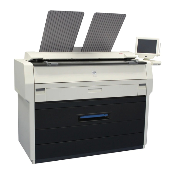
- Page 1 KIP 7170K Service Manual Version A.
- Page 2 Explanation for EMC 1. When this product is installed in North America. This product complies with part 15 of the FCC Rules. Operation is subject to the following two conditions: (1) This product may not cause harmful interference, and (2) this device must accept any interference received, including interference that may cause undesired operation.
- Page 3 Chapter 1 Introduction page 1. 1 Features 1- 2 1. 2 Specifications 1- 3 1. 2. 1 General 1- 3 1. 2. 2 Printer part 1- 4 1. 2. 3 Scanner part 1- 6 1. 3 Appearance 1- 7 1. 3. 1 Front 1- 7 1.
- Page 4 (9) Contactless IC card reader for more efficient accounting management (option) (10) KIP 7170 adopts 12.1 inch screen for the UI, wider than 10.4 for our old products. The capacitive multi-touch screen offers smooth, various and intuitive user operation that a pressure sensing device lacks.
- Page 5 1. 2 Specifications 1. 2. 1 General Subject Specification Model KIP 7170 Configuration Console Power consumption 1,440W (US model) (Maximum) 1,680W (EU / Asia model) (scanner / controller included) Power consumption Conformity with International Energy Star Program (Low power mode)
- Page 6 1. 2. 2. Printer part Subject Specification Printing method LED Array Electro photography Photoreceptor Organic Photoconductive Drum Print speed 80mm per second (Inch) 3.4ppm/E 5.8ppm/D Landscape (Metric) 3.3ppm/A0 5.6ppm/A1 Landscape Print head LED Array Resolution of print head 600dpi x 2400dpi Print width Maximum 914mm / 36”...
- Page 7 Subject Specification Media (Recommended Media) US model: Bond 64g/m to 80g/m , US Bond (PB-20) Vellum US Vellum (XV-20) Film 4MIL (PF-4DME) EU / Asia model: Plain Paper 64g/m to 80g/m Tracing Paper Gateway Tracing Paper (73g/m Film NSF4mil Storage of consumables (Toner cartridge) Store the cartridge within the temperature range from 0 to 35 degrees Centigrade and within the humidity range from 35...
- Page 8 1. 2. 3 Scanner part Subject Specification Scanning method Contact Image Sensor (CIS) (5 pieces of A4 sized CIS) Light source LED (R/G/B) Scanning speed Monochrome : 65mm/s (600 dpi, normal quality) Grayscale : 65mm/s (max) Color : 22mm/s NOTE : The actual speed may vary by the scan software. Setting of original Face up Starting point of scan...
- Page 9 Front (OPTION) Name Function Main Switch You can turn on/off the KIP 7170. Original Guides Feed the original under the Scanner Unit along the Original Guides. User Interface This is a Touch Screen, and many kinds of user operation are available.
- Page 10 For an optional device Service Use. 5VDC max. LAN Port Connect the LAN Cable to connect the KIP 7170 to the network. (Do not connect a telephone line) Dehumidify Heater Switch Turn on the Dehumidify Heater with this switch when you US model : OPTION would like to dry the paper in the humid season.
- Page 11 1. 4 Specifications for Scan Original A scan original must satisfy the following specifications. Thickness 0.05mm to 1.60mm Width 210mm to 914.4mm Length 210mm to 6,000mm NOTE : 1. Image quality for an original with 0.25mm or thicker is guaranteed only in a standard size even the scanner physically accepts it. 2.
- Page 12 1. 4. 3 “Do Not Scan” Originals It is impossible to use the following types of originals because they are likely to damage the scanner. Do not scan the following kinds of original, because you may damage the original or scanner itself! Sticked with paste Paste Torn...
- Page 13 Not square Wet image Made of metal or fabric Metal Fabric Rough surface (Carbon paper for example) Rough surface Clipped or stapled Clipped Stapled 1-11 K134sm1e1...
- Page 14 The following kinds of originals can be read with using a carrier sheet. However, the image quality and feed reliability are not guaranteed. Patched Punched 1-12 K134sm1e1...
- Page 15 1. 5 Specifications for Printing Media 1. 5. 1 Papers not available to use Do not use the following kinds of printing paper because you may damage the print engine! Excessively curled (a diameter of 50 mm or less) Folded Creased Torn Punched...
- Page 16 Paper that has already been used for printing Extremely sticky Extremely thin and soft Extremely slippery OHP Film CAUTION Do not use the paper with staple, or do not use such conductive paper as aluminium foil and carbon paper. Such paper may become cause for the fire. NOTE (1) Print image may become light if printed on a paper of rough surface.
- Page 17 High NOTE (1) KIP 7100 is equipped with the Dehumidify Heater (option for US model.) Using it in high humidity environment (65% or higher) is recommended. (2) “Void of image” and “crease of paper” will occur in case of extremely high or low humidity.
- Page 18 2- 2 2. 2. 1 Unpacking 2- 2 2. 2. 2 Confirmation of Accessories 2- 3 2. 3 Leveling KIP 7170 2- 5 2. 4 Setup of the Machine 2- 7 2. 5 Opening and Closing the LED Head Frame 2-13 2.
- Page 19 Keep ample space around the equipment to ensure comfortable operation. (Refer to the following figure.) The floor must be level and the strength must be ample to sustain the weight of the equipment. 30cm/12” or larger (Rear) KIP 7170 (Front) 80cm/32” or larger for Roll Deck 90cm/35.4” or larger for Paper Tray (option) *L+R=35cm/14”...
- Page 20 2. 2 Unpacking 2. 2. 1 Unpacking 1. Unwrap the machine. Put aside the following cardboard boxes. - Top : UI Unit Box (1), Accessory Box (2), empty Drum Box (3) -Scanner Cover (Inside) : Shading Sheet (4) - Roll Deck (Inside) : Exit Tray Box (5) Accessory Box UI Unit Box...
- Page 21 2. 2. 2 Confirmation of Accessories Confirm the following parts are attached to the product. Accessory Box Item name Picture Number Item name Picture Number of article of article Original 1 each Cap Assy Guide 1 & 2 Toner Power Cartridge Cord (400g)
- Page 22 Exit Tray Box Item name Picture Number Item name Picture Number of article of article Exit Tray Exit Tray 2 Others Item name Picture Number Item name Picture Number of article of article Shading Drum Box Sheet ( empty ) K134sm2e2...
- Page 23 2. 3 Leveling KIP 7170 1. Pull up the Lever 2 (1) to open the Engine. 2. Remove the screws (2) at both sides. 3. Remove 4 screws (3) at the bottom of both sides. 4. Remove 6 screws (4) at the back on both sides.
- Page 24 6. Close the Engine Unit. 7. Rotate 4 Leveling Bolts (7) on the bottom of the KIP 7170 with a wrench to bring up the KIP 7170 from the floor. Keep 85mm of distance between the bottom plate and the floor. (It is about 80mm before the adjustment.)
- Page 25 2. 4 Setup of the Machine 1. Draw out Roll Deck and remove tape (1) 2. Pull up on the Levers (1) to open the Engine. 3. Carefully remove the protection mat (3) under the Drum. 4. Open the Cover 4 (4). K134sm2e3...
- Page 26 5. Remove the screws (5) and flat washers (6) to release the Bands (7) at both sides. 6. Rotate up the Pins (8) and move them to the inside to pull them out from the holes. Remove the Cover 4 (4). 7.
- Page 27 8. Remove 4 pieces of screw (10). 9. Close the Bypass Feeder (9). Open the Developer Press Unit (11). 9. Disconnect the connector (12). 11. Remove 2 pieces of red screw (13) at both sides of the Developer Unit, which protect the Developer Unit from vibration during transportation.
- Page 28 12. Holding both side plates firmly, slide the Developer Unit (14) out of the machine. 13. Remove 1 label (15) on the toner supply hole of Toner Hopper. 14. Remove 8 labels (16)(17) to remove wrapping sheet (18). 15. The process unit and toner cover should be open. The Photoconductive Drum is covered with a black sheet (19). Gently remove it pulling from the front.
- Page 29 16. Install the Developer Unit (14) to the machine. Connect the connector (12). NOTE Both the Gear Helical 20T (20) on machine side and the Gear Helical 28T (21) on Developer Unit side must be in gear firmly with each other, but they may not be in gear with each other by just installing the Developer Unit to the machine. After installing the Developer Unit to the machine, rotate Gear Helical 34T (22: instead of Gear Helical 20T) by hand from under the Engine Unit.
- Page 30 18. Close the Engine Unit. 19. Both the LED Head and the Image Corona are locked with the screws (22) being separated from the Drum, not to be damaged during the transportation. Loosen 2 screws (22). This will release the Fix Bracket (23) to seat the LED Head / Image Corona in position. After that, pressing the Fix Bracket (23) from above, fix the screw (22).
- Page 31 2. 5 Opening and Closing the LED Head Frame To keep the proper gap between the LED Head and the Drum, make sure to open and close the LED Head Frame . According to this work, the gap between the LED Head and the Drum becomes the same level as the one before shipping and the more stable image quality can be maintained.
- Page 32 4. Open the Cover 4 (7). 5. Remove 4 pieces of 4x6 screw (8) and 2 pieces of washer screw (9). 6. Slide the Scanner Unit (10) fully backward. 2-14 K134sm2e3...
- Page 33 7. There are 2 pieces of Stopper (11) at both sides, which lock the LED Head Frame. Loosen the screw (12) and then slide the Stoppers (11) outside to unlock the LED Head Frame. 8. Open the LED Head Frame (13). NOTE The Stopper 2 (14) comes out automatically to prevent the LED Head Frame from falling down.
- Page 34 9. Close the LED Head Frame (13). NOTE When closing and fixing the LED Head Frame, please take the following steps orderly. The key point is to fix the left side of LED next, which achieves correct focus of LED Head Frame. Do not change the order of these Head Frame first then the right side steps.
- Page 35 Return the Scanner Unit (10) in position. 11. Fix the Scanner Unit with 4 screws (8) and 2 tooth washer screws (9). 2-17 K134sm2e3...
- Page 36 12. Close the Cover 4 (7) 13. Connect the connector (5) and then, fix the DC Harness and USB Cable with Wire Saddle (6). 14. Attach the Cover 10 (4) with 2 screws. 15. Close the Paper Exit Assy (Outside (1) & Inside (2)). 2-18 K134sm2e3...
- Page 37 2. 6 Installing Monitor 1. Insert 2 Tooth Washer Screws (1) into the screw hole on the right side frame of the machine. 2. Hook Monitor Assy (2) on the Tooth Washer Screws (1). Tighten 2 Tooth Washer Screws (1). 2-19 K134sm2e4...
- Page 38 3. Fix Monitor Assy with 2 Tooth Washer Screws (3) (4). NOTE Please use the screw driver which length is 24cm (9.4 inch) or shorter when tightening the screws (4). 24cm (9.4 inch) or shorter 2-20 K134sm2e4...
- Page 39 4. Connect USB Cable (5, for PANEL), VGA Cable (6) and Power Supply cable (7) to the concerning connectors of the machine frame. Then connect one more USB Cable (8, for external USB device). PANEL DATA NOTE Be sure to insert the USB plug of the USB Cables (5) (8) to the correct receptacles. First connect the monitor USB Cable (5) to the back of the 2 connectors on the machine.
- Page 40 2. 7 Installing Accessories 1. Install Exit Tray (1), Original Guide (2) and Exit Tray 2 (3). NOTE Install Exit Tray 2 (3) in the correct direction. The spine should face down. Side View Correc Wrong 2-22 K134sm2e5...
- Page 41 2. Open Cover 4 (4). 3. Shake Toner Cartridge (5) several times. After shaking, tilt the Toner Cartridge to the cap side. Cap Side 4. Keep pressing down the Cartridge Lock Lever (6). Direct the toner supply hole to the floor, fit the pin (7) on the left side of the cartridge to the groove (8) on the machine side.
- Page 42 5. Turn the body (9) of the cartridge in one revolution to the arrow direction to open the toner supply hole. Confirm that the projection (10) if fitted into the notch (11). NOTE It is not necessary to lock the cartridge with the Lever (12).
- Page 43 2. 8 Printer Setting When opening "SETTINGS" screen at an initial start-up of the printer, there are 6 items which are red. As the initial setup is required on these items, please set them by the followings. 1. Plug the power cord for the printer into a dedicated wall outlet. WARNING (1) Do not handle the Power Plug with wet hands, or you may receive an electrical shock.
- Page 44 2. Connect Power Cable and LAN Cable with the printer. LAN Cable Power Cable 3. Press “ ” side to turn on the printer. Press “ | ” side. 2-26 K134sm2e5...
- Page 45 4. “UI Home screen” appears. Press [ACCOUNTING]. 5. Touch the entry field of "User Name", and then select "Service" from the pull-down menu. Touch Service 6. Enter "kipsysk" in the password field, press the ENTER key, and then press [OK] in the LOG IN screen to log in with the administrative right.
- Page 46 7. Press [GUIDES]. 8. Press [Help]. 9. Press [Settings]. “SETTINGS” screen appears. 2-28 K134sm2e5...
- Page 47 10. Press [LANGUAGE]. Select a language. 11. Press [DATE & TIME]. Select your time zone in Time Zone region and then Press [OK]. 12. Press DATE & TIME again. Change Date and Time settings according to your region and then press OK.
- Page 48 13. Press [IPV4 SETUP] to perform a network setting. NOTE Depending on the network environment in which the printer is installed, "IPV6 SETUP" is sometimes used. For this case, please perform the network setting with "IPV6 SETUP". Please contact the network administrator about the network environment. 14.
- Page 49 15. If "Manual Setup" is selected, touch the entry screen, enter the IP Address with the software keyboard, and then press [Enter] Key. After that, press [OK] on the “SETTINGS” screen”. Touch Entry screen appears when [Manual Setup] is pressed. 16.
- Page 50 17. Enter the appropriate printer name, and then press [Enter] Key. ********** 18. When pressing [SAVE], the screen for restarting the controller appears. Press [RESTART]. The printer name is defined by this operation. 19. After rebooting the controller, open "SETTINGS" screen again, and then press [KEYCODE]. 2-32 K134sm2e5...
- Page 51 20. Press [Edit]. Touch the entry screen, enter "Key Code", and then press [SAVE]. Touch 21. If the entered key-code is correct, the corresponded option(s) is checked. Press [Close]. 2-33 K134sm2e5...
- Page 52 22. Press [TONER SETUP] and then press [Toner Setup]. Toner Setup Mode is the utility to supply toner powder from an installed Toner Cartridge to Developer Roller, and evens the toner level in it. It takes approximately 20 minutes to complete. Reference 1.
- Page 53 2. 9 Regional Setting Select a correct region according to the residential area. NOTE Selected regional setting will become effective when the printer is restarted by turning off/on the main switch. Regional setting is set to the following default values at shipment according to the destination of the product.
- Page 54 3. Press “Door Icon” to log in Maintenance GUI Home. 4. Press “Map” Icon in Maintenance GUI Home. 2-36 K134sm2e5...
- Page 55 5. According to your residential area, choose a correct regional code in the pull-down menu under and then press “OK” xx xxx CODE Residential area 00: --- No selection 01: NA North America & Canada 02: EUR EU & Russia 03: CLA Central America &...
- Page 56 7. Turn off the Printer, and turn it on again few seconds later. This will enable the selected regional setting. OFF / ON NOTE Selected regional setting will become effective when the printer is restarted by turning off/on the main switch. 8.
- Page 57 9. Press “ X “ button. Confirmation screen appears. Press [Yes]. 10. UI screen will display Home screen in a short time. 2-39 K134sm2e5...
- Page 58 2. 10. 1 Launching K129 Diag On the UI Home screen, press the Home icon and the status indication quickly in the following order to indicate the desktop screen. " KIP" icon (twice) Status indication (once) "KIP" icon (once) 2-40...
- Page 59 2. Open “Diagnostics” folder. 3. Double click [Hardware Utilities] and [K129 diag X.X.X.X.XX]. 2-41 K134sm2e6...
- Page 60 4. Run “K129 Diag”. Reference Other ways to run the "K129 Diag" are described on the next page. 2-42 K134sm2e6...
- Page 61 Reference 1. Contact your KIP partner for K129Diag.exe and save it to any available storage on your removable storage. Connect removable storage to UI monitor’s connector. Removable storage 2. Select “Removable Disk”, and then run “K129 Diag.exe”. Removable storage (G:)
- Page 62 2.10. 2 Stitching Adjustment NOTE BUD No.15 (stitch setting 1) should be temporarily set to OFF “0” during Stitching Adjustment. 1. Run K129 Diag. Click [BackupData] to recall “Backup Data” sub window. 2. Click [Receive] 2-44 K134sm2e6...
- Page 63 3. The current parameters are retrieved and displayed in the list. 4. Double click on the row No.15 “Stitch Setting 1”. 2-45 K134sm2e6...
- Page 64 5. In “FormInput” screen, Click [Virtual Keyboard] to display the screen keypad. 6. Type “0” with keypad, and then click [OK] on the bottom. 7. Click [OK] on the bottom. 2-46 K134sm2e6...
- Page 65 8. The setting change you have made is reflected to the list. It will turn blue. Click [Send] on the bottom. The setting change turns black. Now it is sent to the Main Board. 2-47 K134sm2e6...
- Page 66 9. To close “BackupData” sub window, click the X button at the upper right corner. 10. Clean Glass DCMNT with a soft cloth. 11. Set the Shading Sheet to the scanner noting the arrow direction. NOTE No skew insertion. Doing so may cause an incorrect calibration. 12.
- Page 67 13. Select “Stitching Adjustment” in the upper drop-down menu. 14. Click [Start] beside the upper drop-down menu. NOTE If an error message occurs; 1. Correctly set the Shading Sheet to the scanner. 2. Check for dirt on the Glass DCMNT and the Shading Sheet.
- Page 68 15. When the scanning is finished, two sub windows “Stitch Simulate” and “Stitch Adjust” appear. Enlarge “StitchAdjust” window. Enlarge “Stitch Adjust” window. 2-50 K134sm2e6...
- Page 69 16. There are 4 target signs at every border between the CIS. CIS 1 CIS 2 CIS 3 CIS 4 CIS 5 In “Stitch Adjustment” window, Select [Jump] menu, and then click [CIS1 to CIS2]. The display area will jump to the corresponding area on the scanned image. If “Jump”...
- Page 70 17. Confirm the Stitching Adjustment results. no misalignment vertical misalignment horizontal misalignment this may include vertical & horizontal misalignment at a time 18. Select [Jump] menu, and then click the other CIS borders to confirm the results. If all of the 4 targets have no misalignment, go to step 25. If any of the targets has an misalignment, go to step 19 and after for manual correction.
- Page 71 19. First, correct vertical misalignment as follows. 19-1. In “StitchSimulate” window, click the buttons (see below in blue frame) to change the setting value for “vertical” (see below in red frame), in order to move the image block vertically. vertical misalignment this may include vertical &...
- Page 72 20. Second, correct horizontal misalignment as follows. 20-1. In “StitchSimulate” window, click the buttons (see below in blue frame) to increase / decrease the setting value for “horizontal” (see below in red frame). This moves the image block horizontally. horizontal misalignment Do the same way for all the 4 targets at the CIS borders if needed.
- Page 73 21. The manual correction is reflected to “StitchAdjust” window directly. Reconfirm the manual correction result on the 4 targets. If there is still misalignment, go back to step 19 and 20 to remove it. NOTE Be sure to reconfirm the manual correction result. no misalignment 22.
- Page 74 23. In “StitchAdjust” window, select [Control] menu, and then click [Confirm-Scan] to make another scan. 24. The rescan result can be checked in “StitchAdjust” window. 25. Click the X button at the upper right corner to close “StitchAdjust” and “StitchSimulate” sub windows.
- Page 75 28. The current parameters are retrieved and displayed in the list. 29. Double click on the row No.15 “Stitch Setting 1”. 30. In “FormInput” screen, Click [Virtual Keyboard] to display the screen keypad. 2-57 K134sm2e6...
- Page 76 31. Type “4” with keypad, and then click [OK] on the bottom. 32. Click [OK] on the bottom. 2-58 K134sm2e6...
- Page 77 33. The setting change you have made is reflected to the list. It will turn blue. Click [Send] on the bottom. The setting change turns black. Now it is sent to the Main Board. 2-59 K134sm2e6...
- Page 78 2.10. 3 Creating Backup Data NOTE To easily recover the scanner in case of lost / crash of the BUDs, follow the instruction below to create a backup. If you have quitted Backup Data window in the previous section, click [Backup Data] in the home screen, click [Receive] 2-60 K134sm2e6...
- Page 79 1. Select “File” menu, and click “Save As.” 2. Specify the location to create a backup (csv), and then click [Save]. 2-61 K134sm2e6...
- Page 80 3. Click the X button to quit “BackupData” sub window and K129 Diag. 4. Run “Touch”. UI Home screen reappears. 5. Turn off the printer. After confirming that the controller is surely shut-down, turn on the printer again. (completed) 2-62 K134sm2e6...
- Page 81 Chapter 3 Print / Scan Process Page 3. 1 Print Process 3- 2 3. 1. 1 Characteristic of toner 3- 2 3. 1. 2 Each step of the print process 3- 3 3. 1. 2. 1 Erasing (Removal of negative electric charges) 3- 5 3.
- Page 82 3. 1. 1 Characteristic of toner The toner used for KIP 7170 has a characteristic to be charged “negative”, which tends to be attracted to a more “positive” object. Suppose that there are objects A and B, and the situation is as follows.
- Page 83 3. 1. 2 Each step of print process One cycle of print consists of the following 8 processes. 1. Erasing (Removal of negative electric charges) 2. Charge of Drum 3. Exposure 4. Development 5. Transfer 6. Separation 7. Drum Cleaning (Removal of remained toner) 8.
- Page 84 When the printer is going to stop after printing, or when the used Roll Deck is changed with other one, the KIP 7170 will take the “Toner Collection Process” to remove the remained toner and place back into the Developer Unit.
- Page 85 3. 1. 2. 1 Erasing (Removal of negative electric charges) As the first step of print cycle, it is necessary to remove the negative electric charges from the Drum, which have remained there after the former print cycle. The Drum has a characteristic to lose the negative electric charges if it is exposed to the light. So the Drum is rotated and evenly exposed to the light from the Eraser Lamp.
- Page 86 3. 1. 2 .2 Charge of Drum The Image Corona discharges negative electric charges which are given to the Drum. The surface of Drum becomes about -620V evenly as a result, which corresponds to the white area of the printed image pattern. The Grid Plate is also connected to the High Voltage Power Supply individually.
- Page 87 3. 1. 2. 3 Exposure According to the printed image pattern, the LED Head throws the light (740nm) onto some part of Drum which corresponds to the black area of printed image pattern. As the Drum has a characteristic to lose the negative electric charges if it is exposed to the light, this part of Drum surface loses the charges and its potential becomes about -20V.
- Page 88 3. 1. 2. 4 Development The Developer Roller, which is evenly covered with the toner, is contacted to the Drum because the Developer Unit is pressed to the Drum. (The width of contact point is about 5mm.) The Developer Roller is supplied with -180V+/-5V (CND Model : -200V+/-5V) during the print cycle. And both -620V area and -20V area exist on the Drum because the Electrostatic Latent Image has been formed in the former Exposure process.
- Page 89 Even if some toner has not been removed by the Cleaning Roller but remained on the -620V area of Drum (It corresponds to the white area of the print) in the later [3.1.2.7 Drum Cleaning], this toner is removed at the time of Development because it moves to the Developer Roller of which potential (-180V (CND Model : -200V)) is higher than that of Drum (-620V).
- Page 90 3. 1. 2. 5 Transfer The printing paper is charged positively as the Transfer Corona discharges positive electric charges from under the paper. The toner existing on the -20V area on the Drum will move to the printing paper because the potential of the paper comes to be higher than the Drum by the Transfer Process.
- Page 91 3. 1. 2. 6 Separation The printing paper is attracted to the Drum after the Transfer because the potential of paper is positive and that of Drum is negative. It is necessary for avoiding the jam to separate the paper from the Drum by removing the static force between them.
- Page 92 3. 1. 2. 7 Drum Cleaning (Removal of remained toner) Some amount of toner that has not been transferred onto the printing paper is remaining on the Drum. This remained toner will be removed by the Cleaning Roller. The Cleaning Roller is supplied with +450V (+/-5V), and there are some negative electric charges on the Drum at this time.
- Page 93 3. 1. 2. 8 Fusing After Transfer / Separation Processes, the printing paper is transported to the Fuser Unit by the Inner Transport Unit. The Fuser Unit mainly consists of the Fuser Roller and the Pressure Roller. The Fuser Roller is very hot, and the Pressure Roller is strongly pressed to the Fuser Roller by the spring.
- Page 94 3. 1. 3 Controlling the movement of toner in the Developer Unit There are 3 kinds of rollers called “Developer Roller”, “Regulation Roller” and “Toner Supply Roller” in the Developer Unit. Each roller is supplied with its own voltage. In the following list, the voltage of the Developer Roller (-180V (CND Model : -200V)) is measured against the ground.
- Page 95 Taking advantage of the difference of potentials among these rollers, the movement of toner is controlled in the Developer Unit as follows. 1. The Toner Supply Roller carries the toner toward the Developer Roller. 2. When the toner reaches the contact point of these rollers, therefore, it moves onto the Developer Roller.
- Page 96 5. The voltage of both sides of Regulation Roller is 0V as these parts are connected to the ground. It is higher than that of Developer Roller (-180V (CND Model : -200V)). When the toner reaches the contact point of these rollers, therefore, it moves onto the Regulation Roller.
- Page 97 3. 1. 4 Toner Collection Process As explained in [3.1.2.7 Drum Cleaning], the Cleaning Roller is supplied with +450V to remove the remained toner from the Drum during the print cycle. This toner gathered by the Cleaning Roller is returned to the Developer Unit in the following 3 cases.
- Page 98 3. The voltage supplied to the Developer Roller is also changed to +350V (+/-5V) in the Toner Collection Process. As the potential of Developer Roller becomes higher than that of Drum, toner on the Drum moves onto the Developer Roller. Then the toner is carried into the Developer Unit by both the Developer Roller and the Toner Supply Roller.
- Page 99 Reference Voltages supplied to Regulation Roller and Toner Supply Roller are changed also as follows. Name of roller Supplied voltage Developer Roller +350V +/-5V against the ground Regulation Roller -80V +/-5V against the Developer Roller Bias (Center) Regulation Roller 0V (Ground) (Both sides) Toner Supply Roller Same voltage with the Developer Roller Bias...
- Page 100 As the CND model machine does not use “Density Compensation Process”, it is set as “OFF”. Do not change this setting. On rare occasion, loss of image density may occur under a special usage. KIP 7170 has the ability to reduce such loss of image density and this enables to maintain a satisfactory image quality regardless of the machine usage.
- Page 101 It outputs the image data to the Controller through the USB 2.0. 4. Controller outputs the image data to the KIP printer through the USB 3.0 on copy, or it outputs to the Network PC through the LAN cable on Scan to File.
- Page 102 Positioning process of Image Block The scanner part of KIP 7170 reads the image of original with 5 - CIS (Contact Image Sensor). As these CIS are arranged in 2 rows, there occurs a vertical gap of image among the image blocks.
- Page 103 The Main PCB removes the vertical gap among the Image Block according to the positioning setting (Y offset) specified through K-129 Diag. The image data before the positioning process The image data after the positioning process (Y offset) 3-23 K134sm3e1...
- Page 104 Also the Main PCB removes the duplication of image pixels among the Image Blocks according to the positioning setting (X overlap) specified through K-129 Diag. The image data after the positioning process (Y offset) The image data after the positioning process (X overlap) 3-24 K134sm3e1...
- Page 105 Chapter 4 Electrical Page 4. 1 General Information 4- 2 4. 2 Electrical Components Location 4- 3 4. 2. 1 Right side 4- 3 4. 2. 2 Left side 4- 6 4. 2. 3 Back side 4- 7 4. 2. 4 LED Head Frame 4-11 4.
- Page 106 4. 1 General Information This machine is mainly controlled by a microcomputer, which is located on DC Controller. This microcomputer reads input signals from sensors, and outputs the operation signals to motors, SSRs, solenoid, clutches and blowers on programmed timing. Sensor Driver DC Load...
- Page 107 4. 2 Electrical Components Location 4. 2. 1 Right Side Item Symbol Signal name Name Type Function (POWER-OFF) Switch AJ8R2004BBCF Turning on and off the machine Switch FA1L-AA22 Shuts off the AC power to the DCP1 when Toner Hatch or the right side of Engine Unit is opened SSR1 Solid State Relay...
- Page 108 (120V model) (230V model) K134sm4e1...
- Page 109 Item Symbol Signal name Name Type Function DCP1 DC Power Supply LEB225F- Outputting each 24VDC, 5VDC 0524-U and 0VDC Fuse Walter Protecting the 24VDC from the TSC3.15AH over-current If you replace the fuses, make LITTLE sure to use one listed left. 0215 3.15MXP Switch (Option) SDDJE1...
- Page 110 4. 2. 2 Left Side Item Symbol Signal name Name Type Function PW13420 PW13420 PCB Assy PW13420 Overall sequence control PW6654-02B PW6654 02B PCB Assy PW6654-02B Driver for the motors, clutches and so on Switch V-162-1C25 Detecting whether or not the Toner Hatch or the left side of Engine Unit is opened (The machine does not shut off...
- Page 111 4. 2. 3 Back Side Item Symbol Signal name Name Type Function Blower D12F-24BL 05 Assisting to transport the paper on the Inner Transport Unit ASFN90372 90 Cooling down the IPS Controller DCP2 DC Power Supply ZWS75BAF12 Supplying the DC power to both the UI and the PW11724.
- Page 112 (Fuser Unit omitted) Item Symbol Signal name Name Type Function ASFN60372 Supporting media feeding approach ASFN60372 Supporting media feeding approach K134sm4e1...
- Page 113 Item Symbol Signal name Name Type Function Switch FA2L-BA22 It stops supplying the AC power (Optional in USA) to the Dehumidify Heater when the Roll Deck is opened. K134sm4e1...
- Page 114 Item Symbol Signal name Name Type Function BL3 & BL4 HEAT_BL_L Blower D12F-24BL 05 Exhausting the inside air. HEAT_BL_R (They are equipped with the Ozone Filter.) Switch FA1L-AA22 Shuts off the AC power to the DCP1 when the right side of Heater Hatch is opened.
- Page 115 4. 2. 4 LED Head Frame Item Symbol Signal name Name Type Function PW6631 Eraser PCB A PW6631 Removing the negative electric charges from the Drum at the beginning of the Print Process 4-11 K134sm4e1...
- Page 116 (Image Corona Unit removed) Item Symbol Signal name Name Type Function LED HEAD LED Head Assy LH6604 Creating latent Images on Drum (53TRK x 3pcs.) PW6693 HV-ZD Assy PW6693 Keeping the Grid Voltage constant (Control of the surface potential) 4-12 K134sm4e1...
- Page 117 4. 2. 5 Main Frame (Drum removed) Item Symbol Signal name Name Type Function PW6631 Eraser PCB A PW6631 Assisting the paper separation by removing the electric charges from the Drum at the time of Separation Process DENS-S PH11 Toner Density Sensor GP2Y40010K0 Detecting the toner density on the drum surface.
- Page 118 Item Symbol Signal name Name Type Function PRESS_M Motor Set Geard 20-04301 Pressing the Developer Unit to 9J06M10301 the Drum (Or keeping the Developer Unit away from the Drum) PRESS_S Sensor GP1A73LCS2F Detecting the Developer Unit is (Or GP1A73A000J) pressed or kept away REGIST_S Sensor PS117ED1...
- Page 119 Item Symbol Signal name Name Type Function DOOR- Switch CS1A-B2CA Detecting the Roll Deck Open OPEN Error 4-15 K134sm4e1...
- Page 120 4. 2. 6 Developer Unit Item Symbol Signal name Name Type Function TLS1 TONER_S Sensor TSP15DA10C- Detecting whether or not the toner exists in the Developer Unit TONER_M Motor Set Geard MA-D05-008 Driving the Toner Hopper to supply the toner to the Developer Unit KNC PCB PW13551...
- Page 121 4. 2. 7 Fuser Unit Item Symbol Signal name Name Type Function Thermostat CH-152-35- Preventing over-heat Thermistor FS-K0113 Detecting the temperature on the central area of Fuser Roller Thermistor 3 FS-K0115 Detecting the temperature on the driven side of Fuser Roller 4-17 K134sm4e2...
- Page 122 Item Symbol Signal name Name Type Function Lamp Heating up the central part of 120V : Z166800001 Fuser Roller 230V : Z166800003 Lamp Heating up the right and the left 120V : Z166800002 part of Fuser Roller 230V : Z166800004 HEAT_EXIT Sensor GP1A73A000J...
- Page 123 Item Symbol Signal name Name Type Function STACK_SL Solenoid STC-SN10E Deciding print path to either top / rear PH15 STACK_S Sensor GP1A73LCS2F Detecting stacked prints (Or GP1A73A000J) PH16 STACKJ_S Sensor GP1A73A000J Detecting the paper mis-feed after Fuser Unit 4-19 K134sm4e2...
- Page 124 4. 2. 8 Roll Deck Item Symbol Signal name Name Type Function FEED_CL Clutch MIC5NE-45 Feeding the roll paper from both Roll 1 and Roll 2 R1FD_CL Clutch MIC8NE-23 Feeding the Roll 1 forward R1BK_CL Clutch MIC8NE-09 Rewinding the Roll 1 R2FD_CL Clutch MIC8NE-23...
- Page 125 (Dehumidify Heater: option for US model) Item Symbol Signal name Name Type Function Resister 120V 1K 15W Dehumidifying the roll paper 230V 3.5K Thermostat 2455RM-158- Controlling the temperature of Resister (The Resisters turn on when the Thermostat detects some decided temperature, and they turn off when it detects another decided temperature.) 4-21...
- Page 126 Item Symbol Signal name Name Type Function R_EDGE Sensor PS117ED1 Detecting the trailing edge of the roll paper R1SET_S Sensor PS117ED1 Detecting the set of Roll 1 PH12 FEED_ENC Sensor GP1A73LCS2F Detecting the length of the (Or GP1A73A000J) proceeding paper to be cut R2SET_S Sensor PS117ED1...
- Page 127 4. 2. 9 Cutter Unit Item Symbol Signal name Name Type Function Cutter Motor Moving the Cutter Blade Cutter Home Position Detecting the Home Position of Sensor Cutter Blade. 4-23 K134sm4e2...
- Page 128 4. 2. 10 Inner Transport Unit Item Symbol Signal name Name Type Function STRIP_S Sensor GP1A73A000J Detecting the paper mis-feed at the Separation Area 4-24 K134sm4e2...
- Page 129 4. 2. 11 Scanner Unit Item Symbol Signal name Name Type Function PW12930-01 LED DISPLAY BOAD PW12930-01 Indicates the scanner’s status. green: Ready ASSY green to-and-fro: Scanning red: Error red flashing: Cover Open, Jam PW12975-01 SW CONTROL PW12975 01 Has 2 switches for user BOARD ASSY Intervention “Stop/Eject”...
- Page 130 PW12920-02 Converts the analog data sent by (Data Controller PCB) CIS into digital data. Then takes some image processes to the digital data and sends it to KIP Printer via USB cable. S_PH8 Sensor LG248BL1 Detects whether Upper Unit is opened.
- Page 131 Item Symbol Signal name Name Type Function CIS Sensor FL06G-W07 Reads the image of original, and then send the analog data to D CON (Data Controller PCB). S_PH1 Sensor PS122GD4-A Detects the original to be inserted. Detects original width A4 (Portrait) S_PH2 Sensor PS122GD4-A...
- Page 132 Item Symbol Signal name Name Type Function Motor 103H7123-5746 Transports the original. S_PH9 Sensor LG248BL1 Detects rotations of FEED ROLLER 4-28 K134sm4e2...
- Page 133 4. 3 Check & Adjustment of Analog Output from HV Power Supply 4. 3. 1 Situations necessary to check the analog output It is necessary to check the analog output from High Voltage Power Supply after replacing the following parts. PW13420 PCB (DC Controller) HV Power Supply PCB (EUK1MGA60HA) Please check the analog output for each of the following part, and please adjust if it is out of the...
- Page 134 4. 3. 2 Analog Voltage to Image Corona The standard value of the voltage outputted from the HV Power Supply PCB to the Image Corona 1.30 +/-0.05V. Check and adjust the output current in the following way. 1. Connect the “+” cable of the multi-meter to the “CP11” pin on the HV Power Supply PCB (EUK1MGA60HA).
- Page 135 3. Adjust the output voltage if it does not satisfy 1.30 +/-0.05V. To adjust it, rotate the VR101 with a screwdriver. VR101 multimeter (DC) 4-31 K134sm4e3...
- Page 136 4. 3. 3 Analog Voltage to Transfer Corona The standard value of the voltage outputted from the HV Power Supply PCB to the Transfer Corona is specified to each type of paper as follows. Plain paper 1.20 +/-0.05V Tracing paper 1.00 +/-0.05V Film 1.00 +/-0.05V...
- Page 137 2. Select the Test Print Mode, and make a test print using each type of paper (plain paper, tracing paper & Film) making reference to [8. 3 Pattern Print]. As the high voltage is supplied to the Transfer Corona during the Test Print, check the voltage with the multi-meter.
- Page 138 4. 3. 4 AC Component to Separation Corona The standard value of the AC Component outputted from the HV Power Supply PCB to the 5.00 +/-0.05V. Separation Corona is Check and adjust the AC Component in the following way. 1. Connect the “+” cable of the multi-meter to the “CP31” pin on the HV Power Supply PCB (EUK1MGA60HA).
- Page 139 3. Adjust the AC Component if it does not satisfy 5.00 +/-0.05V. To adjust it, rotate the VR302 with a screwdriver. multimeter (DC) VR302 4-35 K134sm4e3...
- Page 140 4. 3. 5 DC Component to Separation Corona The standard value of the DC Component outputted from the HV Power Supply PCB to the -250 +/-5V. Separation Corona is Check and adjust the DC Component in the following way. 1. Connect the “+” cable of the multi-meter to the “CP33” pin on the HV Power Supply PCB (EUK1MGA60HA).
- Page 141 3. Adjust the DC Component if it does not satisfy -250 +/-5V. To adjust it, rotate the VR303 with a screwdriver. VR303 multimeter (DC) ground 4-37 K134sm4e3...
- Page 142 4. 3. 6 Negative Developer Bias to Developer Roller The Negative Developer Bias means the voltage supplied to the Developer Roller during the Print Cycle. The standard value of the Negative Developer Bias is as follows for each type of paper. Plain paper -180 +/-5V against the ground (-200 +/-5V : CND Model) Tracing paper...
- Page 143 2. Make a Test Print making reference to [8. 3 Pattern Print]. As the Negative Developer Bias is supplied to the Developer Roller during the Test Print, check the voltage with the multi-meter. The standard value of the Negative Developer Bias for each type of media is: Plain paper -180 +/-5V against the ground (-200 +/-5V : CND Model) Tracing paper...
- Page 144 4. 3. 7 Positive Developer Bias to Developer Roller The Positive Developer Bias means the voltage supplied to the Developer Roller during the Cleaning Cycle. 0.350 +/-0.005V against the CP42. The standard value of the Positive Developer Bias is Check and adjust the Negative Developer Bias in the following way. 1.
- Page 145 2. Make a Test Print making reference to [8. 3 Pattern Print]. The Positive Developer Bias is supplied to the Developer Roller for some seconds after the printed paper has been ejected. Check the voltage with the multi-meter during that period. The standard value of the Positive Developer Bias is 0.350 +/-0.005V against the CP42.
- Page 146 4. 3. 8 Bias gap between Developer Roller and Regulation Roller The standard value of the Bias gap between Developer Roller and Regulation Roller is +/-5V. Check and adjust it in the following way. 1. Connect the “+” cable of the multi-meter to the “OUTPUT3” pin on the HV Power Supply PCB (EUK1MGA60HA).
- Page 147 3. If the value (voltage) is “120 +/-5V” or “160 +/- 5V”, Regulation Bias may be automatically adjusted by Density Compensation Process. (As the CND model machine does not use “Density Compensation Process”, it is set as “OFF”.) “0006 Bias3 Count” Enter [Clear/Reset] “2”...
- Page 148 4. 3. 9 Positive Cleaning Roller Bias (Print Cycle) The Positive Cleaning Roller Bias means the voltage supplied to the Cleaning Roller during the Print Process. +450 +/-5V. The standard value of the Positive Cleaning Roller Bias is Check and adjust it in the following way. 1.
- Page 149 3. Adjust the Positive Cleaning Roller Bias if it does not satisfy +450 +/-5V. To adjust it, rotate the VR001 with a screwdriver. multimeter (DC) ground VR001 4-45 K134sm4e3...
- Page 150 4. 3.10 Negative Cleaning Roller Bias (Toner Collection Process) The Negative Cleaning Roller Bias means the voltage supplied to the Cleaning Roller during the Toner Collection Process, which is done after the completion of Print Process. The standard value of the Negative Cleaning Roller Bias is -550 +/-5V.
- Page 151 3. Adjust the Negative Cleaning Roller Bias if it does not satisfy -550 +/-5V. To adjust it, rotate the VR002 with a screwdriver. multimeter (DC) VR002 ground 4-47 K134sm4e3...
- Page 152 Chapter 5 Mechanical page 5. 1 Outer Covers 5- 1 5. 1. 1 Removal of Side Covers 5- 1 5. 1. 2 Removal of Cover 15 5- 3 5. 1. 3 Removal of Top Cover 5- 4 5. 2 Developer Unit 5- 6 5.
- Page 153 5. 6 LED Head 5-179 5. 6. 1 Replacement of the LED Head Unit 5-179 5. 6. 2 LED focus adjustment 5-192 5. 6. 2. 1 Check of the Test Pattern Image 5-192 5. 6. 2. 2 Positioning of the Aluminum Blocks 5-193 5.
- Page 154 5. 1 Outer Covers 5. 1. 1 Removal of Side Covers 1. Remove 2 pieces of Exit Tray (1) and Exit Tray 2 (2). 2. Pull up the Lever 2 (3) to open the Engine Unit. 3. Remove the screws (4) at both sides. K134sm5e2...
- Page 155 4. Remove 4 pieces of screw (5) at both sides. 5. Remove 6 pieces of screw (6) at both sides. 6. Remove both Cover 2 (7) and Cover 3 (8). K134sm5e2...
- Page 156 5. 1. 2 Removal of Cover 15 1. Remove 4 pieces of screw (1), loosen 4 pieces of screw (2), and then remove the Cover 15 (3). K134sm5e2...
- Page 157 5. 1. 3 Removal of Top Cover 1. Remove 2 pieces of Exit Tray (1) and Exit Tray 2 (2). 2. Remove 4 screws (3) on the back. 3. Lift up both sides of the Upper Unit (4). Lift up here. Lift up here.
- Page 158 5. Disconnect 1 connector (7). 6. Remove 4 screws (8) on the front. 7. Remove the Top Cover (9). NOTE For reassembling, fit the front end of the Top Cover to the Upper Unit. K134sm5e2...
- Page 159 5. 2 Developer Unit 5. 2. 1 Removal of the Developer Unit 1. Remove 2 pieces of Exit Tray (1) and Exit Tray 2 (2). 2. Open the Cover 4 (3). 3. Remove the 4x6 screws and washers (4) at both sides to make the Bands (5) free. K134sm5e3...
- Page 160 4. There are Pins (6) at both sides. Pull them up and then slide them inward to remove the Cover 4 (3). 5. Pull up the Lever 2 (7) to open the Engine Unit. NOTE It is impossible to remove the Developer Unit if the Engine Unit is closed, because the driving gears are firmly locked when closed.
- Page 161 7. Remove 4 pieces of 4x8 screw (9). 8. Close the Bypass Feeder (8), and then open the Developer Press Unit (10). 9. Disconnect the connector (11). Holding both Side Plates (12), remove the Developer Unit (13) from the machine. NOTE If you replace the whole Developer Unit, it is necessary to adjust the space between developer driving gears.
- Page 162 5. 2. 2 Replacement of Recommended Periodic Replacement Parts NOTE (1) A periodic replacement for the following parts is recommended. This section shows how to replace all of them in one sequent operation. Refer to this section as well for replacement individual part listed below. Item Number Remarks...
- Page 163 3. Remove 4 pieces of 4x6 screws (2) to remove the Hopper Assembly (3). 4. Remove 3 pieces of M4x6 screws (4) to remove Cover (5). 5. Remove Separator (6). 5-10 K134sm5e3...
- Page 164 6. Remove 4 pieces of 4x6 screw (7) to remove Scraper Assembly (8). 7. Loosen 10 screws (9) to remove Scraper from Scraper Assembly. old Scraper NOTE Just loosen the screws as little as possible to remove Scraper. Doing so will reduce the new Scraper’s wave. 5-11 K134sm5e3...
- Page 165 8. Put Scraper (10) in Scraper Assembly (8) and push Scraper’s edge to the inside. Scraper (10) should be placed that the numbers printed on one side face can be read in correct orientation. NOTE Visually check that Scraper’s bottom edge touches the round boss through the bracket’s opening.
- Page 166 10. Tighten the screws from the center to the sides with holding around each screw on the bracket. Secure center to side Secure center to side NOTE Be sure to check for wave on Scraper’s edge. If there is, go back to step 7 to install Scraper again.
- Page 167 14. Remove all the toner from Developer Unit. NOTE Do not reuse the removed toner. 15. On the driving side, remove Retaining Ring-C (11: C6) to remove Gear Helical 30T (12), Parallel Pin (13: 2.5x10) and Collar 3 (14) from Blade Roller shaft. NOTE Blade Roller (15) is pressed onto / released from Developer Roller (16) by Bracket 4 (17) (on the driving side) and Bracket 5 (18) (on the electrode plate side).
- Page 168 16. Remove 5 screws (19: M4x8) (20: M4x6) to remove Pin 4 (21), Plate 9 (22), Collar (23). 17. Remove Washer (24: 8.1x14x0.5t) and Gear 29T-34T Assy (25) 18. Remove Gear Helical 30T (26) and Parallel Pin (27: 3x20) from Toner Supply Roller shaft. If you cannot remove Parallel Pin (27) at this time, remove it after the later step 15.
- Page 169 19. Remove Retaining Ring-E (28: E7) to remove Washer (29: 8.1x12x0.2t) and Gear Helical 28T Assy (30). 20. Remove Retaining Ring-E (31: E10) to remove Washer (32: 12.2x20x0.5t) and Counter Roller (33) from Developer Roller shaft. 21. Remove 2 screws (34: M4x8) to remove Bracket 4 (17) and Spring (35). At this time, Blade Roller on the driving side will be released from Roller Developer by unsecured Bracket 4 (17).
- Page 170 23. Remove 3 screws (38: M4x6) and 2 Retaining Ring-E (39: E10) to remove Collar (40) and Bracket 10 Assy (41). 24. Remove Gear Helical 30T (42) and Parallel Pin (43: 3x16) from Toner Supply Roller shaft. 25. Remove Washer (44: 12.1x20x0.2t), Gear Helical 25T (45), Parallel Pin (46: 3x16), Counter Roller (47) from Roller Developer shaft.
- Page 171 26. Remove 2 screws (48: M4x6) to remove Bracket 5 (18) and Spring (49). At this time, Blade Roller on the electrode plate side will be released from Roller Developer by unsecured Bracket 5 (18). 27. Loosen 2 screws (50) to remove Bracket 19 (51). 28.
- Page 172 30. Remove Blade Roller (15) from Developer Unit. Do not install the new Blade Roller at this time. 31. On the driving side, remove 3 screws (60: M4x6) and Retaining Ring-E (61: E10) to remove Washers (62: 12.2 x 20 x 0.5t), Bracket 8 Assy (63). 32.
- Page 173 33. Remove Roller Developer (16). Do not install the new Roller Developer at this time. 34. On each side, remove Seal 1 (67). Remove 1 screw (68) to remove Seal R2 Assy / Seal L2 Assy (69) and Support Bracket(70). 5-20 K134sm5e4...
- Page 174 35. On each side, remove Seal 23 (71: upper), Seal 4 (72: lower), Seal 3 (73: under). Replace Seal Seal 4 Seal 3 with new ones. NOTE Align the bottom end of Seal 3 (73) to the rib inside the side plate. Align the far ends of Seal 23 (71) and Seal 4 (72) to the top and bottom ends of Seal 3 (73) respectively.
- Page 175 36. Install the new Seal R2 Assy Seal L2 Assy (74), Support Bracket (70), Seal 1 (75). NOTE (1) Fit the positioning boss to the longer hole on Support Bracket (70). (2) Do not tighten the screws (68) so much as the seals (74) will be transformed. 5-22 K134sm5e4...
- Page 176 37. Apply the new Sheet 3 (76), Steet 4 (77) to both sides of the new Developer Roller. Keep water or grease away from between the sheets. 38. Install the new Developer Roller to Developer Unit and fix it with the bearings. NOTE (1) Note the installation direction.
- Page 177 NOTE (3) Push Roller Developer against Seal 1 on the electrode plate side (A) to hold and keep its original position when reassembling. (4) While installing toward (A) then (B), be careful not to damage Sheet 3 and Sheet 4 on Roller Developer shaft.
- Page 178 39. Reinstall Scraper Assembly. NOTE (1) For Scraper Assembly and Blade Roller, please reinstall Scraper Assembly first and then locate Blade Roller in position later. This will avoid making Scraper’s edge waving. (2) After reinstalling Scraper Assembly, check that neither Scraper (10) nor Seal 1 (75) flips up on both sides.
- Page 179 41. Install the new Blade Roller to Developer Unit and fix it with the brackets. NOTE (1) Note the installation direction. The longer shaft should be placed to the driving side. electrode plate side driving side (2) Seal 1 (75) on each side should be seated in position along the bosses. out of position Correct Wrong...
- Page 180 NOTE (5) After installing, check that Seal 1 (75), Sheet (78), Sheet 2 (79) are not damaged or deformed. (6) After locating, check that Scraper (10) is not wavy. (7) Blade Roller (15) is pressed onto / released from Developer Roller (16) by Bracket 4 (on the driving side) and Bracket 5 (on the electrode plate side).
- Page 181 43. Make sure that the 6 screws (48) (55) (34) (52) are installed loose. If not, loosen them. 44. On the electrode plate side, fully press down the top of Bracket 5 (18). With pressing, tighten 2 screws (48) to secure Bracket 5 (18). 45.
- Page 182 46. Press down the top of Bracket 7 Assy (59) and Bracket 6 Assy (54) at a time. This will allow Blade Roller to be seated in the correct position. NOTE (1) Press down both Bracket 7 Assy and Bracket 6 Assy at the same time. Pressing only one side may lose the correct pressure balance between the electrode plate side and the gear side.
- Page 183 48. Turn the screw (55) in just enough revolution so that its spring washer is held in the gap. spring washer on (55) released held 49. Turn the screw (52) in just enough revolution so that its spring washer is thrust in the gap. Do not turn it completely.
- Page 184 51. Slowly tighten the screw (52) to secure Bracket 6 Assy (54). NOTE Do not tighten the screw (52) (55) quickly at this point of time. Otherwise proper and even pressurization of Blade Roller between left/right may fail, and this will make the toner layer on Roller Developer get thicker than required.
- Page 185 55. Along the guide on the side plates, gently place Separator (6) on the added toner. Do not push it in. to be placed along the guide NOTE (1) Just put Separator (6) on the toner. It will be placed unseated. Do not push it completely at this time.
- Page 186 56. Insert Developer Handle (82) to the shaft of Roller Developer, and gently turn Developer Handle (82). Separator will sink in the toner. Turn Developer Handle (82) until Separator sinks in position. NOTE (1) Slowly turn Developer Handle. Otherwise the toner may spill out. (2) Make sure that Separator (6) completely sinks in position by a 1/2 or more rotation of Developer Handle.
- Page 187 58. Install Developer Handle (82) to Roller Developer shaft. Rotate Roller Developer several times so that the roller surface is covered with the toner. NOTE If the pressures of Blade Roller on either or both sides are weaker than required, the toner layer on the Developer Unit will be much thicker than required when you rotate the Roller Developer in the above procedure 53.
- Page 188 62. Touch the entry field of "User Name", and then select "Service" from the pull-down menu. Touch Service 63. Enter "kipsysk" in the password field, press the ENTER key, and then press [OK] in the LOG IN screen to log in with the administrative right. kipsysk 5-35 K134sm5e4...
- Page 189 64. Press [GUIDES]. 65. Press [Help]. 5-36 K134sm5e4...
- Page 190 66. Press [Settings]. “SETTINGS” screen appears. 67. Press [PRINTER SERVICE] on the “SETTINGS” screen. Scroll 5-37 K134sm5e4...
- Page 191 68. Press [LAUNCH]. 69. Press ”Door” Icon to log in Maintenance GUI. 70. Press [Clear / Reset]. 5-38 K134sm5e4...
- Page 192 71. Select [00006 Bias 3 Count] from “Clear/Reset” menu. Press [Edit]. 72. Confirmation screen appears. Press [Yes]. 5-39 K134sm5e4...
- Page 193 73. Input screen appears. “0” Input with On-screen Keypad. Press [Edit]. 74. "Reset of Bias Adjustment by Density Compensation Process" is completed. Press [OK]. NOTE The required value for the KIP7170 to reset Bias Adjustment by Density Compensation “0” Process is “0”...
- Page 194 5. 2. 3 Replacement of Roller Supply 1. Remove Blade Roller and Roller Developer from Developer Unit making reference to [5. 2. 2 Replacement of Developer Unit Components]. 2. Remove Retaining Ring-E (1: E10) to remove Bearing (2). 3. On the electrode plate side, remove Retaining Ring-E (3: E10) to remove Bearing (4). 4.
- Page 195 5. Remove 9 screws (5) to remove Frame 2 (6). 6. Remove 2 screws (7) to remove Bracket Assy (8). 5-42 K134sm5e5...
- Page 196 7. Remove Toner Supply Roller (9). NOTE (1) Sheet 6 (10), Sheet 5 (11), Seal R Assy or 12: reuse Seal L Assy (12) are attached on each side shaft of Roller Supply. Remove them from the old Roller Supply and then install them to the new Roller Supply.
- Page 197 5. 2. 4 Replacement of Screw Assy 1. Remove the Developer Unit (1) from the machine making reference to [5. 2. 1 Removal of the Developer Unit]. 2. Disconnect the connector (2). 3. Remove 4 pieces of 4x6 screws (3) which fix the Hopper Assembly (4). 4.
- Page 198 5. Remove Separator (5). 6. Remove all the toner from Developer Unit. NOTE Do not reuse the removed toner. 7. Remove 5 screws (6: M4x8) (7: M4x6) to remove Pin 4 (8), Plate (9), Collar (10). 8. Remove Retaining Ring-E (11: E7) to remove Spacer (12), Gear 16T-34T (13). 5-45 K134sm5e5...
- Page 199 9. Remove Retaining Ring-E (14: E5) (15: E7) to remove Washer (16), Gear 15T (17), Gear 16T (18) and Parallel Pin (19). 10. Remove Retaining Ring-E (20) to remove Washer (21) and Bush (22). 11. On the electrode plate side, remove 3 screws (23) to remove Holder 2 Assy (24). 12.
- Page 200 13. Remove Screw A Assy (28: near Roller Supply), Screw B Assy (29: far from Roller Supply). Remove Side Seal (30) and Washer (31) on both ends of Screw A Assy (28) and Screw B Assy (29). 5-47 K134sm5e5...
- Page 201 14. Remove each 2 screws (32: M3x5) to remove Screw A (33) / Screw B (34). NOTE When replacing Screw A (33) / Screw B (34), please note the followings. (1) Note the twisting direction around the shaft. (2) Each Screw A (33) / Screw B (34) has a 3 twist between the screws (32). (3) Screw A (33) / Screw B (34) are fragile.
- Page 202 15. Replace all the components except Separator (5) and Hopper Assy (4) in position. 16. Shake the Starting Toner Bottle (35) well, and evenly add the toner to Developer Unit. 5-49 K134sm5e5...
- Page 203 17. Along the guide on the side plates, gently place Separator (5) on the added toner. Do not push it in. to be placed along the guide NOTE (1) Be careful of the direction of Separator (5). Do not install it in the wrong direction. (2) Just put Separator (5) on the toner.
- Page 204 18. Insert Developer Handle (36) to the shaft of Roller Developer, and gently turn Developer Handle (36). Separator will sink in the toner. Turn Developer Handle (36) until Separator sinks in position. NOTE (1) Slowly turn Developer Handle. Otherwise the toner may spill out. (2) Make sure that Separator (5) completely sinks in position by a 1/2 or more rotation of Developer Handle.
- Page 205 5. 2. 5 Replacement of DC Motor 1. Remove 1 screw (1) to remove the Cover (2). 2. Remove 3 screws (3) to remove the Cover (4). 3. Disconnect the connector (3), remove 2 screws (4), and then remove the motor assembly (5). 5-52 K134sm5e6...
- Page 206 4. Remove the Joint R (6). 5. Remove 3 pieces of 3x20 screw (7) to remove the Bracket 19 (8). Replace the DC Motor (9) with the new one. 5-53 K134sm5e6...
- Page 207 5. 2. 6 Replacement of Sensor (TLS1) 1. Remove the Developer Unit (1) from the machine making reference to [5. 2. 1 Removal of the Developer Unit]. 2. Disconnect the connector (2), and remove 2 pieces of 3x6 screw (3) to remove the Sensor (4). Replace the Sensor (4) with the new one.
- Page 208 5. 2. 7 Replacement of KNC PCB 1. Remove 1 screw (1) to remove the Cover (2). 2. Remove 3 screws (3) to remove the Cover (4). 3. Disconnect the connector (5), remove 2 screws (6), and then remove the motor assembly (7). 4.
- Page 209 5. Remove 1 screw (14) to remove PCB Bracket (15). 6. Remove 2 screws (16) to remove KNC PCB (17) from PCB Bracket. Disconnect the connector (18), and then replace the new one. 5-56 K134sm5e6...
- Page 210 5. 2. 8 Adjustment of the space between gears (Necessary to adjust after replacing the Developer Unit) NOTE You do not have to adjust the space between gears basically as it has been adjusted in the factory. But please do it only when you replace the whole Developer Unit. The Developer Unit is driven by the Gear Helical 20T on the machine and the Gear Helical 28T on the Developer Unit.
- Page 211 1. Remove the Developer Unit (1) from the machine making reference to [5. 2. 1 Removal of the Developer Unit]. 2. Remove 2 screws (2) to remove each Bracket 32 (3) on the left and Bracket 33 (4) on the right. You will find Adjustment Plate (5) and Adjustment Plate 2 (6).
- Page 212 3. On the left side, add (or remove) as many Adjustment Plate (5) as required, cover them with the Bracket 32 (3), and then fix with 2 screws (2). NOTE The following 3 kinds of Spacers are used on the left side of the machine. Spacer Z053101200 (thickness is 0.05mm) Spacer 5...
- Page 213 4. On the right side, add (or remove) as many Adjustment Plate 2 (6) as required, cover them with the Bracket 33 (4), and then fix with 2 screws (2). NOTE The following 3 kinds of Spacers are used on the left side of the machine. Spacer 2 Z053101210 (thickness is 0.05mm) Spacer 6...
- Page 214 5. Put back the Developer Unit (1) to the machine. 6. There is Gear Helical 28T (7) on Developer Unit side. There is Gear Helical 20T (8) on Engine Unit, and also there is Gear Helical 34T (9) on Engine Unit. Gear Helical 28T (7) and Gear Helical 20T (8) are contacted each other when the Developer Unit is on the machine.
- Page 215 Holding the Gear Helical 28T (7) firmly with one hand, move the Gear Helical 34T (9) with another hand whether there is any mechanical play between Gear Helical 28T (7) and Gear Helical 20T (8). Hold the Gear Helical 28T with one hand. Move Gear Helical 34T (instead of Gear Helical 20T) with another hand.
- Page 216 5. 2. 9 Readjustment of the Pressure of Regulation Roller If the pressure of Blade Roller is weak, the toner layer on the Developer Unit will be much thicker than required when you rotate the Developer Roller. Pressurize the Blade Roller in the correct way as shown below in this case. (You will not be able to pressurize it successfully by the usual way of pressurization once a too thick toner layer is created.) To correct the pressure of Blade Roller against Developer Roller, remove the thicker toner layer on...
- Page 217 4. Remove the Hopper Assembly (4). 5. Remove 3 pieces of M4x6 screws (5) to remove Cover (6). 6. Remove 4 pieces of 4x6 screw (7) to remove Scraper Assembly (8). 5-64 K134sm5e7...
- Page 218 7. On the driving side, remove Retaining Ring-C (9: C6) to remove Gear Helical 30T (10), Parallel Pin (11: 2.5x10) and Collar 3 (12) from Blade Roller shaft. NOTE Blade Roller (13) is pressed onto / released from Developer Roller (14) by Bracket 4 (15) on the driving side, by Bracket 5 (16) on the electrode plate side.
- Page 219 8. Remove 5 screws (17: M4x8) (18: M4x6) to remove Pin 4 (19), Plate 9 (20), Collar (21). 9. Remove Washer (22: 8.1x14x0.5t) and Gear 29T-34T Assy (23) 10. Remove Helical 30T (24) and Parallel Pin (25: 3x20) from Toner Supply Roller shaft. If you cannot remove Parallel Pin (25) at this time, remove it after the later step 12.
- Page 220 11. Remove Retaining Ring-E (26: E7) to remove Washer (27: 8.1x12x0.2t) and Gear Helical 28T Assy (28). 12. Remove Retaining Ring-E (29: E10) to remove Washer (30: 12.2x20x0.5t) and Counter Roller (31) from Developer Roller shaft. 13. Remove 2 screws (32: M4x8) to remove Bracket 4 (15) and Spring (33). 14.
- Page 221 15. Remove 3 screws (36: M4x6) and 2 Retaining Ring-E (37: E10) to remove Collar (38) and Bracket 10 Assy (39). 16. Remove Gear Helical 30T (40) and Parallel Pin (41: 3x16) from Toner Supply Roller shaft. 17. Remove Washer (42: 12.1x20x0.2t), Gear Helical 25T (43), Parallel Pin (44: 3x16), Counter Roller (45) from Developer Roller shaft.
- Page 222 18. Remove 2 screws (46: M4x6) to remove Bracket 5 (16) and Spring (47). 19. Loosen 2 screws (48) to remove Bracket 19 (49). 20. On the driving side, remove 1 pan head screw (50: M4x8 W/ SW FW) to remove 1 flat washer (51: M4) and Bracket 6 Assy (52).
- Page 223 22. Remove Blade Roller (13) from Developer Unit. Clean Blade Roller if it gets dirty. NOTE (1) Be careful not to damage Sheet (58) and Sheet 2 (59) on Blade Roller shaft. (2) Note the installation direction. The longer shaft should be placed to the driving side. electrode plate side driving side (3) Seal 1 (60) on each side should be seated in position along the boss (61).
- Page 224 23. On Developer Roller (14), vacuum the toner around the contact point against Blade Roller (13). Vacuum toner stuck around the contact area NOTE If some toner remains on the surface of Roller Developer, the toner will cushion the pressure by Blade Roller.
- Page 225 25. Reinstall Blade Roller (13). NOTE (1) Note the installation direction. The longer shaft should be placed to the driving side. electrode plate side driving side (2) Seal 1 (59) on each side should be seated in position along the bosses. out of position Correct Wrong...
- Page 226 NOTE (5) After installing, check that Seal 1 (59), Sheet / Sheet 2 (on Blade Roller shaft) are not damaged or deformed. (6) After locating, check that Scraper (58) is not wavy. (7) Blade Roller (13) is pressed onto / released from Developer Roller (14) by Bracket 4 (on the driving side) and Bracket 5 (on the electrode plate side).
- Page 227 26. Replace all the components except Gear Helical 30T (10) and Hopper Assy (4) in position. 27. Make sure that the 6 screws (46) (53) (32) (50) are installed loose. 28. On the electrode plate side, fully press down the top of Bracket 5 (16).
- Page 228 30. Press down the top of Bracket 7 Assy (57) and Bracket 6 Assy (52) at a time. This will allow Blade Roller to be seated in the correct position. NOTE (1) Press down both Bracket 7 Assy and Bracket 6 Assy at the same time. Pressing only one side may lose the correct pressure balance between the electrode plate side and the gear side.
- Page 229 32. Turn the screw (53) in just enough revolution so that its spring washer is held in the gap. spring washer on (53) released held 33. Turn the screw (50) in just enough revolution so that its spring washer is thrust in the gap. Do not turn it completely.
- Page 230 35. Slowly tighten the screw (50) to secure Bracket 6 Assy (52). NOTE Do not tighten the screw (50) quickly at this time. Otherwise proper and even pressurization of Blade Roller between both the sides may be failed, and this will make the toner layer on Developer Roller get thicker than required.
- Page 231 38. Install Developer Handle (63) to Developer Roller shaft. Rotate Developer Roller several times so that the roller surface is covered with the toner. NOTE If the pressures of Blade Roller on either or both sides are weaker than required, the toner layer on the Developer Unit will be much thicker than required when you rotate the Roller Developer.
- Page 232 5. 3 Fuser Unit 5. 3. 1 Removal of Fuser Unit 1. Remove 2 pieces of Exit Tray (1) and Exit Tray 2 (2). 2. Pull up the Lever 2 (3) to open the Engine Unit. 3. Remove the screws (4) at both sides. 5-79 K134sm5e8...
- Page 233 4. Remove 4 pieces of screw (5) at both sides. 5. Remove 6 pieces of screw (6) at both sides. 6. Remove Cover 2 (7) and Cover 3 (8). 7. Disconnect 4 connectors (9). 5-80 K134sm5e8...
- Page 234 8. Open Exit Cover (10). 9. Remove 2 screws (11) to remove Exit Side Cover R / L (12). 10. Open 2 clamps (13) and disconnect 1 connector (14). 5-81 K134sm5e8...
- Page 235 11. On the left side (your right hand), remove 1 piece of KL Clip (15). 12. Slide Exit Cover (10) to the arrow direction (right hand side) to remove it from the machine. 13. Release the springs (16) on both sides. 14.
- Page 236 15. Remove 1 screw (18) to release the hinge bracket (19). 16. Firmly hold Fuser Cover (20). Slightly open it (A) and remove the hinge bracket (19). Slide Fuser Cover (20) to the arrow direction (left hand side) (B) to remove it from the machine. 17.
- Page 237 18. Open the Engine Unit. 19. Loosen 1 screw (23) to release the drive side of Fuser Unit. 20. Pull and remove Fuser Unit (24) from the machine. 5-84 K134sm5e8...
- Page 238 5. 3. 2 Reinstallation of Fuser Unit Reference This section shows Fuser Unit with Paper Exit Assy removed for clarification. 1. With Engine Unit open, fully mount Fuser Unit (1) to the machine 2. On the left side of the machine, rotate Pulley (2) counterclockwise to check the gear engagement between Fuser Unit and the machine.
- Page 239 3. Install the brackets (3) with the screws (4) (5). Tighten the lower one (4) and then the upper one (5). 5: second 4: first 4. Tighten the screw (6) to fix Fuser Unit (1) to the machine. 5. Reconnect the connectors (7). 6.
- Page 240 5. 3. 3 Replacement of Recommended Periodic Replacement Parts NOTE A periodic replacement for them is recommended. This section shows how to replace all of them in one sequent operation. Item Number Remarks of article Roller Fusing All of these parts are contained in “Fuser Maintenance Kit”...
- Page 241 4. Remove 4 pieces of screw (5) at both sides. 5. Remove 6 pieces of screw (6) at both sides. 6. Remove Cover 2 (7) and Cover 3 (8). 7. Disconnect 4 connectors (9). 5-88 K134sm5e8...
- Page 242 8. Open Exit Cover (10). 9. Remove 2 screws (11) to remove Exit Side Cover R / L (12). 10. Open 2 clamps (13) and disconnect 1 connector (14). 5-89 K134sm5e8...
- Page 243 11. On the left side (your right hand), remove 1 piece of KL Clip (15). 12. Slide Exit Cover (10) to the arrow direction (right hand side) to remove it from the machine. 13. Remove the 4x6 screw (16) to remove each Nail Stripping Assembly (17). NOTE When reassembling, fix Nail Stripping Assembly with the screw while holding Nail Stripping Assembly down.
- Page 244 14. Disassemble the Nail Stripping Assembly as the following photo. Replace the Nail Stripping (18) with the new one. 15. Release the springs (19) on both sides. 16. Remove 1 connector (20). 5-91 K134sm5e8...
- Page 245 17. Remove 1 screw (21) to release the hinge bracket (22). 18. Firmly hold Fuser Cover (23). Slightly open it (A) and remove the hinge bracket (22). Slide Fuser Cover (23) to the arrow direction (left hand side) (B) to remove it from the machine. 19.
- Page 246 20. Open the Engine Unit. 21. Loosen 1 screw (26) to release the drive side of Fuser Unit. 22. Pull and remove Fuser Unit (27) from the machine. 5-93 K134sm5e8...
- Page 247 NOTE To reinstall Fuser Unit, follow the instruction below. (1) With Engine Unit open, fully mount Fuser Unit (27) to the machine. (2) On the left side of the machine, rotate Pulley (28) counterclockwise to check the gear engagement between Fuser Unit and the machine. If the gears on Fuser Unit and Pulley (28) do not move together, the engagement may fail.
- Page 248 23. Disconnect the connectors (29). Remove 4 screws (30) to release IR Lamps (31). Remove 2 screws (32) to release the connector brackets. 24. Remove Cover (33) on both sides of Roller Fusing. Gently pull IR Lamps (34: red) (35: white) toward either way to remove them. 5-95 K134sm5e8...
- Page 249 NOTE (1) Do not touch the glass part of the Lamp with a bare hand. (2) Do not interchange the IR Lamps (34) (35). One with red connectors (34) should be installed to the media entrance side and the other with white connectors (35) to the media exit side.
- Page 250 26. On both sides, remove 4 KL Clips (38) to remove Arm 4 (39) and Arm 3 (40). 27. On the connector side, remove 1 screw (41) to remove Cover 2 (42). Disconnect the harness (43). 28. Remove 2 screws (44) to remove Bracket 6 Assy (45). 5-97 K134sm5e9...
- Page 251 29. On the gear side, remove 1 screw (46) to remove Bracket 20 (47). 30. Remove 2 screws (48) to remove Bracket 7 Assy (49). 31. Remove 2 screws (50) on the media exit side. 5-98 K134sm5e9...
- Page 252 32. On the connector side, loosen 1 screw (51) to release Bracket 2 (52). 33. On the gear side, loosen 1 screw (53) to release Bracket 3 (54). NOTE Reinstall Bracket 2 (52) and Bracket 3 (54) in the correct position. (1) Fully push to slide the bracket to the arrow direction so that the fold portion on the bracket will fit into the notch on Fuser Upper Unit.
- Page 253 34. On the media entrance side, remove 2 screws (55) to release Thermostat Bracket (56). 35. Turn Fuser Upper Unit (57) to the back. Lift Fuser Upper Unit (57) upward to remove it. 36. On the gear side of Fuser Upper Unit, remove Retaining Ring-E (58) to remove Gear 30T (59). 37.
- Page 254 38. Remove 2 screws (62) to remove Bearing Holder (63). 39. On the connector side of Fuser Upper Unit, remove 2 screws (64) to remove Bearing Holder (65). 40. On both sides, remove Bush (66). Replace Bush with new ones. 5-101 K134sm5e9...
- Page 255 41. Remove Roller Fusing (67). NOTE Install Roller Fusing to Upper Fuser Assy in the correct direction. One end with a cutting should be placed to the gear side. cutting 42. Remove 2 screws (68) to remove Collar (69) from Roller Fusing (70). Roller Fusing Replace with a new one.
- Page 256 43. On the media exit side of Fuser Lower Unit, remove 2 screws (71) to remove Guide Plate 2 Assy (72). 44. Remove 1 screw (73) to remove each Nail Lower Assy (74). 5-103 K134sm5e9...
- Page 257 45. Turn Nail Lower (75) to remove it from the bracket. Replace Nail Lower with a new one. 5-104 K134sm5e9...
- Page 258 5. 3. 4 Replacement of Roller Pressure 1. Remove 2 pieces of Exit Tray (1) and Exit Tray 2 (2). 2. Pull up the Lever 2 (3) to open the Engine Unit. 3. Remove the screws (4) at both sides. 5-105 K134sm5eA...
- Page 259 4. Remove 4 pieces of screw (5) at both sides. 5. Remove 6 pieces of screw (6) at both sides. 6. Remove Cover 2 (7) and Cover 3 (8). 7. Disconnect 4 connectors (9). 5-106 K134sm5eA...
- Page 260 8. Open Exit Cover (10). 9. Remove 2 screws (11) to remove Exit Side Cover R / L (12). 10. Open 2 clamps (13) and disconnect 1 connector (14). 5-107 K134sm5eA...
- Page 261 11. On the left side (your right hand), remove 1 piece of KL Clip (15). 12. Slide Exit Cover (10) to the arrow direction (right hand side) to remove it from the machine. 13. Release the springs (16) on both sides. 14.
- Page 262 15. Remove 1 screw (18) to release the hinge bracket (19). 16. Firmly hold Fuser Cover (20). Slightly open it (A) and remove the hinge bracket (19). Slide Fuser Cover (20) to the arrow direction (left hand side) (B) to remove it from the machine. 17.
- Page 263 18. Open the Engine Unit. 19. Loosen 1 screw (23) to release the drive side of Fuser Unit. 20. Pull and remove Fuser Unit (24) from the machine. 5-110 K134sm5eA...
- Page 264 NOTE To reinstall Fuser Unit, follow the instruction below. (1) With Engine Unit open, fully mount Fuser Unit (24) to the machine. (2) On the left side of the machine, rotate Pulley (25) counterclockwise to check the gear engagement between Fuser Unit and the machine. If the gears on Fuser Unit and Pulley (25) do not move together, the engagement may fail.
- Page 265 21. On the connector side, remove 1 screw (26) to release Bracket 10 Assy (27). 22. On the connector side, remove 1 screw (28) to remove Cover 2 (29). Disconnect the harness (30). 23. Remove 2 screws (31) on the media exit side. 5-112 K134sm5eA...
- Page 266 24. On both sides, remove 4 grip rings (32) to remove Arm 4 (33) and Arm 3 (34). 25. On the connector side, loosen 1 screw (35) to release Bracket 2 (36). 26. On the gear side, loosen 1 screw (37) to release Bracket 3 (38). 5-113 K134sm5eA...
- Page 267 NOTE Reinstall Bracket 2 (36) and Bracket 3 (38) in the correct position. (1) Fully push the bracket to the arrow direction so that the fold portion on the bracket will fit into the notch on Fuser Upper Unit. (2) The 2 positioning bosses locate the bracket. fold The bracket should not ride over them.
- Page 268 28. On the media exit side of Fuser Lower Unit, remove 2 screws (40) to remove Guide Plate 2 Assy (41). 29. Remove 2 screws (42) to remove Washer Special (43) and Guide Plate (44). NOTE When reassembling, make sure that the holes of Guide Plate fit the bosses on the bracket on both side.
- Page 269 30. Remove Pressure Roller (45) from the unit. 31. Remove Retaining Ring-C (46) to remove Collar (47) (48: only on the gear side), Bearing (49) from each shaft end of Roller Pressure (50). Replace Roller Pressure with a new one. (gear side) (connector side)
- Page 270 5. 3. 5 Fuser Pressure Adjustment (NIP width check) 1. Load a tracing paper roll in 36”/A0 width into any available Roll Deck. 2. Make a test print in pattern No.2 S(0) with the roll in 297mm length. 3. When the test print’s leading edge appears within 50mm at the exit cover, stop the print process by opening any cover.
- Page 271 5. 3. 6 Replacement of Thermistor (TH1, TH2) 1. Remove the Fuser Unit (1) from the machine making reference to [5. 3. 1 Removal of the Fuser Unit]. 2. Release the harness from the clamps (2). Remove the connectors (3: TH1, white) (4: TH2, black) from Bracket 10 Assy (5). 3.
- Page 272 4. Remove each 1 screw (7) to release Thermistor Assy (8: TH1, short harness) and Thermistor 3 Assy (9: TH3, long harness). 5. Remove 1 screw (10) to replace Thermistor (8: TH1) (9: TH2) with a new one. 8, 9 NOTE Be careful of the direction of Thermistor when reassembling.
- Page 273 5. 3. 7 Replacement of Thermostat (TS1, TS2) 1. Remove the Fuser Unit (1) from the machine making reference to [5. 3. 1 Removal of the Fuser Unit]. 2. Remove 2 screws (2: M4x6) to remove Thermostat Assy (3). 3. Remove 2 screws (4: M3x4) to remove the Thermostat (5). Replace the Thermostat (5) with the new one.
- Page 274 5. 3. 8 Replacement of Exit Sensor (PH3) 1. Remove 2 pieces of Exit Tray (1) and Exit Tray 2 (2). 2. Pull up the Lever 2 (3) to open the Engine Unit. 3. Remove the screws (4) at both sides. 5-121 K134sm5eB...
- Page 275 4. Remove 4 pieces of screw (5) at both sides. 5. Remove 6 pieces of screw (6) at both sides. 6. Remove Cover 2 (7) and Cover 3 (8). 7. Disconnect 4 connectors (9). 5-122 K134sm5eB...
- Page 276 8. Open Exit Cover (10). 9. Remove 2 screws (11) to remove Exit Side Cover R / L (12). 10. Open 2 clamps (13) and disconnect 1 connector (14). 5-123 K134sm5eB...
- Page 277 11. On the left side (your right hand), remove 1 piece of KL Clip (15). 12. Slide Exit Cover (10) to the arrow direction (right hand side) to remove it from the machine. 13. Release the springs (16) on both sides. 14.
- Page 278 15. Remove 1 screw (18) to release the hinge bracket (19). 16. Firmly hold Fuser Cover (20). Slightly open it (A) and remove the hinge bracket (19). Slide Fuser Cover (20) to the arrow direction (left hand side) (B) to remove it from the machine. 5-125 K134sm5eB...
- Page 279 17. Remove the harness (21) and remove the screw (22) to remove Exit Sensor Assy (23). Remove Exit Sensor (24) form Exit Sensor Assy (23). Replace Exit Sensor with a new one. 5-126 K134sm5eB...
- Page 280 5. 4 Roll Deck 5. 4. 1 Replacement of Cutter Assembly 1. Draw out the Roll Deck (1). 2. Remove 4 screws (2) to remove Cover 1 (3). NOTE Make sure to insert the hooking part to the slit as the following photo when you put back the Cover 1 (3).
- Page 281 3. Remove 7 screws (4) to remove Cover 14 (5). NOTE Make sure that the step part on the bottom side of Cover 14 (5) is inside the bottom frame. step frame 4. Disconnect the connector (6). Remove 1 screw (7) and remove the clamp (8) to release the core. 5-128 K134sm5eC...
- Page 282 5. Remove 2 screws on the front (9) to remove Cutter Assy (10). Replace the whole Cutter Assy with a new one. NOTE (1) Reuse the clamp (8) and the core for a new Cutter Assembly. (2) Put the Cutter Assembly with the Cutter Motor up. If you put it with the Cutter Motor down, you will break the Cutter Motor Harness.
- Page 283 5. 4. 2 Replacement of Clutches (CL3, CL4, CL5) of Roll 1 1. Draw out the Roll Deck (1). 2. Remove 7 screws (2) to remove Cover 14 (3). NOTE Make sure that the step part on the bottom side of Cover 14 (3) is inside the bottom frame. step frame 5-130...
- Page 284 3. Remove Retaining Ring-C (4) and disconnect the harness (5) to remove each Clutch (6: CL3) or Clutch (7: CL4). Replace Clutch with a new one. 6, 7 4. Remove 1 Bind Head Screw (8) and 1 Pan Head Screw (9), disconnect the harness (10) to remove Clutch (11: CL5).
- Page 285 5. 4. 3 Replacement of Clutches (CL6, CL7) of Roll 2 1. Draw out the Roll Deck (1). 2. Remove 3 screws (2) to remove Cover 16 (3). 3. Remove 1 Bind Head Screw (4) and 1 Pan Head Screw (5), disconnect the harness (6) to remove Clutch (7: CL6).
- Page 286 4. Remove 1 Bind Head Screw (8) and 1 Pan Head Screw (9), disconnect the harness (10) to remove Clutch (11: CL7). Replace Clutch with a new one. 5-133 K134sm5eC...
- Page 287 5. 4. 4 Replacement of Timing Belt 633 1. Draw out the Roll Deck (1). 2. Remove 4 screws (2) to remove Cover 1 (3). NOTE Make sure to insert the hooking part to the slit as the following photo when you put back the Cover 1 (3).
- Page 288 3. Remove 7 screws (4) to remove Cover 14 (5). NOTE Make sure that the step part on the bottom side of Cover 14 (5) is inside the bottom frame. step frame 4. Disconnect the connector (6). Remove 1 screw (7) and remove the clamp (8) to release the core. 5-135 K134sm5eC...
- Page 289 5. Remove 2 screws on the front (9) to remove Cutter Assy (10). Replace the whole Cutter Assy with a new one. 6. Open 6 wire saddles (12) and release 3 connectors (13) to release the harness (14). 7. Remove Retaining Ring-C (15) to remove Clutch (16: CL4). 8.
- Page 290 9. Remove 3 screws (19) to remove Bracket 32 (20). 10. Loosen 1 screw (21) to release Pulley 3 (22). Push Pulley 3 (22) to the arrow direction and fix it. Replace Timing Belt 633 (23) with a new one. NOTE You do not have to adjust the belt tension.
- Page 291 5. 4. 5 Replacement of Timing Belt 453 1. Draw out the Roll Deck (1). 2. Remove 7 screws (2) to remove Cover 22 (3). NOTE Make sure that the step part on the bottom side of Cover 22 (3) is inside the bottom frame. step frame 5-138...
- Page 292 3. Loosen 1 screw (4) to release Pulley 3 (5). Move Pulley 3 (5) upward and fix it the screw (4) to release Timing Belt 453. 4. Remove 1 Bind Head Screw (6) and 1 Pan Head Screw (7) to remove Bracket 12 (8). Replace Timing Belt 453 (9) with a new one.
- Page 293 5. 4. 6 Replacement of Timing Belt 330 1. Draw out the Roll Deck (1). 2. Remove 7 screws (2) to remove Cover 22 (3). NOTE Make sure that the step part on the bottom side step of Cover 22 (3) is inside the bottom frame. frame 3.
- Page 294 5. 4. 7 Replacement of Sensor (PH6, PH7, PH9, PH12) NOTE (1) When reassembling, fit a boss or nails on the sensor into holes on the sensor bracket. boss nails (2) When reassembling, fit positioning bosses on the frame (or the sensor bracket) into the corresponding holes.
- Page 295 3. Remove 8 screws (7) to remove Plate (8). 4. Remove 1 screw (9) to release the sensor bracket (10). Remove the connector (11) to remove the bracket (10). boss 5. Remove 1 screw (12: M3x6) and 2 KL Clips (13) to remove Shaft 4 (14) and Encoder 2 Assy (15).
- Page 296 6. Remove 1 screw (17) to release the sensor bracket (18). Remove the connector (19) and 1 screw (20) to replace Sensor (21: PH7) with a new one. boss boss boss 7. Remove 1 screw (22) to release the sensor bracket (23). Remove the connector (24) and t1 screw (25) to replace Sensor (26: PH9) with a new one.
- Page 297 5. 4. 8 Replacement of Sensor (PH8) 1. Draw out the Roll Deck (1). 2. Remove 7 screws (2) to remove Cover 14 (3). NOTE Make sure that the step part on the bottom side of Cover 14 (3) is inside the bottom frame. step frame 5-144...
- Page 298 3. Remove 1 screw (4) to release the sensor bracket (5). Remove 1 connector (6) to replace Sensor (7: PH8) with a new one. NOTE (1) When reassembling, fit a boss or nails on the sensor into holes on the sensor bracket. nails (2) When reassembling, fit the positioning boss on the frame into the notch on the bracket.
- Page 299 5. 4. 9 Replacement of Sensor (PH10) 1. Draw out the Roll Deck (1). 2. Remove 3 screws (2) to remove Cover 16 (3). 3. Remove 1 screw (4) to release the sensor bracket (5). Remove 1 connector (6) to replace Sensor (7: PH10) with a new one.
- Page 300 NOTE (1) When reassembling, fit a boss or nails on the sensor into holes on the sensor bracket. nails (2) When reassembling, fit the positioning boss on the frame into the notch on the bracket. boss 5-147 K134sm5eD...
- Page 301 5. 4. 10 Replacement of Dehumidify Heater (Roll 1) 1. Draw out the Roll Deck (1). 2. Move Slide Guide (2) toward the middle. 3. Remove 2 screws (3) to remove Cover 15 (4). 5-148 K134sm5eD...
- Page 302 2. Remove 7 screws (5) to remove Cover 22 (6). NOTE Make sure that the step part on the bottom side of Cover 22 (6) is inside the bottom frame. step frame 5. Disconnect 1 connector (7). 5-149 K134sm5eD...
- Page 303 6. Remove 6 screws (8) to remove Roll 1 dehumidifier casing (9). 7. Remove 2 screws (10) and 1 connector (11) from each Resistor (12). Replace Resistor (square type) with a new one. 5-150 K134sm5eD...
- Page 304 5. 4. 11 Replacement of Dehumidify Heater (Roll 2) 1. Draw out the Roll Deck (1). 2. Move Slide Guide (2) toward the middle. 3. Remove 2 screws (3). 4. Move Slide Guide (2) toward the far end. 5-151 K134sm5eD...
- Page 305 5. Remove 2 screws (4) to remove Slide Guide 2 R Assy (5). 6. Remove 1 screw (6) to move Cover 7 (7). 7. Disconnect 1 connector (8). 5-152 K134sm5eD...
- Page 306 8. Move Cover 4 (9) to the arrow direction to remove it. 9. Remove 3 screws (10) to remove Roll 2 dehumidifier casing (11). 5-153 K134sm5eD...
- Page 307 10. Disconnect 1 connector (12). Remove 2 screws (13). Remove and replace Resistor (square type) (14) with a new one. 5-154 K134sm5eD...
- Page 308 5. 5 Photoconductive Drum 5. 5. 1 Replacement of the Photoconductive Drum 1. Remove 2 pieces of Exit Tray (1) and Exit Tray 2 (2). 2. Pull up the Lever 2 (3) to open the Engine Unit. 3. Remove the screws (4) at both sides. 5-155 K134sm5eE...
- Page 309 4. Remove 4 pieces of screw (5) at both sides. 5. Remove 5 pieces of screw (6) at both sides. 6. Remove both Cover 2 (7) and Cover 3 (8). 7. Close the Engine Unit. 5-156 K134sm5eE...
- Page 310 8. Open the Paper Exit Assy (Outside (9) & Inside (10)). 9. Remove 2 screws (11) to remove Cover 10 (12). 10. Disconnect the connector (13), and open the wire saddles (14) to release the harness. 11. Open the Cover 4 (15). 5-157 K134sm5eE...
- Page 311 12. Remove 4 pieces of 4x6 screw (16) and 2 pieces of washer screw (17). 13. Slide the Scanner Unit (18) fully backward. 5-158 K134sm5eE...
- Page 312 14. There are 2 pieces of Stopper (19) at both sides, which lock the LED Head Frame. Loosen the screw (20) and then slide the Stoppers (19) outside to unlock the LED Head Frame. Lock position Unlock position 5-159 K134sm5eE...
- Page 313 15. Open the LED Head Frame (21). NOTE The Stopper 2 (22) comes out automatically to prevent the LED Head Frame from falling down. Press the Stopper 2 as the right photo if you will close the LED Head Frame. 16.
- Page 314 16. Remove 1 tooth washer screw (24: M4x8), and remove Plate 2 (25) and Pulley Gear (26). NOTE (1) Belt 4 (27) is automatically loosed with Engine Unit open. It will be strained with Engine Unit closed. (2) The tooth washer screw (24) has a tooth burr face washer of which burr face meets the composition surface.
- Page 315 17. Remove the Collar (28) from the left Drum Shaft. NOTE The new (spare) Drum Assembly does not include the Collar (28). So please reuse it. 18. There are 2 pieces of screw (29) on the left which fix the Block (30). Loosen these screws (29) and rotate the Block (30) as the arrow marks.
- Page 316 19. Similarly loosen 2 pieces of screw (31) on the right and rotate the Block 2 (32) as the arrow marks. 20. Remove Photoconductive Drum (33), and replace it with the new one. NOTE The Aluminium Block (30) and (32) maintain the focus of the LED Head. Therefore it is necessary to re-position them correctly after replacing the Photoconductive Drum.
- Page 317 5. 5. 2 How to fix the Aluminium Blocks There are Aluminium Blocks at both sides of the Drum Shaft. As they maintain the focus of LED Head, it is necessary to re-position them correctly after replacing the Photoconductive Drum. Aluminium Blocks Print out the Test Pattern No.3 to check if the Aluminium Blocks are fixed at the correct position.
- Page 318 There are Aluminium Blocks (A) (B) at both sides, and each of them is fixed with 2 screws (C) (D). Left side Right side Do as follows to fix the Aluminium Blocks correctly. a) Always fix the Aluminium Block of the left (A) first and then right (B). b) When you tighten 2 screws (C) (D) to fix each Aluminium Block, always tighten the lower one (C) first and then the upper one (D).
- Page 319 5. 5. 2. 1 Fixing Block with Drum Block Fix Tool 1. Rotate the left Block (1) fully to the arrow direction (A: to front) and also press it to the arrow direction (B: to outside). This will remove any gap between Block (1) and the side frame of the machine.
- Page 320 2. Loosen the screws (2) (3) in a (approximately) quarter turn to release Block (1). Check that no excessive backlash to sideways appears. 3. Similarly to step 1, rotate the right Block (4) fully to the arrow direction (C: to front) and also press it to the arrow direction (D: to outside).
- Page 321 5. On the left side, hook Drum Block Fix Tool (7) on between the pin (8) on the frame and the U- shape opening (9) of Block (1). Hook the rear hook (10) the rim of the U-shape opening (9) and the front hook (11) in the groove of the pin (8).
- Page 322 6. With pressing Block (1) down (E), slightly turn Block to the arrow direction (F) and release it to locate Block correctly by restoring spring. 7. Tighten the lower screw (2) and then the upper screw (3) to secure Block (1). 5-169 K134sm5eE...
- Page 323 8. Similarly to step 5, on the right side, hook Drum Block Fix Tool (7) on between the pin (12) on the frame and the U-shape opening (13) of Block (4). NOTE (1) Handle Drum Block Fix Tool with care. Be sure not to damage Drum or any other components when removing/attaching it.
- Page 324 9. Similarly to step 6, with pressing Block (4) down (G), slightly turn Block to the arrow direction (H) and release it to locate Block correctly by restoring spring. 10. Tighten the lower screw (5) and then the upper screw (6) to secure Block (4). 11.
- Page 325 5. 5. 2. 2 Fixing Block by hand (w/o Drum Block Fix Tool) 1. Rotate the left Block (1) fully to the arrow direction (A: to front) and also press it to the arrow direction (B: to outside). This will remove any gap between Block (1) and the side frame of the machine.
- Page 326 3. Put your finger inside the U-shape opening (4) of Block (1). Put the other finger on the pin (5) of the frame. Push the fingers toward each other (C: inside). Note that the entire Block (1) is shifted towards the pin (5) by the finger at the U-shape opening (4).
- Page 327 4. Similarly to step 1, rotate the right Block (6) fully to the arrow direction (D: to front) and also press it to the arrow direction (E: to outside). This will remove any gap between Block (6) and the side frame of the machine. With holding Block (6), tighten the screws (7) (8) just enough turn to fix Block (6) temporarily.
- Page 328 6. Similarly to step 3, put your finger inside the U-shape opening (9) of Block (6) and put the other finger on the pin (10) of the frame. Push the fingers toward each other (F: inside). Note that the entire Block (6) is shifted towards the pin (10) by the finger at the U-shape opening (9).
- Page 329 5. 5. 3 Cleaning of Photoconductive Drum 1. Remove the Photoconductive Drum from the machine making reference to [5. 5. 1 Replacement of the Photoconductive Drum]. 2. Wipe the surface of Photoconductive Drum with a dry cloth. 3. If the toner strongly sticks on the surface and it is impossible to remove it, wipe with the cloth impregnated with the alcohol.
- Page 330 5. 5. 4 Replacement of Belt 4 1. Remove 2 pieces of Exit Tray (1) and Exit Tray 2 (2). 2. Pull up the Lever 2 (3) to open the Engine Unit. 3. Remove 6 screws (4) to remove Cover 2 (5). 5-177 K134sm5eE...
- Page 331 4. Remove Belt 4 (4). NOTE Belt 4 is automatically unfastened if only you open the Engine Unit. 5-178 K134sm5eE...
- Page 332 5. 6 LED Head 5. 6. 1 Replacement of the LED Head Unit 1. Remove 2 pieces of Exit Tray (1) and Exit Tray 2 (2). 2. Pull up the Lever 2 (3) to open the Engine Unit. 3. Remove the screws (4) at both sides. 5-179 K134sm5eF...
- Page 333 4. Remove 4 pieces of screw (5) at both sides. 5. Remove 5 pieces of screw (6) at both sides. 6. Remove both Cover 2 (7) and Cover 3 (8). 7. Close the Engine Unit. 5-180 K134sm5eF...
- Page 334 8. Open the Paper Exit Assy (Outside (9) & Inside (10)). 9. Remove 2 screws (11) to remove Cover 10 (12). 10. Disconnect the connector (10), and open the wire saddles (11) to release the harness. 11. Open the Cover 4 (12). 5-181 K134sm5eF...
- Page 335 12. Remove 4 pieces of 4x6 screw (13) and 2 pieces of washer screw (14). 13. Slide the Scanner Unit (15) fully backward. 5-182 K134sm5eF...
- Page 336 14. There are 2 pieces of Stopper (16) at both sides, which lock the LED Head Frame. Loosen the screw (17) and then slide the Stoppers (16) outside to unlock the LED Head Frame. NOTE When closing and fixing the LED Head Frame, please take the following steps orderly. The key point is to fix the left side of LED Head Frame first then the right side next, which achieves correct focus of LED Head Frame.
- Page 337 15. Disconnect 2 connectors (18) (19). 16. Open the LED Head Frame (18). NOTE The Stopper 2 (19) comes out automatically to prevent the LED Head Frame from falling down. Press the Stopper 2 as the right photo if you will close the LED Head Frame.
- Page 338 17. Remove the 4x6 screw (20) to remove the Fixing Bracket (21) on the right. NOTE Fixing Bracket (21) is required only when the machine is in delivery or when it is moved long way from one place to another. Printer operates without problem even if this is removed. If you have no chance to move the machine from current installation place, therefore, it is recommended to keep it removed.
- Page 339 19. Move the Plate (23) to the right to release the pin (25) of Corona Block. Then remove the Image Corona Unit (26). 20. Remove 1 screw (27) to remove the Collar (28). NOTE Do not drop the Collar (28) into the machine when removing it. 5-186 K134sm5eF...
- Page 340 21. Remove 1 tooth washer screw (29) to remove Bracket (30). NOTE Surely hold the Bracket (30) by hand when removing the screw (29) so as not to drop it into the machine. 22. For removing the LED Head (31), catch both ends first. NOTE Do not hold or touch the lens array parts (32).
- Page 341 23. Move the LED head Unit leftward to pull out its 2 bars (33) on the right from the holes (34) on the right side plate of Movable Unit. 24. Move the right end of LED Head Unit a little frontward so that it is completely out of the Movable Unit.
- Page 342 26. There is a white roller (37) on the LED Tension Bracket on the left. At first put the left end of LED Head Unit on this white roller (37). Then press and hold the left end of unit in the directions of arrows (A) and (B) same time to push down both 2 tension springs, and slide the entire unit leftward to fit 2 bars (35) into the holes (36).
- Page 343 27. After confirming 2 bars (35) on the left are surely fitted into the holes, leave your hand from the LED Head Unit. 28. Catch the right end of LED Head Unit by left hand for ease of later operation. Catch the right end of unit by left hand.
- Page 344 29. Similar as you have done in the former step 26, at first put the right end of LED Head Unit on the white roller (38) on the LED Tension Bracket on the right. Then press and hold the right end of unit in the directions of arrows (A) and (B) same time to push down both 2 tension springs, and slide the entire unit rightward to fit 2 bars (33) into the holes (34).
- Page 345 5. 6. 2 LED focus adjustment (if necessary adjust density balance among 3 LED blocks) Please adjust the focus of LED Head after the replacement of LED Head. Also adjust it if you have lost the correct focus by some reason. Adjust the focus by the following 4 steps.
- Page 346 5. 6. 2. 2 Positioning of the Aluminium Blocks There are Aluminium Blocks at both sides of the Drum, which adjust the distance between LED Head and Drum. If the LED focus is not correct, at first it is necessary to place them at the correct positions in the following way.
- Page 347 3. Remove the screws (4) at both sides. 4. Remove 4 pieces of screw (5) at both sides. 5. Remove 5 pieces of screw (6) at both sides. 6. Remove both Cover 2 (7) and Cover 3 (8). 5-194 K134sm5eF...
- Page 348 7. Close the Engine Unit. 8. Open the Paper Exit Assy (Outside (9) & Inside (10)). 9. Remove 2 screws (11) to remove Cover 10 (12). 10. Disconnect the connector (13), and open the wire saddles (14) to release the harness. 5-195 K134sm5eF...
- Page 349 11. Open the Cover 4 (15). 12. Remove 4 pieces of 4x6 screw (16) and 2 pieces of washer screw (17). 13. Slide the Scanner Unit (18) fully backward. 5-196 K134sm5eF...
- Page 350 14. There are 2 pieces of Stopper (19) at both sides, which lock the LED Head Frame. Loosen the screw (20) and then slide the Stoppers (19) outside to unlock the LED Head Frame. NOTE When closing and fixing the LED Head Frame, please take the following steps orderly. The key point is to fix the left side of LED Head Frame first then the right side next, which achieves correct focus of LED Head Frame.
- Page 351 15. Open the LED Head Frame (21). NOTE The Stopper 2 (22) comes out automatically to prevent the LED Head Frame from falling down. Press the Stopper 2 as the right photo if you will close the LED Head Frame. 16.
- Page 352 17. Remove 1 tooth washer screw (24: M4x8), and remove Plate 2 (25) and Pulley Gear (26). NOTE (1) Belt 4 (27) is automatically loosed with Engine Unit open. It will be strained with Engine Unit closed. (2) The tooth washer screw (24) has a tooth burr face washer of which burr face meets the composition surface.
- Page 353 18. There are Aluminium Block (25: left) (26: right) and each of them is fixed with 2 screws (27). Left side Right side Do as follows to fix the Aluminium Blocks correctly. a) Always fix the Aluminium Block of the left (25) first and then right (26). b) When you tighten 2 screws (C) (D) to fix each Aluminium Block, always tighten the lower one (C) first and then the upper one (D).
- Page 354 19. Rotate the left Block (25) fully to the arrow direction (A: to front) and also press it to the arrow direction (B: to outside). This will remove any gap between Block (25) and the side frame of the machine. With holding Block (25), tighten the screws (28) (29) just enough turn to fix Block (25) temporarily.
- Page 355 20. Loosen the screws (28) (29) in a (approximately) quarter turn to release Block (25). Check that no excessive backlash to sideways appears. 21. Similarly to step 19, rotate the right Block (26) fully to the arrow direction (C: to front) and also press it to the arrow direction (D: to outside).
- Page 356 23. Fix Blocks with Drum Block Fix Tool (or by hand). Go to step 23-1 for using Drum Block Fix Tool. Go to step 24 for without Drum Block Fix Tool. 23-1. On the left side, hook Drum Block Fix Tool (32) on between the pin (33) on the frame and the U-shape opening (34) of Block (25).
- Page 357 23-2. With pressing Block (25) down (E), slightly turn Block to the arrow direction (F) and release it to locate Block correctly by restoring spring. 23-3. Tighten the lower screw (28) and then the upper screw (29) to secure Block (25). 5-204 K134sm5eF...
- Page 358 23-4. Similarly to step 23-2, on the right side, hook Drum Block Fix Tool (32) on between the pin (37) on the frame and the U-shape opening (38) of Block (26). NOTE (1) Handle Drum Block Fix Tool with care. Be sure not to damage Drum or any other components when removing/attaching it.
- Page 359 23-5. Similarly to step 23-2, with pressing Block (26) down (G), slightly turn Block to the arrow direction (H) and release it to locate Block correctly by restoring spring. 23-6. Tighten the lower screw (30) and then the upper screw (31) to secure Block (26). 23-7.
- Page 360 24. Follow the instruction below to fix Blocks without Drum Block Fix Tool. 24-1. Put your finger inside the U-shape opening (32) of Block (25). Put the other finger on the pin (33) of the frame. Push the fingers toward each other (C: inside). Note that the entire Block (25) is shifted towards the pin (33) by the finger at the U-shape opening (32).
- Page 361 24-2. Similarly to step 24-1, put your finger inside the U-shape opening (34) of Block (26) and put the other finger on the pin (35) of the frame. Push the fingers toward each other (D: inside). Note that the entire Block (26) is shifted towards the pin (35) by the finger at the U-shape opening (34).
- Page 362 5. 6. 2. 3 Focus Adjustment with Spacers There may be the case that the focus of LED is not correct even if you have placed the Aluminium Blocks at both sides of the Drum Shaft correctly. This is because the height of the LED is mechanically different between left and right by some reason.
- Page 363 11. Open the Cover 4 (15). 12. Remove 4 pieces of 4x6 screw (16) and 2 pieces of washer screw (17). 13. Slide the Scanner Unit (18) fully backward. 5-210 K134sm5eF...
- Page 364 14. There are 2 pieces of Stopper (19) at both sides, which lock the LED Head Frame. Loosen the screw (20) and then slide the Stoppers (19) outside to unlock the LED Head Frame. NOTE When closing and fixing the LED Head Frame, please take the following steps orderly. The key point is to fix the left side of LED Head Frame first then the right side next, which achieves correct focus of LED Head Frame.
- Page 365 15. Open the LED Head Frame (21). NOTE The Stopper 2 (22) comes out automatically to prevent the LED Head Frame from falling down. Press the Stopper 2 as the right photo if you will close the LED Head Frame. 5-212 K134sm5eF...
- Page 366 16. There are Spacers (23) on each Aluminium Block at both sides. The height of the LED Head can be adjusted by adding more Spacer or removing some of them. Remove the screw (24), and remove all Spacers (23) at first. And then adjust the height of LED Head adding or removing the Spacers (23).
- Page 367 NOTE (4) It is quite not clear which of “addition” or “removal” of Spacer is effective to solve the focus problem. (Even if the defective image caused by the focus problem looks same, for example, it is fixed by “addition” in some case but in another case it is fixed by “removal”. Only the way to find the best focus is just “trial”.
- Page 368 5. 6. 2. 4 Adjustment of density balance among 3 LED blocks (if necessary) If the densities among 3 LED blocks still look different slightly even after the Focus adjustment with Spacers, please adjust the density balance. The items No.769, 770 and 771 of the Adjustment Mode allows for increasing or decreasing the density of each LED block.
- Page 369 5. 7 Image Corona 5. 7. 1 Removal of the Image Corona Unit 1. Remove 2 pieces of Exit Tray (1) and Exit Tray 2 (2). 2. Pull up the Lever 2 (3) to open the Engine Unit. 3. Remove the 6 screws (4) to remove the Cover 3 (5). 5-216 K134sm5eG...
- Page 370 4. Close the Engine Unit. 5. Open the Paper Exit Assy (Outside (6) & Inside (7)). 6. Remove 2 screws (8) to remove Cover 10 (9). 7. Disconnect the connector (10), and open the wire saddles (11) to release the harness. 5-217 K134sm5eG...
- Page 371 8. Open the Cover 4 (12). 9. Remove 4 pieces of 4x6 screw (13) and 2 pieces of washer screw (14). 10. Slide the Scanner Unit (15) fully backward. 5-218 K134sm5eG...
- Page 372 11. There are 2 pieces of Stopper (16) at both sides, which lock the LED Head Frame. Loosen the screw (17) and then slide the Stoppers (16) outside to unlock the LED Head Frame. NOTE When closing and fixing the LED Head Frame, please take the following steps orderly. The key point is to fix the left side of LED Head Frame first then the right side next, which achieves correct focus of LED Head Frame.
- Page 373 12. Open the LED Head Frame (18). NOTE The Stopper 2 (19) comes out automatically to prevent the LED Head Frame from falling down. Press the Stopper 2 as the right photo if you will close the LED Head Frame. 5-220 K134sm5eG...
- Page 374 13. Remove the 4x6 screw (20) to remove the Fixing Bracket (21) on the right. NOTE Fixing Bracket (21) is required only when the machine is in delivery or when it is moved long way from one place to another. Printer operates without problem even if this is removed. If you have no chance to move the machine from current installation place, therefore, it is recommended to keep it removed.
- Page 375 15. Move the Plate (23) to the right to release the pin (25) of Corona Block. Then remove the Image Corona Unit (26). 5-222 K134sm5eG...
- Page 376 5. 7. 2 Replacement of the Corona Wire NOTE A periodic replacement for the following parts is recommended. Item Number Remarks of article Corona Wire (1) Assy All of these parts are contained in “Corona Wire Kit” (Z160980200) Spring 2 1.
- Page 377 NOTE Check the following when reassembling. (1) The side edge of Block 3 (3) should stop at 0.5mm short of the side face (4) of the corona block for a proper tension. Rotate a hexagon wrench in either direction with pressing down Grid Plate (5). 0.5mm 0.5mm press down...
- Page 378 3. Remove the Grid Plate (5). NOTE If Grid Plate is dirty, wash it with the neutral detergent and then with water. Dry it well after washing. 4. Loosen 3 pieces of 3x6 screw (6), and then remove Corona Housing (7) and Plate Electrode (8).
- Page 379 5. Remove the Flush Head Screw (9), and remove each Cover (10) and Cover 2 (11). 6. Loosen the screws (12) to lower the Height Adjuster. (It becomes easy to remove the Corona Wire as it is unfastened by this treatment.) 5-226 K134sm5eG...
- Page 380 7. Remove Spring 2 (13) and Corona Wire 1 Assy (14). Spring 2 Corona Wire 1 Assy Replace (13) and (14) with new ones. NOTE (1) Please keep 11mm between Corona Wire (14) and bottom plate of the Corona Unit after the replacement.
- Page 381 5. 8 Transfer / Separation Corona 5. 8. 1 Removal of the Transfer / Separation Corona 1. Remove 2 pieces of Exit Tray (1) and Exit Tray 2 (2). 2. Pull up the Lever 2 (3) to open the Engine Unit. 5-228 K134sm5eH...
- Page 382 3. Holding both Corona Blocks (2: white plastic), remove the Transfer / Separation Corona (3) from the machine. NOTE There is the Drum above the Transfer / Separation Corona. Do not touch it. 5-229 K134sm5eH...
- Page 383 5. 8. 2 Replacement of Corona Wires NOTE A periodic replacement for the following parts is recommended. Item Number Remarks of article Corona Wire All of these parts are contained in “Corona Wire Kit” (Z160980200) Wire Spring 1. Remove the Transfer / Separation Corona (1) making reference to [5.
- Page 384 3. Remove both Covers 3 (5) (6) pulling their sides outward. 5-231 K134sm5eH...
- Page 385 4. Remove 4 pieces of Wire Springs (7) and Corona Wires (8). Wire Springs Corona Wires Replace (7) and (8) with new ones. NOTE (1) Do not touch the wire part. Pinch the hook part of both ends to handle Corona Wire. (2) Keep 11mm distance (height) between each Corona Wire and bottom plate of the housing.
- Page 386 5. 9 Engine Frame 5. 9. 1 Replacement of DC Motor (M4) and Developer Press Sensor (PH4) 1. Open the Cover 4 (1). 2. Remove the 4x6 screws and washers (2) at both sides to make the Bands (3) free. 3.
- Page 387 4. Pull up the Lever 2 (6) to open the Engine Unit. NOTE It is impossible to remove the Developer Unit if the Engine Unit is closed, because the driving gears are firmly locked when closed. 5. Open the Bypass Feeder (7). 6.
- Page 388 8. Remove 1 screw (11) to remove Sensor Bracket (12). Replace the sensor with the new one. 9. Remove 2 screws (13). 10. Remove 1 screw (14). 11. Slide the shaft (15) to arrow direction. 5-235 K134sm5eH...
- Page 389 12. Remove 3 screws (16) form the Motor (17). 13. Slide the DC Motor (17) to arrow direction. 14. Remove 1 screw (18) to remove the Motor (17). Replace the Motor (17) with the new one. 5-236 K134sm5eH...
- Page 390 5. 9. 2 Replacement of Manual Set Sensor (PH5) & Registration Sensor (PH1) 1. Remove the Developer Unit from the machine making reference to [5. 2. 1 Removal of the Developer Unit]. 2. Remove 2 pieces of 3x6 screw (1), and then turn over the Bracket 11 (2). 5-237 K134sm5eH...
- Page 391 3. Remove the screw (3) and disconnect the connector (4) to remove each Sensor (5 : Manual Set Sensor or Registration Sensor). Replace Sensor (5) with the new one. 5-238 K134sm5eH...
- Page 392 5. 9. 3 Replacement of Fans (BL5, BL6) 1. Remove the Fuser Unit (1) from the machine making reference to [5. 3. 1 Removal of the Fuser Unit]. 2. Disconnect the connector (2), remove 2 screws (3), and remove each Fan (4) with the bracket. Remove 2 screws from the bracket and replace Fan(BL5 / BL6) with the new one.
- Page 393 5. 9. 4 Replacement of Blowers (BL3, BL4) 1. Remove 2 pieces of Exit Tray (1) and Exit Tray 2 (2). 2. Remove 2 pieces of 4x6 screw (3) to remove the Cover 10 (4). 3. Open the Paper Exit Assy (Outside (5) & Inside (6)). 5-240 K134sm5eH...
- Page 394 4. Moving the stopper levers (4) to the inside, remove each Duct 5 (5) with Filter 4. 5. Remove 2 pieces of 4x6 screw (6), and then slide the Duct 6 (7) to the left. 6. Remove 3 pieces of 4x35 screw (8) and disconnect the connector (9). 5-241 K134sm5eH...
- Page 395 6. Remove the Blower (9 : BL3 & BL4) moving as the following photos. 5-242 K134sm5eH...
- Page 396 5. 10 Inner Transport Unit 5. 10. 1 Removal of the Inner Transport Unit 1. Remove the Fuser Unit (1) from the machine making reference to [5. 3. 1 Removal of the Fuser Unit]. 2. Remove 2 pieces of 4x6 screw (2). 3.
- Page 397 5. 10. 2 Replacement of Sensor (PH2) & Belt 1. Remove the Inner Transport Unit (1) from the machine making reference to [5.10. 1 Removal of the Inner Transport Unit]. 2. Tuck the rim of Belts (2) under the tab of Guide Plate (3) 3.
- Page 398 4. Remove 1 screw (6) and the harness (7) to release the sensor bracket (8). Remove Sensor (9) from the bracket (8) and replace Sensor with a new one. 5. Remove Retaining Ring-E (10) to remove Gear (11) and Parallel Pin (12). 6.
- Page 399 7. Release Shaft 3 (15: shorter) to remove Shaft 2 (16: longer) from the unit. Remove and replace Belt (17) with new ones. NOTE Be careful of the outside/inside of the Belt (17). The smooth and shiny side of it should be inside. Outside Inside 5-246...
- Page 400 5. 11 Main Frame 5. 11. 1 Replacement of DC Motors (M1, M2), Belt 8, Belt 9, Belt 7 1. Remove 2 pieces of Exit Tray (1) and Exit Tray 2 (2). 2. Pull up the Lever 2 (3) to open the Engine Unit. 3.
- Page 401 4. Close the Engine Unit. 5. Remove 4 pieces of 4x6 screw (6), loosen 4 pieces of 4x6 screw (7), and then remove the Cover 15 (8). 6. Remove 5 screws (9) to remove Case 5 (10). 7. Disconnect 4 connectors (11). 5-248 K134sm5eI...
- Page 402 8. Loosen the 4x6 screw (12). Move the Pulley 3 (13) toward the arrow mark and secure it to slacken Belt 8 (14). NOTE To adjust the tension of the Belt 8, do as follows. If you do not make the following works, Belt 8 may slip because the tension is not correct.
- Page 403 9. Remove 2 screws (16), Grip Ring and Bearing (17) to remove Bracket (15). Replace Belt 8 (14: 90S3M756) with the new one. 5-250 K134sm5eI...
- Page 404 10. Loosen 2 screws (18). Move the Pulley (19) (20) toward the arrow mark and secure them to slacken Belt 9 (21) and Belt 7 (22). NOTE To adjust the tension of the Belt 9 and Belt 7, do as follows. If you do not make the following works, the belts may slip because the tension is not correct.
- Page 405 11. Remove 5 screws (24), Grip Ring and Bearing (25) to remove Bracket (23). Remove and replace Belt 9 (21: 90S3M576) and Belt 7 (22: 90S3M699) with new ones. 5-252 K134sm5eI...
- Page 406 12. Remove 7 pieces of 4x10 screw (26) to remove the Plate 6 Assembly (27). NOTE When reassembling, do not bump DC Motor (28) and its PCB on the frame rim. Do not hit here 5-253 K134sm5eI...
- Page 407 13. Remove Set Screws (29) on the side surface to remove each Pulley 4 (30). NOTE The tip of the motor shaft should be aligned with the outside surface of Pulley 4. not sticked out 14. Remove 4 pieces of 4x10 screws (31) to remove DC Motor (32: Main) (33: Fuser). Replace DC Motor (32) (33) with a new one.
- Page 408 5. 11. 2 Replacement of Clutch (CL1) 1. Remove 2 pieces of Exit Tray (1) and Exit Tray 2 (2). 2. Pull up the Lever 2 (3) to open the Engine Unit. 3. Remove the 6 screws (4) to remove the Cover 2 (5). 5-255 K134sm5eI...
- Page 409 4. Loosen the 4x6 screw (6), move the Pulley 3 (7) toward the arrow mark and secure it to slacken Belt 8 (8). NOTE To adjust the tension of the Belt 8, do as follows. If you do not make the following works, Belt 8 may slip because the tension is not correct.
- Page 410 5. Remove 2 screws (10), Grip Ring and Bearing (11) to remove Bracket (9). Remove Belt 8 (8). 5-257 K134sm5eI...
- Page 411 6. Remove the Hex. Cap Screw (12) to remove the Pulley 13 (13). 7. Disconnect the connector (14), and remove the 4x6 screw (15) to remove Bracket Clutch (16), Clutch (17). Replace Clutch (17) with the new one. 5-258 K134sm5eI...
- Page 412 5. 11. 3 Replacement of Blower (BL7) 1. Remove 2 pieces of Exit Tray (1) and Exit Tray 2 (2). 2. Pull up the Lever 2 (3) to open the Engine Unit. 3. Remove the 6 screws (4) to remove the Cover 3 (5). 5-259 K134sm5eI...
- Page 413 4. Close the Engine Unit. 8. Remove 4 pieces of 4x6 screw (9), loosen 4 pieces of 4x6 screw (10), and then remove the Cover 15 (11). 9. Remove 5 screws (7) to remove Case 5 (8). 10. Disconnect the connector (9). 5-260 K134sm5eI...
- Page 414 11. Remove the Paper Exit Assy (Outside) (10) making reference to [5. 3. 1 Removal of Fuser Unit]. 12. Remove 1 screw (11), and then remove the Bracket Blower (12). Remove 3 screws (13) to replace Blower (14) with the new one. 5-261 K134sm5eI...
- Page 415 5. 11. 4 Replacement of Fan (BL8) 1. Remove 4 pieces of 4x6 screw (1), loosen 4 pieces of 4x6 screw (2), and then remove the Cover 15 (3). 2. Disconnect the connector (4), remove 1 screw (5), and then remove the Fan Bracket (6). Remove 4 screws (7) and 1 connector (8) to replace Fan (9) with a new one.
- Page 416 5. 12 Scanner Unit 5. 12. 1 Removal of Scanner Unit 1. Remove 2 pieces of Exit Tray (1) and Exit Tray 2 (2). 2. Remove 4 screws (3) on the back. 3. Lift up both sides of the Upper Unit (4). Lift up here.
- Page 417 5. Disconnect 1 connector (7). 6. Remove 4 screws (8) on the front. 7. Remove the Top Cover (9). NOTE For reassembling, fit the front end of the Top Cover to the Upper Unit. 5-264 K134sm5eJ...
- Page 418 8. On both sides, Remove 2 screws (10) to remove the Scanner Side Covers (11). 9. Remove 2 tooth washer screws (12) to remove Cover 10 (13). 10. Pull up Lever 2 (14) to open the Engine Unit. 5-265 K134sm5eJ...
- Page 419 11. Remove 6 screws (15) to remove the Cover 3 (16). 12. Open the Toner Cover (17). 13. Loosen 1 screw (18). Remove 2 screws (19) to remove the Cover 6 (20). 5-266 K134sm5eJ...
- Page 420 14. Loosen 1 screw (21). Remove 2 screws (22) to remove the Cover 5 (23). 15. Loosen 4 screws (24) and remove 4 screws (25) to remove the Cover 15 (26). 16. Disconnect the Scanner USB Cable (27: with the label “SC”) from the upper right USB port of IPS. 17.
- Page 421 18. On the right side, open 3 wire saddles (29) to release the Scanner USB Cable (30). 19. Disconnect the connector (31). Open the wire saddles (32) to release the Scanner USB Cable (30). 20. Close the Engine Unit. NOTE Be sure to close the Engine Unit before removing the screws which fix the Scanner Unit.
- Page 422 22. Remove 4 screws (33) which fix the Scanner Unit. (Front side) (Rear side) 23. Remove the Scanner Unit (34) from the machine. CAUTION Please carry the Scanner Unit by 2 persons as it is heavy. 5-269 K134sm5eJ...
- Page 423 5. 12. 2 Replacement of Belt 1. Remove 2 pieces of Exit Tray (1) and Exit Tray 2 (2). 2. Remove 4 screws (3) on the back. 3. Lift up both sides of the Upper Unit (4). Lift up here. Lift up here.
- Page 424 5. Disconnect 1 connector (7). 6. Remove 4 screws (8) on the front. 7. Remove the Top Cover (9). NOTE For reassembling, fit the front end of the Top Cover to the Upper Unit. 5-271 K134sm5eJ...
- Page 425 8. On left side, Remove 2 screws (10) to remove the Scanner Side Cover (11). 9. Remove 6 screws (12) to remove the Cover 2 (13). 5-272 K134sm5eJ...
- Page 426 10. Open the Toner Cover (14). 11. Loosen 1 screw (15). Remove 2 screws (16) to remove the Cover 5 (17). 12. Remove the Spring (18). 13. Remove 1 Screw (19) to remove the Tension Plate (20). 5-273 K134sm5eJ...
- Page 427 14. Loosen 2 screws (21) to remove the Bracket (22). 15. Remove 3 screws (23) to remove the Bracket (24). 16. Remove the Belt (25). Replace the Belt with a new one. Reference Joint the driving gears and pulleys with the new Belt (25) by the following arrangement. 5-274 K134sm5eJ...
- Page 428 In order to apply right tension on the “Belt”, it is necessary to execute following procedure before proceeding. 17. Put Bracket (24), Tension Plate (20) and Spring (18) back in their original positions. Also put screw (19) back in the original position and turn it slightly but not tightly, just to allow the Tension Plate (20) to move smoothly.
- Page 429 5. 12. 3 Replacement of Motor Assy 1. Remove the Scanner Unit (1) from the machine making reference to [5.13. 1 Removal of the Scanner Unit]. 2. Remove 6 screws (2) to remove the SHEET GUIDE (3). 3. Remove the Spring (4), and then remove the screw (5) to remove the Tension Plate (6). 5-276 K134sm5eJ...
- Page 430 4. Remove 2 screws (7). 5. Move “Bracket (8)” to inside by pulling up “Scanner Unit”. 6. Disconnect connector (9). 5-277 K134sm5eJ...
- Page 431 7. Remove 2 screws (10) to remove Motor Assy (11). Replace Motor Assy with new one. 5-278 K134sm5eJ...
- Page 432 In order to apply right tension on the “Belt”, it is necessary to execute following procedure before proceeding. 8. Put Tension Plate (6) and Spring (4) back in their original positions. Also put screw (5) back in the original position and turn it slightly but not tightly, just to allow the Tension Plate (6) to move smoothly.
- Page 433 5. 12. 4 Replacing Sheet Roller (Platen) 1. Remove 2 pieces of Exit Tray (1) and Exit Tray 2 (2). 2. Remove 4 screws (3) on the back. 3. Lift up both sides of the Upper Unit (4). Lift up here. Lift up here.
- Page 434 5. Disconnect 1 connector (7). 6. Remove 4 screws (8) on the front. 7. Remove the Top Cover (9). NOTE For reassembling, fit the front end of the Top Cover to the Upper Unit. 5-281 K134sm5eJ...
- Page 435 8. On both sides, Remove 2 screws (10) to remove the Scanner Side Covers (11). 9. Remove 2 tooth washer screws (12) to remove Cover 10 (13). 10. Pull up Lever 2 (14) to open the Engine Unit. 11. Remove the screws (15) at both sides. 5-282 K134sm5eJ...
- Page 436 12. Remove 4 pieces of screw (16) at both sides. 13. Remove 6 pieces of screw (17) at both sides. 14. Remove both Cover 2 (18) and Cover 3 (19). 15. Open Toner Cover (20). 5-283 K134sm5eJ...
- Page 437 16. Loosen 1 screw (21). Remove 2 screws (22) to remove the Cover 6 (23). 17. Loosen 1 screw (24). Remove 2 screws (25) to remove the Cover 5 (26). 18. Close the Engine Unit. 19. Remove 1 screw (27) to remove Stopper Plate (28). 5-284 K134sm5eJ...
- Page 438 20. Remove 6 screws (29) to remove Sheet Guide (30). 21. Remove 3 screws (31). 5-285 K134sm5eJ...
- Page 439 22. Remove 4 screws (32) to remove Exit Guide (33) 23. Remove 1 screw (34) to remove Stopper (35). 5-286 K134sm5eJ...
- Page 440 24. Remove 5 screws (36). 25. Open the Upper Unit 26. Lift up the front side of the Lower Unit Guide Plate (37) to escape from the rollers. Pull and remove the Lower Unit Guide Plate (37) to the rear side. front rear 5-287...
- Page 441 Return Stopper (35) in position. NOTE During this procedure, it is possible to go down “Upper Unit” to backside and may possible make damage on “Harness” and “Damper” during this procedure. So, it is necessary to surely install “Stopper (35) and then proceed. 28.
- Page 442 29. Each Sheet Roller is set in a pair of the holders (38). Remove 1 screw (39) on either side to remove the holder (38). 30. Pull and remove the Sheet Roller (40) from the other holder (38). Replace the Sheet Roller (40) with a new one.
- Page 443 5. 12. 5 Replacing Main Board (PW12920) NOTE After replacement, the Main Board requires importing a backup data. You have to save the current backup data and shading data to utilize the spare Main Board without any fail. Otherwise you will be requested to get the factory backup from the manufacturer.
- Page 444 4. Remove 2 screws (5) to remove the Front Cover (6: middle). 5. Disconnect 1 connector (7). 6. Remove 4 screws (8) on the front. 7. Remove the Top Cover (9). NOTE For reassembling, fit the front end of the Top Cover to the Upper Unit.
- Page 445 8. Unlock all the 5 flat cable’s terminal socket (10), and then gently remove 5 flat cables (11). First: Unlock the socket. Next: Remove the cable. NOTE (1) FRAGILE. Handle the flat cables with great care. (2) For reassembling, first confirm that the terminal socket has been released. Next gently insert the flat cable’s end to the terminal correctly.
- Page 446 9. Disconnect all the other cables (12), remove 4 screws (13) on every corner, and then replace the Main Board (14) with a new one. NOTE After replacement, the Main Board requires importing backup data and Shading Adjustments. 5-293 K134sm5eJ...
- Page 447 5. 12. 6 Replacing Original Glass 1. Remove 2 pieces of Exit Tray (1) and Exit Tray 2 (2). 2. Remove 4 screws (3) on the back. 3. Lift up both sides of the Upper Unit (4). Lift up here. Lift up here.
- Page 448 5. Disconnect 1 connector (7). 6. Remove 4 screws (8) on the front. 7. Remove the Top Cover (9). NOTE For reassembling, fit the front end of the Top Cover to the Upper Unit. 5-295 K134sm5eJ...
- Page 449 8. Remove 1 screw (10) to remove Stopper Plate (11). Reference The Stopper Plate (11) is a safety to limit the motion range of the Upper Unit at “operation position 40 degrees”. In this section, another safety at “service position 100 degrees” works. 9.
- Page 450 10. Remove 6 screws (13) to remove 3 Glass Holders (14). As the Upper Unit is now open at 100 degrees, the Glass DCMNT (15) will stay without supporting. 5-297 K134sm5eJ...
- Page 451 NOTE (1) Keep in mind that there is no fixation on the Glass DCMNT at this point. It may fall if you close the Upper Unit. (2) For reassembling, first reinstall the Glass Holder at the center. First return at the center. (3) For reassembling, fit the 4 tab parts under the Upper Front Guide Plate (16).
- Page 452 11. Remove the Glass DCMNT (15). NOTE (1) The wider face with 5 stickers should be the inner face. (CIS side) The narrower face should be the outer face. (document side) Inner face (CIS side) Outer face (document side) (2) For reassembling, fit the glass’s edge in the groove.
- Page 453 5. 12. 7 Replacing CIS NOTE CIS Sensor is classified into classes according to wavelength variations of their LED. All 5 pieces of CIS on a certain scanner should belong in the identical class to assure even image quality (brightness, color quality and etc) among image blocks. Be sure to check which CIS class is used to the scanner before replacing to avoid class mixing.
- Page 454 3. Lift up both sides of the Upper Unit (4). Lift up here. Lift up here. 4. Remove 2 screws (5) to remove the Front Cover (6: middle). 5. Disconnect 1 connector (7). 6. Remove 4 screws (8) on the front. 5-301 K134sm5eJ...
- Page 455 7. Remove the Top Cover (9). NOTE For reassembling, fit the front end of the Top Cover to the Upper Unit. 8. Remove 1 screw (10) to remove Stopper Plate (11). Reference The Stopper Plate (11) is a safety to limit the motion range of the Upper Unit at “operation position 40 degrees”.
- Page 456 10. Remove 6 screws (13) to remove 3 Glass Holders (14). As the Upper Unit is now open at 100 degrees, the Glass DCMNT (15) will stay without supporting. 5-303 K134sm5eJ...
- Page 457 NOTE (1) Keep in mind that there is no fixation on the Glass DCMNT at this point. It may fall if you close the Upper Unit. (2) For reassembling, first reinstall the Glass Holder at the center. First return at the center. (3) For reassembling, fit the 4 tab parts under the Upper Front Guide Plate (16).
- Page 458 11. Remove the Glass DCMNT (15). NOTE (1) The wider face with 5 stickers should be the inner face. (CIS side) The narrower face should be the outer face. (document side) Inner face (CIS side) Outer face (document side) (2) For reassembling, fit the glass’s edge in the groove.
- Page 459 12. Press the flat areas on both sides to pivot the CIS (18). NOTE (1) At this point, just release the CIS (18) from the CIS Holder. The CIS is still connected with the flat cable (19). Never pull the CIS by force. 5-306 K134sm5eJ...
- Page 460 NOTE (2) For reassembling, follow the instruction below. 1. Insert the flat cable (19) to the CIS (18). 2. Return the CIS’s bottom to the CIS Holder first. Fit in bottom first. 3. Return the CIS’s top to the CIS Holder until the Holder’s latch surely catches the CIS.
- Page 461 NOTE (3) For the flat cables, avoid skewing or half-insertion. correct: fully inserted incorrect: skewing incorrect: half-insertion (4) For the flat cables, tuck the excess stretch under the CIS Holder. incorrect correct 13. Carefully disconnect the flat cable (19). NOTE After replacement, the CIS requires Shading / Stitch Adjustments / Black Brightness Correct.
- Page 462 5. 12. 8 Replacing Size Sensor & Jam Sensor 1. Remove 2 pieces of Exit Tray (1) and Exit Tray 2 (2). 2. Remove 4 screws (3) on the back. 3. Lift up both sides of the Upper Unit (4). Lift up here.
- Page 463 5. Disconnect 1 connector (7). 6. Remove 4 screws (8) on the front. 7. Remove the Top Cover (9). NOTE For reassembling, fit the front end of the Top Cover to the Upper Unit. 5-310 K134sm5eJ...
- Page 464 8. Remove 1 screw (10) to remove Stopper Plate (11). Reference The Stopper Plate (11) is a safety to limit the motion range of the Upper Unit at “operation position 40 degrees”. In this section, another safety at “service position 100 degrees” works. 9.
- Page 465 10. Remove 6 screws (13) to remove 3 Glass Holders (14). As the Upper Unit is now open at 100 degrees, the Glass DCMNT (15) will stay without supporting. 5-312 K134sm5eJ...
- Page 466 NOTE (1) Keep in mind that there is no fixation on the Glass DCMNT at this point. It may fall if you close the Upper Unit. (2) For reassembling, first reinstall the Glass Holder at the center. First return at the center. (3) For reassembling, fit the 4 tab parts under the Upper Front Guide Plate (16).
- Page 467 11. Remove the Glass DCMNT (15). NOTE (1) The wider face with 5 stickers should be the inner face. (CIS side) The narrower face should be the outer face. (document side) Inner face (CIS side) Outer face (document side) (2) For reassembling, fit the glass’s edge in the groove.
- Page 468 (For the front sensors: size detection) 12. Remove 5 screws (18) on the front (Upper Unit upright: top) to remove the Upper Front Guide Plate (19). 13. Remove 2 screws (20) to release the sensor bracket (21). NOTE For reassembling, fit the boss (Upper Unit) boss to the hole (sensor bracket).
- Page 469 (For the rear sensor: jam detection) 15. Remove 4 screws (23). 16. Remove 5 screws (24) on the rear. 17. Remove the Upper Rear Guide Plate (25). 18. Remove 1 screw (26) to release the sensor bracket. Disconnect the harness (27). Release the sensor from the bracket.
- Page 470 5. 12. 9 Replacing Home Position Sensor 1. Remove 2 pieces of Exit Tray (1) and Exit Tray 2 (2). 2. Remove 4 screws (3) on the back. 3. Lift up both sides of the Upper Unit (4). Lift up here. Lift up here.
- Page 471 5. Disconnect 1 connector (7). 6. Remove 4 screws (8) on the front. 7. Remove the Top Cover (9). NOTE For reassembling, fit the front end of the Top Cover to the Upper Unit. 5-318 K134sm5eJ...
- Page 472 8. On both sides, Remove 2 screws (10) to remove the Scanner Side Covers (11). 9. Remove 2 tooth washer screws (12) to remove Cover 10 (13). 10. Pull up Lever 2 (14) to open the Engine Unit. 11. Remove the screws (15) at both sides. 5-319 K134sm5eJ...
- Page 473 12. Remove 4 pieces of screw (16) at both sides. 13. Remove 6 pieces of screw (17) at both sides. 14. Remove both Cover 2 (18) and Cover 3 (19). 15. Open Toner Cover (20). 5-320 K134sm5eJ...
- Page 474 16. Loosen 1 screw (21). Remove 2 screws (22) to remove the Cover 6 (23). 17. Loosen 1 screw (24). Remove 2 screws (25) to remove the Cover 5 (26). 18. Close the Engine Unit. 19. Remove 1 screw (27) to remove Stopper Plate (28). 5-321 K134sm5eJ...
- Page 475 20. Remove 6 screws (29) to remove Sheet Guide (30). 21. Remove 3 screws (31). 5-322 K134sm5eJ...
- Page 476 22. Remove 4 screws (32) to remove Exit Guide (33) 23. Remove 1 screw (34) to remove Stopper (35). 5-323 K134sm5eJ...
- Page 477 24. Remove 5 screws (36). 25. Open the Upper Unit 26. Lift up the front side of the Lower Unit Guide Plate (37) to escape from the rollers. Pull and remove the Lower Unit Guide Plate (37) to the rear side. front rear 5-324...
- Page 478 Return Stopper (35) in position. NOTE During this procedure, it is possible to go down “Upper Unit” to backside and may possible make damage on “Harness” and “Damper” during this procedure. So, it is necessary to surely install “Stopper (35) and then proceed. 28.
- Page 479 29. Remove 1 screw (38) to remove Sensor Bracket (39). 30. Disconnect the connector (40). Replace Home Position Sensor (41) with a new one. 5-326 K134sm5eJ...
- Page 480 5. 12. 10 Replacing Open Switch 1. Remove 2 pieces of Exit Tray (1) and Exit Tray 2 (2). 2. Remove 4 screws (3) on the back. 3. Lift up both sides of the Upper Unit (4). Lift up here. Lift up here.
- Page 481 5. Disconnect 1 connector (7). 6. Remove 4 screws (8) on the front. 7. Remove the Top Cover (9). NOTE For reassembling, fit the front end of the Top Cover to the Upper Unit. 5-328 K134sm5eJ...
- Page 482 8. Disconnect the harness (10), and then remove 1 screw (11) to release the sensor bracket. Release the sensor form the bracket. NOTE (1) For reassembling, adjust the location of the sensor bracket so as to touch with the dent of the opening.
- Page 483 Chapter 6 Maintenance page 6. 1 Recommended Periodic Replacement Parts 6- 2 6. 2 Maintenance 6- 3 6. 2. 1 List of periodic maintenance items & maintenance intervals 6- 3 6. 2. 2 List of “as required” basis maintenance items 6- 4 6.
- Page 484 KIP 7170K - PM Schedule (Square Feet) -Please keep this form with the KIP 7170K ; Please perform PMs as scheduled -As the PM comes due and items replaced or cleaned, please denote with an "X" in the Confirmation box. Please note nomenclature below.
- Page 485 KIP 7170K - PM Schedule (Square Feet) -Please keep this form with the KIP 7170K ; Please perform PMs as scheduled -As the PM comes due and items replaced or cleaned, please denote with an "X" in the Confirmation box. Please note nomenclature below.
- Page 486 KIP 7170K - PM Schedule (Linear Meters) -Please keep this form with the KIP 7170K ; Please perform PMs as scheduled -As the PM comes due and items replaced or cleaned, please denote with an "X" in the Confirmation box. Please note nomenclature below.
- Page 487 KIP 7170K - PM Schedule (Linear Meters) -Please keep this form with the KIP 7170K ; Please perform PMs as scheduled -As the PM comes due and items replaced or cleaned, please denote with an "X" in the Confirmation box. Please note nomenclature below.
- Page 488 Step #1 - Prepare Machine Ask User on Printer Performance / Image Quality Run Test Print Locate the “KIP 7170K PM Schedule” Form Check off each item completed Replace noted items as this procedure progresses Remove Drum (into Box) ...
- Page 489 6. 1 Recommended Periodic Replacement Parts For keeping the machine quality in a satisfactory level, a periodic replacement for the following parts is recommended. A damaged part (even if it looks not) may result in a critical failure. Location Part Name Quantity Remarks Developer Unit...
- Page 490 6. 2 Maintenance Please perform the following periodic and occasional maintenances to keep the machine in a good condition and to get a superior image. 6. 2. 1 List of periodic maintenance items & maintenance intervals The following list shows the maintenance items that have to be performed periodically. It also shows the intervals to perform these maintenances.
- Page 491 6. 2. 2 List of “as required” basis maintenance items The following list shows the maintenance items that have to be performed when necessary. Unit / Area Maintenance part Maintenance Remarks interval UI Assy If required. Clean with a dry cloth. (Touch Panel) See [6.2.3.2 Cleaning of UI Assy (Touch Panel)] on later page for the actual operation.
- Page 492 (2) Be careful not to catch your finger in the Upper Unit. (3) For ease of visual check, this document shows the Upper Unit fully open (not actual wide). 1. Turn off KIP 7170. 2. Lift up both sides (1) of the Scanner Unit.
- Page 493 3. Gently wipe the Scan Glass (2) and Feed Rollers (white) (3) with a soft cloth. Equal mixture of water and neutral detergent can be used. NOTE Do not use organic solvent, glass cleaner and anti-static spray for the cleaning. 4.
- Page 494 5. Wipe dry the Feeding Rollers. 6. Wipe the Upper Guide Plate (5) and the Lower Guide Plate (6) with a dry cloth. 8. Gently wipe Sensors (2) with a dry cotton bud. NOTE Do not use water, organic solvent, glass cleaner or antistatic spray for cleaning. K134sm6e1...
- Page 495 9. Gently press Scanner Unit down and firmly close it. NOTE Press down Scanner Unit on both side to close it. Do not close it by pressing only one side down. K134sm6e1...
- Page 496 6. 2. 3. 2 Cleaning of UI Assy (Touch Panel) 1. Wipe the Touch Screen with a dry cloth. NOTE Do not use water, alcohol, organic solvent and glass cleaner for the cleaning. K134sm6e1...
- Page 497 6. 2. 3. 3 Lubrication of driving gears on machine frame Please apply an adequate amount of silicon grease to the gears shown in below. Recommended lubrication term is in every 18,000m. Remove Developer Unit and Fuser Unit. Apply grease to Gear 3 (1), Gear Helical 34T (2), Gear Helical 20T (3). Apply heat-proof grease to Gear 36T (4).
- Page 498 6. 2. 3. 4 Lubrication of HV copper plates in developer unit Please apply an adequate amount of electric conductive grease to the gears shown in below. Recommended lubrication term is in every 18,000m. Remove Developer Unit. Apply conductive grease to the contacting points for Developer/Blade/Toner Supply Rollers on the metal plates (1).
- Page 499 6. 3 Service Kit The following service kits are assigned taking the serviceability into consideration. Kit Name Contained Parts Quantity Remarks (Part Number) Starting Kit 7170 Starting Toner (500g) [5.2.2 Replacement of (Z340980030) Recommended Periodic Replacement Parts] Developer Maintenance Scraper [5.2.2 Replacement of Kit A Recommended Periodic...
- Page 500 6. 4 Service Tool List Here is the table to list special tools for field service. It is recommended to check them through in Parts Manual and Techinical Bulletin for the latest information. Part Name Appearance / Usage Requirement Related Section (Part Number) DEV HANDLE ASSY 5.2.2 Replacement of Recommended...
- Page 501 6. 5 Disposal of machine Location of parts which should be removed from the waste machine NOTE The illustrated components below must be disposed of by a waste disposer. 1. polychlorinated biphenyls (PCB) containing capacitors in accordance with Council Directive 96/59/EC of 16 September 1996 on the disposal of polychlorinated biphenyls and polychlorinated terphenyls (PCB/PCT)(1), 2.
- Page 502 6-15 K134sm6e1...
- Page 503 Chapter 7 Troubleshooting Page 7. 1 Troubleshooting - Printer Errors 7- 3 7. 1. 1 Countermeasures - Operator Call Errors 7- 3 7. 1. 1. 1 Manual (By-Pass Paper) feed “Delay” 7- 3 7. 1. 1. 2 Roll 1/2 Set Sensor “Delay” 7- 3 7.
- Page 504 7. 2. 2. 5 Totally appeared foggy image 7-24 7. 2. 2. 6 Foggy image or blurred black wide line (vertical) 7-25 7. 2. 2. 7 Clear black thin line (vertical) 7-25 7. 2. 2. 8 White line (Vertical) 7-26 7.
- Page 505 7. 1 Troubleshooting - Printer Errors 7. 1. 1 Countermeasures - Operator Call Errors Reference Delay : Paper arrives the sensor much later than required timing. Stay : Paper exists on the sensor for longer time than required. Early : Paper arrives the sensor much earlier than required timing. Remained : Paper has already existed on the sensor when turning on the machine.
- Page 506 7. 1. 1. 3 Feed (R-EDGE) Sensor “Delay”, “Early” Jam at Paper Deck 1 (J-00000002) Middle Paper Feed Jam (J-00000100) Cause Checking Checking Result Treatment order Mis-feed of paper Does the paper mis-fed occur between Remove the mis-fed paper. Roll 1 Set Sensor and Feed Sensor? Feed Sensor Check the status of Feed Sensor in Input 1.
- Page 507 7. 1. 1. 4 Registration Sensor “Delay”, “Stay”, “Early”, “Remained” Registration Part Jam (J-00000200) Cause Checking Checking Result Treatment order Mis-feed of paper Does the paper mis-fed occur around the Remove the mis-fed paper. Registration Roller? Registration Check the status of Registration Sensor 1.
- Page 508 7. 1. 1. 6 Fuser Exit Sensor “Delay”, “Stay”, “Early”, “Remained” Exit Part (Top) Jam (J-04000000) Cause Checking Checking Result Treatment order Mis-feed of paper Does the paper mis-fed occur around the Remove the mis-fed paper. fuser area? Exit Sensor (PH3) Check the status of Exit Sensor in Input 1.
- Page 509 7. 1. 1. 9 Deck Open Cause Checking Checking Result Treatment order Roll Deck Is the Roll Deck opened? Close it firmly. Switch (MS5) Check the status of the following signal in 1. Check if there is any Input Check of the Service Mode. problem with the wire connected to the Switch Signal Code :...
- Page 510 7. 1. 1.11 Manual Set NG Cause Checking Checking Result Treatment order Mis-feed Have you already set the cut sheet paper Remove the paper. to the Bypass Feeder before you turned on the machine? Manual Set Sensor Check the status of Manual Feed Sensor 1.
- Page 511 Cause Checking Checking Result Treatment order Toner Sensor Confirm that the Toner Sensor is not Replace the Toner Sensor. (TLS1) buried in the toner. Replace the PW13420 PCB. Then check the status of Toner Sensor in the Input/Output Mode of the Service Mode.
- Page 512 7. 1. 2 Countermeasures - Service Call Errors The followings are the names of Service Call Errors and the conditions that those errors occur. Error Code Error Indication Conditions E-0101h Cutter Error 1. The Cutter Home Sensor Signal /E-257 (MSCUT_L or MSCUT_R) does not change to “H”...
- Page 513 Error Code Error Indication Conditions E-0335h Process 1 Density Sensor Error The default output of Density Sensor /E-821 reaches less than 0.1V or more than 1.3V. E-0336h Process 1 Density Compensation The gap between the default output and /E-822 Error the standard output of Density Sensor reaches less than 2V.
- Page 514 7. 1. 2. 1 Cutter Error (E-0101h/E-257) Cause Checking Checking Treatment order Wires Is the wire between Cutter Unit and Connect it properly. PW13420 PCB connected properly? Cutter Home Check the status of the following signals Replace the Cutter Unit. Position Sensors in Input Check of the Service Mode.
- Page 515 7. 1. 2. 3 Process 1 Developer Drum Motor Error (E-0302h/E-770) Cause Checking Checking Result Treatment order Wires Is the wire between Main Motor and Connect it properly. PW13420 PCB connected properly? DC Power Supply Confirm that the machine is turned on, Replace the DC Power (DCP1) and then check the voltage of the orange...
- Page 516 7. 1. 2. 6 Abnormal output of Process 1 Developer Bias (E-0323/E-803) Cause Checking Checking Treatment order Wires Are wires among Developer Unit, HV Connect them properly. Power Supply PCB and PW13420 PCB connected properly? Developer Unit Is the toner spill out from the Developer Clean each Corona Wire, Unit? Grid Plate and housing.
- Page 517 7. 1. 2. 8 Process 1 Density Sensor Error (E-0335h/E-821) Cause Checking Checking Result Treatment order Wires Is the wire between Toner Density Connect it properly. Sensor and PW13420 PCB connected properly? Density Sensor Can you fix the problem if you replace Replace PW13420 with a (PH11) Density Sensor?
- Page 518 7. 1. 2.11 Fuser Low-Temp Error Fuser Low-Temp Error (E-0900h/E-2304) Fuser Thermostat Error (E-0903hE-2307) Cause Checking Checking Result Treatment order Error clearance Have you cleared the fuser error in the Wait until the Fuser Unit is Error Clear Mode? enough cooled down. Then select the Error Clear (Refer to 8.11 Clear/Reset) Mode and clear the...
- Page 519 7. 1. 2.12 Fuser Over-Temp Error (E-0901h/E-2305) Cause Checking Checking Result Treatment order Error clearance Have you cleared the fuser error in the Wait until the Fuser Unit is Error Clear Mode? enough cooled down. Then select the Error Clear (Refer to 8.11 Clear/Reset) Mode and clear the concerning error.
- Page 520 Treatment order Toner Cartridge Is the correct toner, which is dedicated Install the correct Toner for KIP 7170, installed to the machine? Cartridge. Can you fix the problem if you replace the Toner Cartridge with another one? Wires Are the wires between KNC PCB and...
- Page 521 7. 2 Troubleshooting - Image Quality 7. 2. 1 Basic Image Adjustment The followings are the settings specified to the image creation components. When a defective image is printed out, please check whether or not these settings are satisfied for the beginning.
- Page 522 7. 2. 2 Countermeasures - Image Quality 7. 2. 2. 1 Halftone is too light Check the following matters with the Pattern Print, pattern: #01_00 and pattern: #03_00. If necessary use other Test Patterns. Cause Checking Checking Result Treatment order Try to readjust each image creation component according to [7.2.1 Basic Image Adjustment].
- Page 523 Cause Checking Checking Result Treatment order Installation of Is the driving gear on the left of the Check whether or not the Developer Unit Developer Unit surely fitted to the Cam of Developer Press driving mechanism on machine side? Unit surely presses the Developer Unit.
- Page 524 7. 2. 2. 2 Halftone and solid black are too light Check the following matters with the Pattern Print, pattern: #01_00 and pattern: #03_00. If necessary use other Test Patterns. Cause Checking Checking Result Treatment order Try to readjust each image creation component according to [7.2.1 Basic Image Adjustment].
- Page 525 7. 2. 2. 3 The whole image is extremely light Check the following matters with the Pattern Print, pattern: #01_00 and pattern: #03_00. If necessary use other Test Patterns. Cause Checking Checking Result Treatment order Try to readjust each image creation component according to [7.2.1 Basic Image Adjustment].
- Page 526 7. 2. 2. 4 Density is uneven Check the following matters with the Pattern Print, pattern: #01_00 and pattern: #03_00. If necessary use other Test Patterns. Cause Checking Checking Result Treatment order Image Corona Is the Image Corona dirty? Clean the Image Corona, or replace the Corona Wire.
- Page 527 7. 2. 2. 6 Foggy image or blurred black wide line (vertical) Check the following matters with the Pattern Print, pattern: #01_00 and pattern: #04_00. If necessary use other Test Patterns. Cause Checking Checking Result Treatment order Light from the Is any light from the outside thrown onto Install the outer cover outside...
- Page 528 7. 2. 2. 8 White line (Vertical) Check the following matters with the Pattern Print, pattern: #01_00 and pattern: #07_00. If necessary use other Test Patterns. Cause Checking Checking Result Treatment order Image Corona Is there something like filament on the Remove it.
- Page 529 7. 2. 2. 9 Void of image Check the following matters with the Pattern Print, pattern: #01_00 and pattern: #07_00. If necessary use other Test Patterns. Cause Checking Checking Result Treatment order Print out the Test Pattern #07_00 Go to the step 2. (halftone).
- Page 530 7. 2. 2.11 Defective fusing Check the following matters with the Pattern Print, pattern: #01_00 and pattern: #03_00. If necessary use other Test Patterns. Cause Checking Checking Result Treatment order Fuser Unit Is the Fuser Roller properly heated up Refer to [7. 1. 2. 1 Fuser after turning on the machine? Error (E-0900, E-0901 &...
- Page 531 7. 2. 2.12 Defective image placement, No Leading Edge Correct leading margin is 5mm (+/-2mm). Check the following matters with the Pattern Print, pattern: #01_00 and pattern: #07_00. If necessary use other Test Patterns. Cause Checking Checking Result Treatment order Setting of Leading Is the Leading Registration or Leading Adjust it properly.
- Page 532 7. 2. 2.14 Image looks not sharp Check the following matters with the Pattern Print, pattern: #01_00. If necessary use other Test Patterns. Cause Checking Checking Result Treatment order Dirt of the LED Is the LED Head dirty? Clean it. Head Installation of LED Remove the LED Head, and then re-...
- Page 533 7. 2. 2.16 Completely white (No image) Check the following matters with the Pattern Print, pattern: #01_00. If necessary use other Test Patterns. Cause Checking Checking Result Treatment order Developer Press Is the Developer Unit correctly pressed Check the Developer Press Unit to the Drum? Unit.
- Page 534 7. 2. 2.18 Crease of paper Check the following matters with the Pattern Print, pattern: #01_00. If necessary use other Test Patterns. Cause Checking Checking Result Treatment order Make a continuous printing. Go to the following “8”. Can you find the crease on the 2nd or later prints? Paper Is the type of paper selected on the UI...
- Page 535 7. 2. 2.19 Double Image Check the following matters with the Pattern Print, pattern: #01_00. If necessary use other Test Patterns. Cause Checking Checking Result Treatment order Paper Is the type of paper selected on the UI Select the correct paper type same with that of actually installed on the UI.
- Page 536 7. 2. 2.20 Dirt on the print (Offset) Check the following matters with the Pattern Print, pattern: #02_00. If necessary use other Test Patterns. Cause Checking Checking Result Treatment order Paper Is the type of paper selected on the UI Select the correct paper type same with that of actually installed on the UI.
- Page 537 Fuser Motor 4th Decrease the 4th Speed in another 1 Increase the 4th Speed in 3 Speed (slower). to restore the original (cont.) setting. Does this fix image void problem? Go to step 8. Fuser Motor 3rd Decrease Fuser Motor 3rd Speed that Speed corresponds to the media width/type in Go back to step 5.
- Page 538 Fuser Motor 4th Decrease Fuser Motor 4th Speed that Speed corresponds to the media width/type in Decrease the 4th Speed in 1 (for slower speed) on Backup Data. another 1 (slower) until print pulled too image void disappears. fast before 2x 4th Speed Plain Tracing...
- Page 539 7. 3 Troubleshooting - Scanner Defects 7. 3. 1 Countermeasures - Scanner operation 7. 3. 1. 1 Original can not be set (Scanner does not transport) Cause Checking Checking Result Treatment order USB Cable Is the USB Cable connected correctly? Connect it correctly.
- Page 540 7. 3. 1. 2 Scanner does not start scanning from the original set position Cause Checking Checking Result Treatment order Foreign substance Is there any foreign substance under Remove it. the Upper Unit? Original Does the scan original have a punch Put this original in a Carrier hole? Sheet and take scanning.
- Page 541 Main PCB Prepare another PC that surely can Replace the Main PCB. recognize other USB Scanners. Does this PC recognize the KIP 600A when connected? 7. 3. 1. 7 Check of Size Sensors 1. Open the Upper Unit when the machine is turned on.
- Page 542 7. 3. 1. 8 Check of Document Sensor Front 1. Open the Upper Unit when the machine is turned on. 2. Turn off the scanner then turn it on again. 3. Insert a piece of paper under the Document Sensor Front to block the sensor light. 4.
- Page 543 7. 3. 2 Countermeasures – Scan Image Quality 7. 3. 2. 1 Completely black Cause Checking Checking Result Treatment order LED of CIS Is the LED of each CIS lighting? 1. Check DC Power Supply (+24V). Replace it if broken. 2.
- Page 544 7. 3. 2. 6 Image quality is not good Cause Checking Checking Result Treatment order Scan Glass Is there any dirt or damage on the Scan Clean / replace it. Glass? Scan resolution Is the scan resolution setting proper? Adjust it properly. 7.
- Page 545 7. 4 Touch Screen Calibration If the cursor position in the screen does not correctly match the tapped position on the panel, the touch screen should be calibrated so that the cursor is located directly underneath your finger or a stylus.
- Page 546 3. Double-click [Calibrate Touchscreen]. 4. A Cross Mark appears on each target point around 4 corners. Whenever you tap the central point of this mark, it then appears on next target point. Repeat this operation totally 16 times (tap at 16 points). 5.
- Page 547 6. Close [Diagnostics folder], and then double-click [Touch Icon] to go back to UI Home Screen. 7-45 K134sm7e3...
- Page 548 7. 5 Internal Counter Error The printer has 2 software counters that store Total Count of Print Length. One is Total Run shown in the HELP screen, which is stored in Controller’s Hard Drive. The other is Total Count shown in Counter Information screen in the Maintenance GUI, which is stored in Printer’s DC Controller.
- Page 549 Both counter values normally count the same value each other. If there occurs a mismatch of the count value between 2 counters by some reason, Touch UI indicates "Internal Counter Error" in the status bar on upper-right. Only a service personnel who knows Service access account can clear this error by the steps described in below.
- Page 550 3. Choose [Service] account from pull down menu. 4. Input password [kipsysk] and press [Enter] key button. kipsysk 5. Press [OK] button. 7-48 K134sm7e3...
- Page 551 6. Select [Settings]. 6. Scroll to right side on the screen by swiping. Find [COUNTER MISMATCH] and select it. 7-49 K134sm7e3...
- Page 552 7. Select either of 2 buttons Controller’s Hard Drive or Printer’s DC Controller according to the device that was changed or replaced. - Please press Controller's Hard Drive button when the Internal Counter Error started to appear after; a) replacement of entire controller unit (or its HDD or SSD) b) or after software re-ghosting.
- Page 553 Chapter 8 Maintenance GUI / Utility Page 8. 1 Maintenance GUI Overview 8- 1 8. 1. 1 Launching Maintenance GUI 8- 2 8. 1. 2 Closing Maintenance GUI 8- 8 8. 1. 3 Update of Maintenance GUI 8- 10 8. 2 Image Print 8- 13 8.
- Page 554 8. 4. 3.30 Maximum print length (No.060) 8- 76 8. 4. 3.31 Stacking Device setting (No.061) 8- 76 8. 4. 3.32 Enable/disable Down Sequence (No.062) 8- 76 8. 4. 3.33 Cut Length 5 & 6 (Length Compensation for Tracing Paper / Film) (No.063, 064) 8- 77 8.
- Page 555 8. 4. 3.64 Compensation of Fuser Motor Speed for cut sheet paper (Plain paper / A3, A2, 12”, 11”, 18” & 17”) (No.328 to 333) 8-107 8. 4. 3.65 Compensation of Fuser Motor Speed for cut sheet paper (Tracing paper / A3, A2, 12”, 11”, 18” & 17”) (No.334 to 339) 8-108 8.
- Page 556 8. 4. 3.94 Transfer Voltage applied at 100mm from trailing edge (Plain paper / Tracing paper / Film) (No.508 to 510) 8-137 8. 4. 3.95 Transfer Voltage applied at 70mm from trailing edge (Plain paper / Tracing paper / Film) (No.511 to 513) 8-137 8.
- Page 557 8. 4. 3.144 Darkness of LED Head Block C (No. 771) 8-162 8. 4. 3.145 Darkness of LED Head (all 3 blocks) (No. 772) 8-162 8. 4. 3.146 Parameters of Image Enhancement Level 0 (No. 773 to 782) 8-163 8. 4. 3.147 Parameters of Image Enhancement Level 1 (No. 783 to 792) 8-163 8.
- Page 558 8.17 Counter Information 8-213 8.17. 1 Operation in Counter Information 8-214 8.18 Regional Setting 8-215 8.19 Communication Reset 8-218 8.20 Active Modes 8-219 8.21 USB Eject 8-221 8.22 K129 Diag 8-222 8.22. 1 K129 Diag Overview 8-222 8.22. 2 Starting K129 Diag 8-224 8.22.
- Page 559 CIS Slope 8-253 Gain Threshold 8-254 Sampling Width 8-254 8.22. 4. 7 Saving Shading Data 8-255 8.22. 4. 8 Restoring Shading Data 8-257 8.22. 5 Update 8-259 8.14. 5. 1 Sending Firmware to Scanner 8-259 8.22. 6 Motion 8-262 8.22. 6. 1 Shading 8-263 8.22.
- Page 560 8. 1 Maintenance GUI Overview Maintenance GUI is a software application that allows overall technical service operations for the printer by easy touch panel operation, which is pre-installed in the control software. A service technician is able to use this software for status monitor, operation check, configuration of parameters and etc.
- Page 561 8. 1. 1 Launching Maintenance GUI 1. Press ACCOUNTING in the HOME screen of Touch Panel. 2. Touch the entry field of "User Name", and then select "Service" from the pull-down menu. Touch Service K134Ksm8e2...
- Page 562 3. Enter "kipsysk" in the password field, press the ENTER key, and then press [OK] in the LOG IN screen to log in with the administrative right. kipsysk K134Ksm8e2...
- Page 563 4. Press GUIDES. 5. Press Help. K134Ksm8e2...
- Page 564 6. Press Setting to indicate SETTINGS page. K134Ksm8e2...
- Page 565 7. In SETTINGS page, flick or swipe on the touch panel to scroll the page rightward. Find PRINTER SERVICE and press it. Scroll 8. Press LAUNCH. K134Ksm8e2...
- Page 566 9. Press the door icon on the bottom-left to run the Maintenance GUI. Maintenance GUI Home Screen K134Ksm8e2...
- Page 567 8. 1. 2 Closing Maintenance GUI Press "HOME" icon in each sub page of the Maintenance GUI to indicate the home screen. HOME Press X button on bottom-right. X button K134Ksm8e2...
- Page 568 When a confirmation message is indicated, press Yes. The Maintenance GUI closes indicating the HOME screen of user interface instead. K134Ksm8e2...
- Page 569 8. 1. 3 Update of Maintenance GUI It is sometimes required to update the Maintenance GUI application when the printer control programs such as Firmware and FPGA are updated. See the following procedure for updating. 1. New version of Maintenance GUI application is provided by a zip file format. Unzip it to retrieve the following 4 files KcsMaintenanceGUI.exe KcsUpdate.dll.
- Page 570 3. Browse to D\:GUI by such as Windows Explorer, and copy and paste the following 4 files which you retrieved at the former step 1. This will update the Maintenance GUI application. KcsMaintenanceGUI.exe KcsUpdate.dll. OpenApi.dll KcsCode.xml 8-11 K134Ksm8e2...
- Page 571 Reference You will be able to check the current version of Maintenance GUI in Version Info. 8-12 K134Ksm8e2...
- Page 572 8. 2 Image Print Image Print allows an operator to print some internal test patterns for such purposes as operation check, performance check, troubleshooting and etc. 8-13 K134Ksm8e2...
- Page 573 8. 2. 1 Operation procedure of test printing 1. Press Open in the Image Print page. A file selection page is indicated. 8-14 K134Ksm8e2...
- Page 574 2. The top section of the page shows the path of currently selected folder. If you will select another drive, press an icon on top-right and then select the necessary folder in the list. Reference Whenever on bottom-right is pressed, the file selection page switches between “icon indication”...
- Page 575 3. Internal test patterns are saved in the controller by zip file format. Select any zip file to print and then press open. 8-16 K134Ksm8e2...
- Page 576 4. Press the drop down menu of media source and select a source of printing media used for test printing. Selectable items are rolls 1 to 2, Bypass and Sheet 3 (Option). Paper Tray (Option) 8-17 K134Ksm8e2...
- Page 577 5. If necessary specify “repeat setting” that specifies how many times the selected image is printed on the same sheet of media. If you select [x2] for example, the selected image is printed twice on the same media. 8-18 K134Ksm8e2...
- Page 578 6. If necessary specify the length to cut the print media with Ten Key. Available length is from 210mm to 6000mm by 1mm increment. Press OK after entering the value. 8-19 K134Ksm8e2...
- Page 579 7. Press No. of Sheet button to indicate the Ten Key, enter the number of sheets to print, and then press OK. 8-20 K134Ksm8e2...
- Page 580 8. Press Start to start printing. The status indication part on the bottom of the page shows the current status in real time. Press Stop to stop printing in the middle 8-21 K134Ksm8e2...
- Page 581 8. 3 Pattern Print Image Print allows an operator to print some internal test patterns for such purposes as operation check, performance check, troubleshooting and etc. 8-22 K134Ksm8e2...
- Page 582 8. 3. 1 Operation procedure of test printing 1. Select any pattern in the pull-down menu, which is to be printed out. The followings are selectable patterns. Pattern : #07 Pattern : #01 Pattern : #04 Pattern No.1 Pattern No.4 Pattern No.7 Pattern : #02 Pattern : #05...
- Page 583 2. Select a print length in the pull-down menu. Reference [Custom] button is enables when the print length is set to "Custom". And pressing [Custom] button will allow for directly inputting any preferable print length. [Custom] button gets enabled only when the print length is set to "Custom". 8-24 K134Ksm8e2...
- Page 584 3. If necessary specify “repeat setting” that specifies how many times the selected image is printed on the same sheet of media. If you select [x2] for example, the selected image is printed twice on the same media. 4. Press the drop down menu of media source and select a source of printing media used for test printing.
- Page 585 5. Press No. of Sheet button to indicate the Ten Key, enter the number of sheets to print, and then press OK. 8-26 K134Ksm8e2...
- Page 586 6. Press Start to start printing. The status indication part on the bottom of the page shows the current status in real time. Press Stop to stop printing in the middle 8-27 K134Ksm8e2...
- Page 587 8. 4 Backup Data Backup Data allows a service technician to adjust or customize the values of several printer parameters in order to optimize the printer to meet the usage condition or requirement. It also allows for saving (backing up) all parameter values in a zip file as well as loading such file back to the printer.
- Page 588 8. 4. 1 Operations in Backup Data 8. 4. 1. 1 Change and save of the setting values Select Backup Data in the HOME of Maintenance GUI. 8-29 K134Ksm8e2...
- Page 589 Select a button of required setting group in which your required setting item is categorized. Or if you do not know in which group your required setting is categorized, press All Items to access all setting items. Example: All Items is selected. Reference Setting items in Backup Data are categorized into some function groups for allowing quicker searching.
- Page 590 A Ten Key Pad pops up with showing the selected “item No.” (00000), “item name” Lead Reg. (Roll) and “current setting value” (20) on the top line. A white rectangle area under them is the area to enter a new setting value. Enter the new requested value here with Ten Key.
- Page 591 Press OK to close the Ten Key Pad. The new setting value is not yet valid at this moment. The item name of which setting value you changed is shown by blue, meaning that the setting value was changed but it is neither saved nor valid. Press Send.
- Page 592 The blue item is now shown by black, meaning that the new setting value is saved. But it is still not yet valid. Close the Backup Data setting screen pressing X button on top right. Turn off the printer and turn it on again, which finally validates the new setting value. 8-33 K134Ksm8e2...
- Page 593 8. 4. 1. 2 Saving all parameter values into a zip file for backing up (Export) It is possible to save important printer settings and information in a zip file for backup purpose. What saved in the zip file are all parameter values (Backup Data values), counter values, error/jam history and etc.
- Page 594 Press All Items. Press Export. 8-35 K134Ksm8e2...
- Page 595 It is possible in the next screen to select the save location as well as changing the file name. The file name is automatically given according to the serial number and date and time as; [K134 (K134) (serial number)_(year)(month)(day)(hour)(minute)(second).zip] If you will like to change the file name, press the Key Board icon on the bottom to indicate the software keyboard.
- Page 596 Press create to save. A dialog box notifies the completion of file saving. Press OK in the dialog box and then X on upper right. 8-37 K134Ksm8e2...
- Page 597 8. 4. 1. 3 Loading the backed up zip file to printer (Import) It is possible to load the backed up zip file to the printer and applies all the contents such as printer parameter values and etc. Select Backup Data in the HOME of Maintenance GUI. Press All Items.
- Page 598 Press Import. A file selection page is indicated. Select the requested zip file and then press open. This will load all the saved contents in the zip file and change the concerning items on printer just as saved. 8-39 K134Ksm8e2...
- Page 599 A dialog box notifies the completion of loading. However, all loaded items such as Backup Data values have not yet been validated. Press OK to close the dialog box and then X button on upper-right. Turn off the printer and turn it on again, which finally validates all the loaded items. 8-40 K134Ksm8e2...
- Page 600 8. 4. 2 Setting Item List NOTE: All items grayed are not generally for field technician use Item Setting Item Unit Default Setting Value range / AS Leading Registration (Roll paper) 5 to 40 Leading Registration (Cut sheet paper) 5 to 40 Trailing Margin (Roll paper) 5 to 40 Trailing Margin (Cut sheet paper)
- Page 601 NOTE: All items grayed are not generally for field technician use Item Setting Item Unit Default Setting Value range / AS Fuser Motor Reverse Setting 0 to 1 Operation of Separation Lamp 1 to 7 Reserved Reserved Fuser Motor 1st Speed (Roll) 0.04mm/s 0 to 80 (Plain Paper / A3, 12”...
- Page 602 NOTE: All items grayed are not generally for field technician use Item Setting Item Unit Default Setting Value range / AS Fuser Motor 3rd Speed (Roll) 0.04mm/s 0 to 80 (Special Media / Film / A3, 12” & 11”) Switch Timing to Fuser Motor 3rd Speed (Roll) 0.5 seconds 0 to 300 (Special Media / Film / A3, 12”...
- Page 603 NOTE: All items grayed are not generally for field technician use Item Setting Item Unit Default Setting Value range / AS Fuser Motor 2nd Speed (Roll) 0.04mm/s 0 to 80 (Special Media / Film / A2, 18” & 17”) Switch Timing to Fuser Motor 2nd Speed (Roll) 0.5 seconds 0 to 300 (Special Media / Film / A2, 18”...
- Page 604 NOTE: All items grayed are not generally for field technician use Item Setting Item Unit Default Setting Value range / AS Fuser Motor 1st Speed (Roll) 0.04mm/s 0 to 80 (Special Media / Film / A1, 24” & 22”) Switch Timing to Fuser Motor 1st Speed (Roll) 0.5 seconds 0 to 300 (Special Media / Film / A1, 24”...
- Page 605 NOTE: All items grayed are not generally for field technician use Item Setting Item Unit Default Setting Value range / AS Fuser Motor 3rd Speed (Roll) 0.04mm/s 0 to 80 (Special Media / Tracing / A0, 36” & 34”) Switch Timing to Fuser Motor 3rd Speed (Roll) 0.5 seconds 0 to 300 (Special Media / Tracing / A0, 36”...
- Page 606 NOTE: All items grayed are not generally for field technician use Item Setting Item Unit Default Setting Value range / AS Fuser Motor 2nd Speed (Cut sheet) 0.04mm/s 0 to 80 (Film / A3, A2, 12”, 11”, 18” & 17”) Switch Timing to Fuser Motor 2nd Speed (Cut sheet) 0 to 300 (Film / A3, A2, 12”, 11”, 18”...
- Page 607 NOTE: All items grayed are not generally for field technician use Item Setting Item Unit Default Setting Value range / AS Fuser Motor 1st Speed (Cut sheet) 0.04mm/s 0 to 80 (Film / A1, 24” & 22”) Switch Timing to Fuser Motor 1st Speed (Cut sheet) 0.5 seconds 0 to 300 (Film / A1, 24”...
- Page 608 NOTE: All items grayed are not generally for field technician use Item Setting Item Unit Default Setting Value range / AS Switch Timing to Fuser Motor 3rd Speed (Cut sheet) 0.5 seconds 0 to 300 (Tracing / A0, 36” & 34”) Fuser Motor 1st Speed (Cut sheet) 0.04mm/s 0 to 80...
- Page 609 NOTE: All items grayed are not generally for field technician use Item Setting Item Unit Default Setting Value range / AS Fuser Motor 3rd Speed (Roll) 0.04mm/s 0 to 80 (Tracing / 30”) Switch Timing to Fuser Motor 3rd Speed (Roll) 0.5 seconds 0 to 300 (Tracing / 30”)
- Page 610 NOTE: All items grayed are not generally for field technician use Item Setting Item Unit Default Setting Value range / AS Switch Timing to Fuser Motor 2nd Speed (Cut sheet) 0.5 seconds 0 to 300 (Tracing / 30”) Fuser Motor 3rd Speed (Cut sheet) 0.04mm/s 0 to 80 (Tracing / 30”)
- Page 611 NOTE: All items grayed are not generally for field technician use Item Setting Item Unit Default Setting Value range / AS Fuser Motor Speed applied at 30mm from trailing edge 0 to 80 (Film) Reserved Judgement Value for Additional Cut Length for Non- 1 to 20 standard Size Prints (36”/ 34”/ 30”/ A0 / B1) Judgement Value for Additional Cut Length for Non-...
- Page 612 NOTE: All items grayed are not generally for field technician use Item Setting Item Unit Default Setting Value range / AS Regulation Bias Increment for Auto Adjustment Level 2 and 0.5V 0 to 200 Total Increment of Regulation Bias Adjustment 0.5V 0 to 800 Density Compensation ON/OFF...
- Page 613 NOTE: All items grayed are not generally for field technician use Item Setting Item Unit Default Setting Value range / AS Fuser Motor 4th Speed (Roll) 0.04mm/s 0 to 80 (Special Media / Plain Paper / A2, 18” & 17”) Switch Timing to Fuser Motor 4th Speed (Roll) 0.5 seconds 0 to 300...
- Page 614 NOTE: All items grayed are not generally for field technician use Item Setting Item Unit Default Setting Value range / AS Fuser Motor 4th Speed (Roll) 0.04mm/s 0 to 80 (Special Media / Plain Paper / 30”) Switch Timing to Fuser Motor 4th Speed (Roll) 0.5 seconds 0 to 300 (Special Media / Plain Paper / 30”)
- Page 615 NOTE: All items grayed are not generally for field technician use Item Setting Item Unit Default Setting Value range / AS ENHANCE_1_A_1 0 to 15 ENHANCE_2_A_1 0 to 15 ENHANCE_3_A_1 0 to 15 ENHANCE_4_A_1 0 to 15 ENHANCE_5_A_1 0 to 15 ENHANCE_1_B_1 0 to 15 ENHANCE_2_B_1...
- Page 616 8. 4. 3 Setting Item Explanation Item No. starts with “4”. For example, KIP Service Software shows 4000, this section shows “No.000”. 8. 4. 3. 1 Leading Registration (No. 000 & 001) It is possible to specify where to start printing the image at the leading edge of the media.
- Page 617 8. 4. 3. 3 Side Margin (Left & Right) (No. 004) It is possible to adjust the amount of side margin. (Both left and right) Each side margin becomes 1mm wider if you increase the setting value. (As a result the width of print image becomes 2mm narrower.) Default value Setting range Step of increment...
- Page 618 8. 4. 3. 4 Side Registration (No. 005 to 007) It is possible to specify where to start printing the image at the side edge of the media. If you increase the setting value by “+1 “, image is shifted 0.1mm to the right. Item Setting Item Default value...
- Page 619 8. 4. 3. 5 Vertical Alignment of Pixels between Image Blocks (No.014 & 015) It is possible to align the pixels between Image Blocks if there is a gap of pixels. The Image Block B is the standard, and both the Image Blocks A and C can be shifted vertically. If you increase the setting value by “+1”, the whole pixels of the concerning Image Block is shifted “0.5 line (pixel)”...
- Page 620 8. 4. 3. 6 Cut Length 1 (length information provided) (No.016) It is possible to make the print length longer or shorter. This setting is applied when the print command (plot & copy) is provided with the length information. (this is command used on all standard pages printed from the IPS) If you increase the setting value by “+1”, the print length becomes 0.16mm longer.
- Page 621 8. 4. 3. 8 Cut Length 3 (Compensation of the length for long print) (No.018) When you make a long print, the actual print length may become shorter than expected because the paper is likely to shrink. It is possible in this mode to compensate the print length manually. The length of long print is not compensated directly, but it is indirectly compensated by correcting the length of A1 print.
- Page 622 2. Make an A1 (841mm long) or 34” long print. Measure the actual length of this A1 or 34” print to know how long millimeter it is shorter than expected. (Example: Print out is 838mm, so it is 3mm shorter than expected.) Expected length Actual length A1 or 34”...
- Page 623 8. 4. 3. 9 Leading Margin (No. 019) It is possible to adjust the length of the leading margin. An image portion that corresponds to the given length of the leading margin is not printed. The length of the leading margin becomes 0.1mm longer if you Increase the setting value by “+1 “. Changing the value to “0”...
- Page 624 8. 4. 3.10 Cut Length 4 (Individual Compensation for Roll 2) (No.020) It is possible to compensate the print length of Roll 2 individually. This setting would be used if a different cut length is provided to Roll 1 and Roll 2. Measure the length gap between a piece of A1 size sheet from each Roll 1 and 2.
- Page 625 8. 4. 3.11 Developer Bias (No.022 to 027) It is possible to make the print density darker or lighter by adjusting the Developer Bias (Negative Developer Roller Bias). The print density becomes lighter if you increase the setting value. Item Setting Item Default value Setting...
- Page 626 8. 4. 3.13 Transfer Voltage (No.029 to 034) It is possible to adjust the analog voltage outputted to the Transfer Corona during the print cycle. Item Setting Item Default value Setting Step of range increment EUR/ASIA Transfer Voltage (Plain paper) 0 to 3FF Transfer Voltage (Tracing paper) 0 to 3FF...
- Page 627 8. 4. 3.16 Transfer Corona OFF Timing (No.038) It is possible to adjust the timing that the Transfer Corona stops discharging during the print cycle. If you increase the setting value by “+1”, the timing to stop discharging is 1mm delayed. Default value Setting range Step of increment...
- Page 628 8. 4. 3.17 Print - Fuser Temperature Center (No.039 to 044) It is possible to adjust the center part of Fuser Temperature in a print cycle. You can specify the temperature for each type of media separately. The Fuser Temperature becomes 1 degree higher if you increase the setting value by “+1”. Item Setting Item Default value...
- Page 629 8. 4. 3.18 Fuser Temperature to start idling (No.045) It is possible to decide the temperature to start idling. When the Fuser Temperature reaches the value specified in this No.045 during the warming up, the Fuser Motor starts rotating to drive the Fuser Roller (idling). Default value Setting range Step of increment...
- Page 630 8. 4. 3.20 Fuser Temperature Control Range (No.048 & 049) It is possible to specify the control range of temperature of Fuser Roller. If you specify some setting value “X” on these No.048 and 049, for example, you can decide the highest limit and the lowest one of the control range of temperature.
- Page 631 8. 4. 3.21 Reaction Time of Toner Supply Motor (No.050) It is possible to change the reaction time of Toner Supply Motor. “Reaction time” is the time taken until the Toner Supply Motor starts working since “Toner Low” has been detected. The reaction time becomes 1 second longer if you increase the setting value by “+1”.
- Page 632 8. 4. 3.23 Dot Enhancement Level (Dither) (No.052) It is possible to validate the Dot Enhancement function which makes an isolated dot look clearer. An isolated dot image is more emphasized if you increase the setting value. Setting value Setting Value Contents Emphasized More emphasized...
- Page 633 8. 4. 3.24 Feed Clutch OFF time for Roll 1/2 long print (No.053, 054) The Feed Clutch turns OFF for a very short period whenever the machine transports the paper 2 meters long, so as to remove the paper slack in a long printing. It is possible to specify how long period the Feed Clutch continues to be OFF.
- Page 634 8. 4. 3.25 Metric or Inch (No.055) It is possible to decide the base format of the print. Default value Setting value Contents EUR/ASIA Metric Inch NOTE No.055 is effective only to the size format selection available in the UI screen. This does not effect to the count unit.
- Page 635 Twice as long as each standard size Film Standard sizes 8. 4. 3.31 Stacking Device setting (No.061) It is possible to make the KIP 7170 recognize the optional device (stacker or folder) if connected. Default value Setting value Contents Optional device is not connected.
- Page 636 8. 4. 3.33 Cut Length 5 & 6 (Length Compensation for Tracing Paper / Film)(No.063, 064) It is possible to compensate the print length for the tracing paper and film. If you increase the setting value by “+1”, the length of the print becomes longer. Item Setting Item Default value...
- Page 637 8. 4. 3.34 Drum Reverse Time (No.065) It is possible to change the period for the Drum reverse rotation. Developer Roller is strongly pressed to the Drum and that may cause an indentation on Developer Roller’s surface. The indentation may result in defective imaging. The Drum makes a reverse rotation in a given period twice after finishing a job.
- Page 638 8. 4. 3.36 Operation of Separation Lamp (No.067) There may be the case that some type of printing paper has a difficulty in paper separation. In this case it is possible to assist paper separation by lighting the Separation Lamp. It is possible in this No.067 to decide to which type of paper the Separation Lamp should light.
- Page 639 8. 4. 3.37 Compensation of Fuser Motor Speed for roll paper (Plain paper / A3, 12” & 11”) (No.070 to 075, 678, 679) It is possible to compensate the Fuser Motor speed specifying each Fuser Motor 1st, 2nd, 3rd, 4th Speed.
- Page 640 Reference “Paper creasing” or “image void” on a long print may be removed by Fuser Motor Speed compensation. Long Print without Fuser Motor Speed compensation Leading edge Image Void Paper Creasing Fuser Motor Speed, Fuser Motor 1/2/3/4 Speed correspond to the area shown as follows. To remove “paper creasing”...
- Page 641 This page explains Fuser Motor Speed Compensation on A3/12”/11” width for example. You can specify the Fuser Motor 1st Speed, 2nd, 3rd and 4th in each Item No.070, 072, 074, 678. If you increase the setting value by “+1”, each Fuser Motor Speed becomes 0.04mm/second faster. (The default setting value “40”...
- Page 642 8. 4. 3.38 Compensation of Fuser Motor Speed for roll paper (Tracing paper / A3, 12” & 11”) (No.076 to 081, 680, 681) It is possible to compensate the Fuser Motor speed specifying each Fuser Motor 1st, 2nd, 3rd and 4th Speed.
- Page 643 8. 4. 3.39 Compensation of Fuser Motor Speed for roll paper (Film / A3, 12” & 11”) (No.082 to 087, 682, 683) It is possible to compensate the Fuser Motor speed specifying each Fuser Motor 1st, 2nd, 3rd and 4th Speed. It is also possible to specify when to switch the speed.
- Page 644 8. 4. 3.40 Compensation of Fuser Motor Speed for roll paper (Special plain paper / A3, 12” & 11”) (No.088 to 093, 684, 685) It is possible to compensate the Fuser Motor speed specifying each Fuser Motor 1st, 2nd, 3rd and 4th Speed.
- Page 645 8. 4. 3.41 Compensation of Fuser Motor Speed for roll paper (Special tracing paper / A3, 12” & 11”) (No.094 to 099) It is possible to compensate the Fuser Motor speed specifying each Fuser Motor 1st, 2nd, 3rd and 4th Speed. It is also possible to specify when to switch the speed.
- Page 646 8. 4. 3.42 Compensation of Fuser Motor Speed for roll paper (Special film / A3, 12” & 11”) (No.100 to 105, 688, 689) It is possible to compensate the Fuser Motor speed specifying each Fuser Motor 1st, 2nd, 3rd and 4th Speed.
- Page 647 8. 4. 3.43 Compensation of Fuser Motor Speed for roll paper (Plain paper / A2, 18” & 17”) (No.106 to 111, 690, 691) It is possible to compensate the Fuser Motor speed specifying each Fuser Motor 1st, 2nd, 3rd and 4th Speed.
- Page 648 8. 4. 3.44 Compensation of Fuser Motor Speed for roll paper (Tracing paper / A2, 18” & 17”) (No.112 to 117, 692, 693) It is possible to compensate the Fuser Motor speed specifying each Fuser Motor 1st, 2nd, 3rd and 4th Speed.
- Page 649 8. 4. 3.45 Compensation of Fuser Motor Speed for roll paper (Film / A2, 18” & 17”) (No.118 to 123, 694, 695) It is possible to compensate the Fuser Motor speed specifying each Fuser Motor 1st, 2nd, 3rd and 4th Speed. It is also possible to specify when to switch the speed.
- Page 650 8. 4. 3.46 Compensation of Fuser Motor Speed for roll paper (Special plain paper / A2, 18” & 17”) (No.124 to 129, 696, 697) It is possible to compensate the Fuser Motor speed specifying each Fuser Motor 1st, 2nd, 3rd and 4th Speed.
- Page 651 8. 4. 3.47 Compensation of Fuser Motor Speed for roll paper (Special tracing paper / A2, 18” & 17”) (No.130 to 135, 698, 699) It is possible to compensate the Fuser Motor speed specifying each Fuser Motor 1st, 2nd, 3rd and 4th Speed.
- Page 652 8. 4. 3.48 Compensation of Fuser Motor Speed for roll paper (Special film / A2, 18” & 17”) (No.136 to 141, 700, 701) It is possible to compensate the Fuser Motor speed specifying each Fuser Motor 1st, 2nd, 3rd and 4th Speed.
- Page 653 8. 4. 3.49 Compensation of Fuser Motor Speed for roll paper (Plain paper / A1, 24” & 22”) (No.142 to 147, 702, 703) It is possible to compensate the Fuser Motor speed specifying each Fuser Motor 1st, 2nd, 3rd and 4th Speed.
- Page 654 8. 4. 3.50 Compensation of Fuser Motor Speed for roll paper (Tracing paper / A1, 24” & 22”) (No.148 to 153, 704, 705) It is possible to compensate the Fuser Motor speed specifying each Fuser Motor 1st, 2nd, 3rd and 4th Speed.
- Page 655 8. 4. 3.51 Compensation of Fuser Motor Speed for roll paper (Film / A1, 24” & 22”) (No.154 to 159, 706, 707) It is possible to compensate the Fuser Motor speed specifying each Fuser Motor 1st, 2nd, 3rd and 4th Speed. It is also possible to specify when to switch the speed.
- Page 656 8. 4. 3.52 Compensation of Fuser Motor Speed for roll paper (Special plain paper / A1, 24 & 22”) (No.160 to 165, 708, 709) It is possible to compensate the Fuser Motor speed specifying each Fuser Motor 1st, 2nd, 3rd and 4th Speed.
- Page 657 8. 4. 3.53 Compensation of Fuser Motor Speed for roll paper (Special tracing paper / A1, 24” & 22”) (No.166 to 171, 710, 711) It is possible to compensate the Fuser Motor speed specifying each Fuser Motor 1st, 2nd, 3rd and 4th Speed.
- Page 658 8. 4. 3.54 Compensation of Fuser Motor Speed for roll paper (Special film / A1, 24” & 22”) (No.172 to 177, 712, 713) It is possible to compensate the Fuser Motor speed specifying each Fuser Motor 1st, 2nd, 3rd and 4th Speed.
- Page 659 8. 4. 3.55 Compensation of Fuser Motor Speed for roll paper (Plain paper / A0, 36” & 34”) (No.178 to 183, 714, 715) It is possible to compensate the Fuser Motor speed specifying each Fuser Motor 1st, 2nd, 3rd and 4th Speed.
- Page 660 8. 4. 3.56 Compensation of Fuser Motor Speed for roll paper (Tracing paper / A0, 36” & 34”) (No.184 to 189, 716, 717) It is possible to compensate the Fuser Motor speed specifying each Fuser Motor 1st, 2nd, 3rd and 4th Speed.
- Page 661 8. 4. 3.57 Compensation of Fuser Motor Speed for roll paper (Film / A0, 36” & 34”) (No.190 to 195, 718, 719) It is possible to compensate the Fuser Motor speed specifying each Fuser Motor 1st, 2nd, 3rd and 4th Speed. It is also possible to specify when to switch the speed.
- Page 662 8. 4. 3.58 Compensation of Fuser Motor Speed for roll paper (Special plain paper / A0, 36 & 34”) (No.196 to 201, 720, 721) It is possible to compensate the Fuser Motor speed specifying each Fuser Motor 1st, 2nd, 3rd and 4th Speed.
- Page 663 8. 4. 3.59 Compensation of Fuser Motor Speed for roll paper (Special tracing paper / A0, 36” & 34”) (No.202 to 207, 722, 723) It is possible to compensate the Fuser Motor speed specifying each Fuser Motor 1st, 2nd, 3rd and 4th Speed.
- Page 664 8. 4. 3.60 Compensation of Fuser Motor Speed for roll paper (Special film / A0, 36” & 34”) (No.208 to 213, 724, 725) It is possible to compensate the Fuser Motor speed specifying each Fuser Motor 1st, 2nd, 3rd and 4th Speed.
- Page 665 8. 4. 3.61 Main Motor Speed (No.310 to 315) It is possible to adjust the speed of Main Motor for each type of paper separately. If you increase the setting value by “+1”, the motor speed becomes 0.04mm/second faster. Item Setting Item Default value Setting...
- Page 666 8. 4. 3.64 Compensation of Fuser Motor Speed for cut sheet paper (Plain paper / A3, A2, 12”, 11”, 18” & 17”) (No.328 to 333) It is possible to compensate the Fuser Motor speed specifying each Fuser Motor 1st, 2nd and 3rd Speed.
- Page 667 8. 4. 3.65 Compensation of Fuser Motor Speed for cut sheet paper (Tracing paper / A3, A2, 12”, 11”, 18” & 17”) (No.334 to 339) It is possible to compensate the Fuser Motor speed specifying each Fuser Motor 1st, 2nd and 3rd Speed.
- Page 668 8. 4. 3.66 Compensation of Fuser Motor Speed for cut sheet paper (Film / A3, A2, 12”, 11”, 18” & 17”) (No.340 to 345) It is possible to compensate the Fuser Motor speed specifying each Fuser Motor 1st, 2nd and 3rd Speed.
- Page 669 8. 4. 3.67 Compensation of Fuser Motor Speed for cut sheet paper (Special plain paper / A3, A2, 12”, 11”, 18” & 17”) (No.346 to 351) It is possible to compensate the Fuser Motor speed specifying each Fuser Motor 1st, 2nd and 3rd Speed.
- Page 670 8. 4. 3.68 Compensation of Fuser Motor Speed for cut sheet paper (Special tracing paper / A3, A2, 12”, 11”, 18” & 17”) (No.352 to 357) It is possible to compensate the Fuser Motor speed specifying each Fuser Motor 1st, 2nd and 3rd Speed.
- Page 671 8. 4. 3.69 Compensation of Fuser Motor Speed for cut sheet paper (Special film / A3, A2, 12”, 11”, 18” & 17”) (No.358 to 363) It is possible to compensate the Fuser Motor speed specifying each Fuser Motor 1st, 2nd and 3rd Speed.
- Page 672 8. 4. 3.70 Compensation of Fuser Motor Speed for cut sheet paper (Plain paper / A1, 24” & 22”) (No.364 to 369) It is possible to compensate the Fuser Motor speed specifying each Fuser Motor 1st, 2nd and 3rd Speed. It is also possible to specify when to switch the speed.
- Page 673 8. 4. 3.71 Compensation of Fuser Motor Speed for cut sheet paper (Tracing paper / A1, 24” & 22”) (No.370 to 375) It is possible to compensate the Fuser Motor speed specifying each Fuser Motor 1st, 2nd and 3rd Speed. It is also possible to specify when to switch the speed.
- Page 674 8. 4. 3.72 Compensation of Fuser Motor Speed for cut sheet paper (Film / A1, 24” & 22”) (No.376 to 381) It is possible to compensate the Fuser Motor speed specifying each Fuser Motor 1st, 2nd and 3rd Speed. It is also possible to specify when to switch the speed. (Switch timing) These settings become effective when you use a film of A1, 24”...
- Page 675 8. 4. 3.73 Compensation of Fuser Motor Speed for cut sheet paper (Special plain paper / A1, 24” & 22”) (No.382 to 387) It is possible to compensate the Fuser Motor speed specifying each Fuser Motor 1st, 2nd and 3rd Speed.
- Page 676 8. 4. 3.74 Compensation of Fuser Motor Speed for cut sheet paper (Special tracing paper / A1, 24” & 22”) (No.388 to 393) It is possible to compensate the Fuser Motor speed specifying each Fuser Motor 1st, 2nd and 3rd Speed.
- Page 677 8. 4. 3.75 Compensation of Fuser Motor Speed for cut sheet paper (Special film / A1, 24” & 22”) (No.394 to 399) It is possible to compensate the Fuser Motor speed specifying each Fuser Motor 1st, 2nd and 3rd Speed. It is also possible to specify when to switch the speed.
- Page 678 8. 4. 3.76 Compensation of Fuser Motor Speed for cut sheet paper (Plain paper / A0, 36” & 34”) (No.400 to 405) It is possible to compensate the Fuser Motor speed specifying each Fuser Motor 1st, 2nd and 3rd Speed. It is also possible to specify when to switch the speed.
- Page 679 8. 4. 3.77 Compensation of Fuser Motor Speed for cut sheet paper (Tracing paper / A0, 36” & 34”) (No.406 to 411) It is possible to compensate the Fuser Motor speed specifying each Fuser Motor 1st, 2nd and 3rd Speed. It is also possible to specify when to switch the speed.
- Page 680 8. 4. 3.78 Compensation of Fuser Motor Speed for cut sheet paper (Film / A0, 36” & 34”) (No.412 to 417) It is possible to compensate the Fuser Motor speed specifying each Fuser Motor 1st, 2nd and 3rd Speed. It is also possible to specify when to switch the speed. (Switch timing) These settings become effective when you use a film of A0, 36”...
- Page 681 8. 4. 3.79 Compensation of Fuser Motor Speed for cut sheet paper (Special plain paper / A0, 36 & 34”) (No.418 to 423) It is possible to compensate the Fuser Motor speed specifying each Fuser Motor 1st, 2nd and 3rd Speed.
- Page 682 8. 4. 3.80 Compensation of Fuser Motor Speed for cut sheet paper (Special tracing paper / A0, 36” & 34”) (No.424 to 429) It is possible to compensate the Fuser Motor speed specifying each Fuser Motor 1st, 2nd and 3rd Speed.
- Page 683 8. 4. 3.81 Compensation of Fuser Motor Speed for cut sheet paper (Special film / A0, 36” & 34”) (No.430 to 435) It is possible to compensate the Fuser Motor speed specifying each Fuser Motor 1st, 2nd and 3rd Speed. It is also possible to specify when to switch the speed.
- Page 684 8. 4. 3.82 Compensation of Fuser Motor Speed for roll paper (Plain paper / 30”) (No.436 to 441, 726, 727) It is possible to compensate the Fuser Motor speed specifying each Fuser Motor 1st, 2nd, 3rd and 4th Speed. It is also possible to specify when to switch the speed. (Switch timing) These settings become effective when you use a plain paper of 30”...
- Page 685 8. 4. 3.83 Compensation of Fuser Motor Speed for roll paper (Tracing paper / 30”) (No.442 to 447, 728, 729) It is possible to compensate the Fuser Motor speed specifying each Fuser Motor 1st, 2nd, 3rd and 4th Speed. It is also possible to specify when to switch the speed. (Switch timing) These settings become effective when you use a tracing paper of 30”...
- Page 686 8. 4. 3.84 Compensation of Fuser Motor Speed for roll paper (Film / 30”) (No.448 to 453, 730, 731) It is possible to compensate the Fuser Motor speed specifying each Fuser Motor 1st, 2nd, 3rd and 4th Speed. It is also possible to specify when to switch the speed. (Switch timing) These settings become effective when you use a film of 30”...
- Page 687 8. 4. 3.85 Compensation of Fuser Motor Speed for roll paper (Special plain paper / 30”) (No.454 to 459, 732, 733) It is possible to compensate the Fuser Motor speed specifying each Fuser Motor 1st, 2nd, 3rd and 4th Speed. It is also possible to specify when to switch the speed.
- Page 688 8. 4. 3.86 Compensation of Fuser Motor Speed for roll paper (Special tracing paper / 30”) (No.460 to 465, 734, 735) It is possible to compensate the Fuser Motor speed specifying each Fuser Motor 1st, 2nd, 3rd and 4th Speed. It is also possible to specify when to switch the speed.
- Page 689 8. 4. 3.87 Compensation of Fuser Motor Speed for roll paper (Special film / 30”) (No.466 to 471, 736, 737) It is possible to compensate the Fuser Motor speed specifying each Fuser Motor 1st, 2nd, 3rd and 4th Speed. It is also possible to specify when to switch the speed. (Switch timing) These settings become effective when you use a film (special media) of 30”...
- Page 690 8. 4. 3.88 Compensation of Fuser Motor Speed for cut sheet paper (Plain paper / 30”) (No.472 to 477) It is possible to compensate the Fuser Motor speed specifying each Fuser Motor 1st, 2nd and 3rd Speed. It is also possible to specify when to switch the speed. (Switch timing) These settings become effective when you use a plain paper of 30”...
- Page 691 8. 4. 3.89 Compensation of Fuser Motor Speed for cut sheet paper (Tracing paper / 30”) (No.478 to 483) It is possible to compensate the Fuser Motor speed specifying each Fuser Motor 1st, 2nd and 3rd Speed. It is also possible to specify when to switch the speed. (Switch timing) These settings become effective when you use a tracing paper of 30”...
- Page 692 8. 4. 3.90 Compensation of Fuser Motor Speed for cut sheet paper (Film / 30”) (No.484 to 489) It is possible to compensate the Fuser Motor speed specifying each Fuser Motor 1st, 2nd and 3rd Speed. It is also possible to specify when to switch the speed. (Switch timing) These settings become effective when you use a film of 30”...
- Page 693 8. 4. 3.91 Compensation of Fuser Motor Speed for cut sheet paper (Special plain paper / 30”) (No.490 to 495) It is possible to compensate the Fuser Motor speed specifying each Fuser Motor 1st, 2nd and 3rd Speed. It is also possible to specify when to switch the speed. (Switch timing) These settings become effective when you use a plain paper (special media) of 30”...
- Page 694 8. 4. 3.92 Compensation of Fuser Motor Speed for cut sheet paper (Special tracing paper / 30”) (No.496 to 501) It is possible to compensate the Fuser Motor speed specifying each Fuser Motor 1st, 2nd and 3rd Speed. It is also possible to specify when to switch the speed. (Switch timing) These settings become effective when you use a tracing paper (special media) of 30”...
- Page 695 8. 4. 3.93 Compensation of Fuser Motor Speed for cut sheet paper (Special film / 30”) (No.502 to 507) It is possible to compensate the Fuser Motor speed specifying each Fuser Motor 1st, 2nd and 3rd Speed. It is also possible to specify when to switch the speed. (Switch timing) These settings become effective when you use a film (special media) of 30”...
- Page 696 8. 4. 3.94 Transfer Voltage applied at 100mm from trailing edge (Plain paper / Tracing paper / Film) (No.508 to 510) It is possible to adjust the analog voltage to Transfer Corona on 100mm end of a print. This section does not function and is reserved for future update. Item Setting Item Default value...
- Page 697 8. 4. 3.97 Judgment value for Additional Cut Length for Non-standard Size Prints (No.613 to 616) It is possible to avoid the lack of trailing image on the non-standard size print, by providing additional paper length by service modes 4-617 to 4-620 (Additional Cut Length for non-standard size print).
- Page 698 Reference (2) If the actual image length is longer than (or equal to) “A+B”, “C” is provided to the trailing edge of non-standard size print. A: Standard Cut Length (depends on roll width) B: Value of “Judgement Value for “Additional Cut Length for Non-standard Size Prints” C: Value of “Additional Cut Length for Non-standard Size Prints”...
- Page 699 8. 4. 3.98 Additional Cut Length for Non-standard Size Prints (No.617 to 620) It is possible to avoid the lack of trailing image on the non-standard size print, by providing additional paper length by service modes 4-617 to 4-620 (Additional Cut Length for non-standard size print).
- Page 700 8. 4. 3. 101 Density Sensor Standard Output (No.623) NOTE This setting has been factory-adjusted. Keep the value unchanged. It is possible to change the default analog output of Density Sensor. “Density Sensor Standard Output” (No.623) and “Density Sensor Analog Voltage” (No.624) are used for Density Measure.
- Page 701 8. 4. 3. 103 Print - Fuser Temperature Side (12”/11”/A3) (No.625 to 630) It is possible to adjust the side part of Fuser Temperature in a print cycle. You can specify the temperature for each type and size of media separately. The Fuser Temperature becomes 1 degree higher if you increase the setting value by “+1”.
- Page 702 8. 4. 3. 105 Print - Fuser Temperature Side (24”/22”/A1) (No.637 to 642) It is possible to adjust the side part of Fuser Temperature in a print cycle. You can specify the temperature for each type and size of media separately. The Fuser Temperature becomes 1 degree higher if you increase the setting value by “+1”.
- Page 703 8. 4. 3. 107 Density Sensor Output Monitor (No.649) NOTE This setting is factory-use only. Keep the value unchanged. It is possible to change the mode to monitor the default analog output of Density Sensor. Default Value Setting Range 0 to 4 8.
- Page 704 8. 4. 3. 110 Density Compensation ON/OFF (No.652) It is possible to decide whether Density Compensation is enabled. Setting value Contents Default value EUR/ASIA Density Compensation Process is disabled Density Compensation Process is enabled Reference Density Compensation Process is performed as follows. 1.
- Page 705 8. 4. 3. 111 Target Density (No.653) NOTE This setting has been factory-adjusted. Keep the value unchanged. It is possible to change Target Density that should be achieved and maintained for consistent print density. If the current density does not meet Target Density, Regulation (Developer) Bias will be automatically adjusted based on the current Adjustment Level.
- Page 706 8. 4. 3. 113 Density Measure Interval (No.655, 656) NOTE This setting has been factory-adjusted. Keep the value unchanged. It is possible to change an interval of Density Measure. When Bias 3 Time in Information Mode reaches a specified period in this setting, Density Measure will run.
- Page 707 8. 4. 3. 115 Ready - Fuser Temperature Center (No.660 to 665) It is possible to specify “Ready” temperature. You can specify the temperature for each type of media separately. This setting will be applied only when Fuser Temperature is below 50 C at turning on the machine.
- Page 708 8. 4. 3. 117 Fuser Motor Speed (18” / 17” / 15” / 12” / 11” / A2 / A3) (No. 672 to 677) It is possible to adjust the speed of Fuser Motor for each type of paper separately. If you increase the setting value by “+1”, the motor speed becomes 0.04mm/second faster.
- Page 709 8. 4. 3. 119 Standby - Fuser Temperature (No.738, 739) It is possible to adjust the Fuser Temperature to be maintained while waiting for a print job. You can specify the temperature for the center and the sides separately. This setting is applied after the period of Fuser Temperature Overshoot (+10 C against “Ready - Temperature”...
- Page 710 8. 4. 3. 121 Fuser Motor Speed applied at 100mm from trailing edge (36” / 34” / 30” / A0 / B1 width) (No.743 to 745) It is possible to adjust the speed of Fuser Motor driving on 100mm end of a print in 36” / 34” / 30” / A0 / B1 width.
- Page 711 8. 4. 3. 125 Tracing Mode (No. 749) Even in “ready” condition, the fuser temperature is controlled slightly lower than “Print” temperature in order to reduce inside temperature. It quickly rises up to “Print” temperature at the same time as the printer starts printing an output job. This setting will keep media feeding wait for the completion of the fuser temperature recovery.
- Page 712 8. 4. 3. 128 Definition of long print (used for Auto Initial Cut after Long Print) (No. 753) Item No.753 defines the length of long print that is used to judge whether or not the “Auto Initial Cut after Long Print” functions. If this is set to 20 for example, the definition of long print is 2000mm, and all the prints longer than 2000mm are judges “long prints”.
- Page 713 Reference Auto Initial Cut after Long Print It tends to happen that the machine cuts a roll media at an angle toward the feeding direction when some sheets of long length prints are performed continuously. When the next print is started afterward with having non-right angle on the leading edge, media feeding for that print may become unstable and incorrect, and it may cause print quality defect.
- Page 714 8. 4. 3. 130 Length of trim cut for Auto Initial Cut before Print (No. 755) NOTE This setting does not function. Keep the value unchanged. 8-155 K134sm8e6...
- Page 715 8. 4. 3. 131 Leading Registration for Paper Tray (No. 756) It is possible to specify where to start printing the image at the leading edge of a sheet from the Paper Tray. If you increase the setting value by “+1 “, the head of image is shifted 1mm downward toward the trailing edge As a result the leading margin becomes larger.
- Page 716 8. 4. 3. 133 Side Registration for Paper Tray (No. 758) It is possible to specify where to start printing the image at the side edge of a sheet from the Paper Tray. If you increase the setting value by “+1 “, image is shifted 0.1mm to the right. Default Value Setting Range Step of increment...
- Page 717 8. 4. 3. 134 Number of prints available for stacking on Upper Print Tray (No. 759 to 761) When the Upper Print Tray receives certain sheets of prints, printer interrupts printing and indicates a notification message in touch screen to suggest the operator to remove the stacked prints.
- Page 718 8. 4. 3. 137 Interval time for rotating Fuser Roller (No.764) When a certain interval time passes in stand by condition or in warm sleep mode, with Cold Sleep set to OFF, fuser roller is rotated a little to change the contact point between Pressure Roller. This item No.764 specifies the interval time.
- Page 719 8. 4. 3. 140 Horizontal Alignment of LED Head block A & B (No. 767) Item No.767 adjusts the horizontal alignment of image blocks A (left) and B (center) of LED Head. Block B (center) is the reference for the adjustment, so the change of value moves block A (left) left or right to achieve correct alignment.
- Page 720 8. 4. 3. 142 Darkness of LED Head Block A (No. 769) Item No.769 adjusts the darkness of the block A of LED Head. Increment of the value makes all the images in block A darker. Decrement of the value makes all the images in block A lighter. Item Setting Item Default value...
- Page 721 8. 4. 3. 144 Darkness of LED Head Block C (No. 771) Item No.771 adjusts the darkness of the block C of LED Head. Increment of the value makes all the images in block C darker. Decrement of the value makes all the images in block C lighter. Item Setting Item Default value...
- Page 722 8. 4. 3. 146 Parameters of Image Enhancement Level 0 (No. 773 to 782) All these are the parameters regarding Image Enhancement Level 0. NOTE Do not change these settings as optimum factory values must be kept. Item Setting Item Default value Setting Step of...
- Page 723 8. 4. 3. 148 Parameters of Image Enhancement Level 2 (No. 793 to 802) All these are the parameters regarding Image Enhancement Level 2. NOTE Do not change these settings as optimum factory values must be kept. Item Setting Item Default value Setting Step of...
- Page 724 8. 4. 3. 151 Darkness adjustment for the boundary between blocks A & B (No. 814) Item No. 814 adjusts the darkness of only few limited pixels on the boundary between blocks A and B. If there is a white vertical line or dark one on the boundary of blocks A and B that can not be removed completely by adjusting the Item No.
- Page 725 8. 4. 3. 152 Darkness adjustment for the boundary between blocks B & C (No. 815) Item No. 815 adjusts the darkness of only few limited pixels on the boundary between blocks B and C. If there is a white vertical line or dark one on the boundary of blocks B and C that can not be removed completely by adjusting the Item No.
- Page 726 8. 4. 3. 153 Selection of roll deck to perform “Auto Initial Cut before Print” (No.816) NOTE This setting does not function. Keep the value unchanged. 8-167 K134sm8e6...
- Page 727 8. 4. 3. 154 Timer of “Auto Initial Cut before Print” (No.817) No.817 sets a timer of “Auto Initial Cut before Print”. If the timer is set to 20 minutes for example; “Auto Initial Cut before Print” takes trim cut before starting to print a job if 20 or more minutes has passed since the last printing.
- Page 728 8. 4. 3. 156 Detection Time of Fuser Temperature Heat-up Error (No. 819 to 821) NOTE Do not change the setting value! Changing these setting value is not required in the field under the normal operation. It is possible to adjust the detection time of fuser temperature heat-up error. Item Setting Item Default value...
- Page 729 Temperature (Degrees C.) Fuser temp. at the ready 330sec. 150sec. 120sec. Detection TIme Turn ON Ready Print of the error (sec.) 8. 4. 3. 157 Running Setting (No. 822) NOTE Do not change the setting value! This mode is factory use only. 8-170 K134sm8e6...
- Page 730 8. 5 Information It is possible to monitor several kinds of data/information of printer. 8-171 K134Ksm8e7...
- Page 731 8. 5. 1 Operation in Information Find the requested item under [Item] in the list and check the data or information for the selected item under [Value]. For details about [Item] and [Detail], see the next page. 8-172 K134Ksm8e7...
- Page 732 8. 5. 2 List of Analog Data Monitor Data Item Unit Remarks Contents Code Fuser Temp 1 Centigrade Calculated Value temperature detected by the thermistor on the center of the Fuser Unit Fuser Temp 2 Centigrade Calculated Value temperature detected by the thermistor on the right of the Fuser Unit LED HEAD Centigrade...
- Page 733 8. 6 Input Check A service technician can check whether or not the status of input signal from each electric component is normal. 8-174 K134Ksm8e7...
- Page 734 8. 6. 1 Operation in Input Check Find the requested item under [Item] in the list and check the status of the input signal from the selected item under [Status]. The status is shown by H or L. See next page to know which electric component is corresponded to the item name in the list as well as the meaning of H/L status.
- Page 735 8. 6. 2 Input / Output Signal list Grayed : Factory use only. Index Item IC Port Connector Signal Name Input / Status Output 00000 SW-1 IC3-P20 J205-17 Input Switch 1 Input L : ON 00001 SW-2 IC3-P21 J205-18 Input Switch 2 Input L : ON 00002...
- Page 736 Signal Symbol IC Port Connector Signal Name Input / Status Code Output 00054 AC-LD IC3-P86 J203-19 Separation Corona Output Input Detection 00055 BIAS-LD IC3-P87 J203-20 Developer Bias Output Input Detection 00056 IC3-P70 00057 IC3-P71 00058 IC3-P72 00059 IC3-P73 00060 IC3-P74 00061 FMTR-DIR IC3-P75...
- Page 737 8. 7 Output Check It is possible to let each single electric component function by sending an operation signal. 8-178 K134Ksm8e7...
- Page 738 8. 7. 1 Operation in Output Check 1. Find the requested item under [Item] in the list and select it by touching on the touch panel. The Status area shows the current signal status of the selected item. (Example : [00020 TR LED] is selected. Signal status is L now.) 2.
- Page 739 3. When the operation signal is output the signal status in Status area changes and the concerning electric component operates. "Active" is shown for the selected item in the list while the electric component is operating. 4. There are 3 ways to stop the operation according to the type of selected component. - Some components stop automatically by themselves, so just wait until they stop.
- Page 740 5. When the electric component stops operating the signal status in Status area changes. "Inactive" is shown for the selected item in the list also. 8-181 K134Ksm8e7...
- Page 741 8. 7. 2 Output Signal List Signal Signal Name Target item Code 00000 MAIN-TRG Main Motor 00001 FMTR-TRG Fuser Motor 00002 FMTR-REV Fuser Motor (reversal rotation) 00003 PRESS-M Developer Press Motor 00004 TONER-M Toner Supply Motor 00005 ---- 00006 R1FD-CL Roll 1 Feed Clutch 00007 R1BK-CL...
- Page 742 8. 8 History History shows the histories of service call errors and paper jams orderly from old to new, with the counter value of the occurrence time. 8-183 K134Ksm8e7...
- Page 743 8. 8. 1 Operation in History 1. Press Error History for checking the history of errors. 2. History of the recent errors are listed orderly. Newer errors are listed on upper section of the list. Code Unique error code for the error Sub Code Not used Item...
- Page 744 3. Press Jam History for checking the history of jams. 4. History of the recent jams are listed orderly. Newer jams are listed on upper section of the list. Code Unique jam code for the jam Sub Code Not used Item Name of error Count...
- Page 745 You can temporarily operate the printer as usual as normal condition even if a cause of the error is not removed yet. NOTE Masking condition will be automatically canceled once you quit KIP Service Software or turn off the printer. 8-186...
- Page 746 8. 9. 1 Mask List Error Mask Index Item Contents *Error Code 00000 Main Motor Main Motor Error E-0302 / E-770 00001 Fuser Motor Fuser Motor Error E-0920 / E-2336 00002 Press Motor Developer Press Motor Error E-0301 / E-769 00003 Dev.
- Page 747 8. 9. 2 Operation in Error Mask 1. Press Error Mask. 8-188 K134Ksm8e7...
- Page 748 2. Check items that you want to mask. Then the concerning sensor starts to ignore the checked Error. 8-189 K134Ksm8e7...
- Page 749 8. 9. 3 Operation in Jam Mask 1. Press Jam Mask. 8-190 K134Ksm8e7...
- Page 750 2. Select the desired target. 8-191 K134Ksm8e7...
- Page 751 8.10 Factory Adjustment This mode is mainly used at factory for adjustment and product operation test. NOTE Factory Adjustment Mode is not available in Service Mode. Factory Use Only. 8-192 K134Ksm8e7...
- Page 752 8.11 Clear/Reset This mode clears or resets several important information or data. Please pay great attention for any operation in this mode. 8-193 K134Ksm8e7...
- Page 753 8.11. 1 Operation in Clear/Reset The followings are the available operations in Clear/Reset. Please pay great attention for any operation in this mode as it is no longer available to recover the current information or data once cleared or reset carelessly. Item No.
- Page 754 8. 11. 2 Changing Counter Value 1. Press Total Count. 2. Press Edit. 8-195 K134Ksm8e7...
- Page 755 3. You are prompted if you will really clear or reset the information/data. Press Yes if you will do. 4. The lower field with some value shows the current counted value of Total Counter. Enter new value in the upper vacant field with ten keys. 8-196 K134Ksm8e7...
- Page 756 5. Press Edit to enable new value. 6. Close the following message pressing OK. 8-197 K134Ksm8e7...
- Page 757 8.11.3 Reset of Bias Adjustment by Density Compensation Process NOTE After replacing Developer Unit / Developer Roller / toner refreshment, you must reset bias adjustment by Density Compensation Process. Otherwise a darker image appears because the adjusted values are too high voltage for the refreshed Developer Unit.
- Page 758 3. Input screen appears. “0” Input with On-screen Keypad. Press [Edit]. 4. "Reset of Bias Adjustment by Density Compensation Process" is completed. Press [OK]. NOTE The required value for the KIP7170 to reset Bias Adjustment by Density Compensation “0” Process is “0”...
- Page 759 8.12 Program Update Printer control programs such as firmware and FPGA (hardware) are updated. 8-200 K134Ksm8e7...
- Page 760 8.12. 1 Operation in Program Update 1. Prepare a zip file for update, which includes printer firmware and FPGA. Copy it to any removable device as USB memory stick, and plug it into the printer. Reference Printer firmware and FPGA must be used by correct combination of the versions. Therefore, a zip file released to the field includes correct combination of these programs.
- Page 761 3. The path to the current folder is indicated on the top of the page. Click the drive selection icon on top-left and then choose the correct drive in the list. 8-202 K134Ksm8e7...
- Page 762 4. Select the update zip file and then press open. 5. The firmware and FPGA in the zip file is read. Confirm that both programs are checked and then press Update. Wait for a while until updating completes. firmware XX.XX XXXXXXXX XXXXXXXX XX.XX...
- Page 763 8.13 Version Info Version Info indicates the versions of printer control programs. 8-204 K134Ksm8e7...
- Page 764 8.13. 1 Indication in Version Info Hardware Version of FPGA that takes media feeding control and high voltage control Firmware Version of Firmware that takes overall printer controls USB Software Version of USB program file OpenAPI Version of KCS communication module Service Version of KCS Windows Service USB Driver...
- Page 765 8.14 Deck Information Press of Deck Information region on the home of Maintenance GUI opens a dialog for media setting. 8-206 K134Ksm8e7...
- Page 766 8.14. 1 Operation in Deck Information Deck Information dialog allows for entering the width of media. 1. First, select the media source in the left list. 2. Then select the width of media in the right list. 3. Selected media width is shown on the home of Maintenance GUI with the information of remaining volume of roll.
- Page 767 8.15 Density & Toner Supply Press of Density & Toner Supply region on the home of Maintenance GUI opens a dialog for density setting and toner supply operation. 8-208 K134Ksm8e7...
- Page 768 8.15. 1 Operation in Density & Toner Supply It is possible to increase or decrease the density. It is also possible to supply additional toner to the developer unit optionally. 1. For changing the density, press Density. 2. Change the density level by drag the slider or pressing the triangle icons. Density is standard level when set to 0, and increment and decrement by up to +/-2 is available.
- Page 769 3. Press Toner Supply/Setup for supplying additional toner to the developer unit. 8-210 K134Ksm8e7...
- Page 770 8.16 Printer Function (Wrench Icon) Press of the Wrench icon on the bottom of Maintenance GUI opens a Printer Function dialog that allows several printer operations. 8-211 K134Ksm8e7...
- Page 771 8.16. 1 Operation in Printer Function At first select required function category in the upper list and then select the required function in the lower list. Function category Function Executed operation Power Saving Cancel Sleep Canceling the "sleep mode". Printer Cleaning Corona Wire None (not supported) LED Head...
- Page 772 8.17 Counter Information Press of the Counter icon on the bottom of Maintenance GUI opens a Counter Information dialog that allows for checking the counter values. 8-213 K134Ksm8e7...
- Page 773 8.17. 1 Operation in Counter Information Name of counter Counted target Total Count Counting unit is always linear meter. Count A Print Count PM Count 1 Print length of PM Count 1 [m] PM Count 2 Print length of PM Count 2 [m] PM Count 3 Print length of PM Count 3 [m] PM Count 4...
- Page 774 8.18 Regional Setting "Regional setting" allows for selecting a region according to the installation area of product. 8-215 K134Ksm8e7...
- Page 775 NOTE Selected regional setting will become effective when the printer is restarted by turning off/on the main switch. 1. According to your residential area, choose a correct regional code in the pull-down menu under and then press “OK” xx xxx CODE Residential area 00: ---...
- Page 776 3. Turn off the Printer, and turn it on again few seconds later. This will enable the selected regional setting. OFF / ON 4. When the printer is turned on, it indicates the log-in page of Maintenance GUI. 8-217 K134Ksm8e7...
- Page 777 8.19 Communication Reset NOTE This function is not used in the market. 8-218 K134Ksm8e7...
- Page 778 8.20 Active Modes The Maintenance GUI can activate multiple menu functions at the same time, such as Backup Data, Input Check and etc. Active Modes allows for confirming what items are currently active, and also it allows for closing unnecessary item. 8-219 K134Ksm8e7...
- Page 779 If any function button is pressed, you are asked by a message box if you will finish the concerning function. Press Yes to close it. Information is finished. 8-220 K134Ksm8e7...
- Page 780 8.21 USB Eject USB Eject safely removes a USB memory stick from the printer. Select the drive of USB memory stick and then press eject to remove. 8-221 K134Ksm8e7...
- Page 781 8.22 K129 Diag 8.22. 1 K129 Diag Overview “K129 Diag” is an integrated utility application that operates as an interface for monitoring, checking and setting configuration for field service. K129 Diag Home (version 1.0.0.3.49) K129 Diag is required when; - the D CON (Scanner Main Board) is replaced - one of the CIS is replaced - you want to create a recovery point of the parameters ( = backup) - you have to import the existing backup data to the scanner ( = restore)
- Page 782 K129 Diag Tree Diagram of Screen Hierarchy Home Version: view software version of CPU / FPGA / USB firmware Backup Data: Save / Restore Backup Data Edit Backup Data Save / Restore Shading Data Update: Send CPU firmware Send FPGA firmware Send USB communication firmware Motion:...
- Page 783 8.22. 2 Starting K129 Diag Get the latest (or the proper version of) K129Diag.exe and save it to any available storage on your PC / removable storage. Just run K129Diag.exe. K129 Diag Home (version 1.0.0.3.49) 8-224 K134sm8e8...
- Page 784 8.22. 3 Version Pressing [Version] recalls “Version” sub window that has a list of the current version information about 3 firmware categories. (may vary from the actual information) version number Type contents convention USB communication firmware 12920F** hardware control software 12920M** FPGA image processing software...
- Page 785 8.22. 4 Backup Data Setting items regarding the scanner firmware and their setting values is called “Backup Data = BUD (BackUpData).” Backup Data can be changed (= can enter a setting value), saved as a backup purpose (= can create a list of the current setting value) and restored (= can import an existing setting value list). 8.22.
- Page 786 2. Click [Receive] 3. The current parameters are retrieved and displayed in the list. 8-227 K134sm8e8...
- Page 787 4. Double click on the row you want to change the setting value. This section uses “6 Sleep Time 60” for example. 8-228 K134sm8e8...
- Page 788 5. “Input” pad pops up. Directly type a value with your keyboard. Clicking the field is not available. There is no caret functionality. (flashing “ | “ cursor) NOTE Clicking the field displays a caret (flashing “ | ” cursor), but while the caret is flashing, a key entry with your keyboard device is NOT accepted.
- Page 789 6. Click [OK] on the bottom. 7. The setting change you have made is reflected to the list. It will turn blue. The other parameters can be changed in the same way in this period. NOTE At this time the setting change(s) is not validated yet. 8-230 K134sm8e8...
- Page 790 8. Click [Send] on the bottom. The setting change(s) turns black. Now it is sent to the D CON (Scanner Main Board). 9. To close “BackupData” sub window, click the X button at the upper right corner. 8-231 K134sm8e8...
- Page 791 8.22. 4. 2 Saving the Current Backup Data The current Backup Data (settings for hardware control) can be saved as a backup data file. (*.csv) This file will be reused for restoring / replacing the D CON (Scanner Main Board). 1.
- Page 792 3. The current parameters are retrieved and displayed in the list. 4. Select [File] menu, and then click [Save As]. 5. Specify a location to save the backup data file. (*.csv) You can supply a file name for the csv. 8-233 K134sm8e8...
- Page 793 8.22. 4. 3 Editing Backup Data File You can edit a saved backup data file. (*.csv) Such an edited file can be used for restoring / setting change purpose. 1. Open the backup data file (*.csv) with Notepad or Microsoft Excel for example. 2.
- Page 794 8.22. 4. 4 Restoring Backup Data Importing an existing backup data file (*.csv) also requires retrieving the current parameters. 1. Click [BackupData] to recall “Backup Data” sub window. 2. Click [Receive] 8-235 K134sm8e8...
- Page 795 3. The current parameters are retrieved and displayed in the list. 4. Select [File] menu, and then click [Open]. 5. Specify a backup data file (*.csv) you want to import. 8-236 K134sm8e8...
- Page 796 6. Once the backup data file is selected, setting difference(s) (between the current setting value and one from the backup data file) turns blue. Click [Send] on the bottom. The setting value(s) from the backup data file turns black. Now it is sent to the Main Board. NOTE (1) At this time setting value(s) from the backup data file has just been sent to the Main Board, but is not validated yet.
- Page 797 8.22. 4. 5 Backup Data List Subject Setting Range Reference Unit Lead Regist 0.1mm T Margin 0.1mm reserved Motor Correction Offset Level ED Gamma Select (mode selector) Sleep Time 1 minute reserved reserved Doc. Entry Time 0.1 second ISO/ANSI (mode selector) Doc.
- Page 798 Subject Setting Range Reference Unit cis5 Sub Digital Gain Platen Samp Time cis1 Detail cis2 Detail cis4 Detail cis5 Detail Overlap Image Special Scan Strobe Level Reserved Stitch Adjust1 Stitch Adjust2 Stitch Adjust3 Stitch Adjust4 Stitch Adjust5 Stitch Adjust6 Stitch Adjust7 Stitch Adjust8 Stitch Adjust9 Stitch Adjust10...
- Page 799 Subject Setting Range Reference Unit Doc. Set thr(B) 0xFFFF 0x0032 Doc. Set thr(W) 0xFFFF 0x0032 Doc. Set pxl2(B) 0xFFFF 0x000A Doc. Set pxl2(W) 0xFFFF 0x02BC White Std pxl1 0xFFFF 0x0028 White Std pxl2 0xFFFF 0x1360 Platen Data1 1024 Platen Data2 1024 Platen Data3 1024...
- Page 800 Subject Setting Range Reference Unit Cis Offset2 R1 1023 Cis Offset2 G1 1023 Cis Offset2 B1 1023 Cis Offset2 K1 1023 Cis Offset2 R2 1023 Cis Offset2 G2 1023 Cis Offset2 B2 1023 Cis Offset2 K2 1023 Cis Offset2 R3 1023 Cis Offset2 G3 1023...
- Page 801 8.22. 4. 6 BUD Descriptions NOTE Auto adjustment features uses many parameters here. A setting change on grayed items may malfunction the auto adjustments as intended. 0 Lead Regist BUD No.0 is to shift the start timing of reading. Increasing the value moves the start timing to the trailing edge side. (reading starts later) Decreasing the value moves the start timing to the leading edge side.
- Page 802 BUD No.5 is a mode selector of which “Error Diffusion Gamma” mode to be used. This is to be decided by your system configuration. Choose the correct combination. setting value Contents tentative default KIP 7170 connects to a PC KIP 7170 connects to an IPS reserved reserved 6 Sleep Time BUD No.6 is a timer setting for the scanner to run sleep mode.
- Page 803 12 Correction Time NOTE Fixed value. Keep the value unchanged. BUD No.12 is a reserved parameter for “white level compensation”. Reference Shading defines the “black level” / “white level” for each pixel. Shading also averages the reading level (black level / white level) for the pixels on each CIS image block borders.
- Page 804 15 Stitch Setting1 BUD No.15 is a mode selector for “fade transition stitch” at CIS borders. This is to diminish visual density gap between CIS. This is effective for scanning with filters for Color, Grayscale, mono “Photo”. setting value Contents OFF (Select “0”...
- Page 805 20 - 34 Strobe BUD No.20 to 34 are a parameter for CIS’s illuminating time in color scanning. Increasing the value gets scanned images lighter. Be noted that Shading will calibrate the possible best values for No.20 to 34. NOTE Shading will overwrite BUD No.20 to 34.
- Page 806 47 - 51 Luminance NOTE Shading will overwrite BUD No.47 to 51. BUD No.47 to 51 are a parameter for CIS’s light intensity in mono scanning. Increasing the value gets scanned images lighter. Be noted that Shading will calibrate the possible best values for No.47 to 51. BUD No.
- Page 807 56 - 59 CIS Sub NOTE Stitch Adjustment will overwrite BUD No.56 to 59. BUD No.56 to 59 are a parameter for pixel shift in sub scanning direction. (vertical = top/bottom) Increasing the value moves the concerning CIS block image to the bottom in 1 pixel. CIS 3 (center) is the reference.
- Page 808 66 Overlap Image NOTE Reserved. Keep the value unchanged. BUD No.66 is a reserved parameter for Stitching Adjustment. 67 Special Scan NOTE Reserved. Keep the value unchanged. BUD No.67 is a reserved parameter for Shading. 68 Strobe Level NOTE Reserved. Keep the value unchanged. BUD No.68 is a reserved parameter for “white level correction”.
- Page 809 118, 119 Doc. Set pxl1 NOTE Fixed value. Keep the value unchanged. BUD No.118, 119 are a parameter for the leading edge detection by CIS 2. 120, 121 Doc. Set thr1 NOTE Fixed value. Keep the value unchanged. BUD No.120, 121 are a parameter for the leading edge detection process. 122, 123 Doc.
- Page 810 126 - 145 Platen Data NOTE Shading will overwrite BUD No.126 to 145. No manual input is recommended. BUD No.126 to 145 are a memory for the current performance of reading white level. There are 2 reference points; - black level reading on Shading Chart - white level reading on Platen Roller The higher value gets lighter.
- Page 811 146 - 165 CIS Offset NOTE Shading and Black Brightness Correct will overwrite BUD No.146 to 165. BUD No.146 to 165 are a memory to store the calibrated parameters for “black level compensation”. Increasing the value gets the concerning CIS block image lighter. BUD No.
- Page 812 166 - 180 Sub Strobe NOTE Shading will overwrite BUD No.166 to 180. No manual input is recommended. BUD No.166 to 180 are a parameter for “white level compensation”. 181 - 200 CIS Offset2 NOTE Shading and Black Brightness Correct will overwrite BUD No.181 to 200. No manual input is recommended.
- Page 813 208 Gain Threshold NOTE Reserved. Keep the value unchanged. BUD No.208 is a reserved setting for developers. 209 Sampling Width NOTE Reserved. Keep the value unchanged. BUD No.209 is a reserved parameter for “white level compensation”. 8-254 K134sm8e8...
- Page 814 8.22. 4. 7 Saving Shading Data The current Shading Data (internal parameters for B/W level and image processing) can be saved as a shading data file. (*.bin) This file will be reused for restoring / replacing the Main Board. 1. Click [BackupData] to recall “Backup Data” sub window. 2.
- Page 815 3. Click [select]. 4. Specify a location to save the shading data file. (*.bin) You can supply its file name. 5. The given file name appears in the upper field. Click [backup]. 6. When “done” is displayed, saving the file is completed Click the X button at the upper right corner to close “Backup Shading Data”...
- Page 816 8.22. 4. 8 Restoring Shading Data 1. Click [BackupData] to recall “Backup Data” sub window. 2. Select [Shading Data] menu, and then click [Restore] to recall “Backup Shading Data” sub window. 8-257 K134sm8e8...
- Page 817 3. Click [select]. 4. Specify a shading data file (*.bin) you want to import. 5. The selected file name appears in the upper field. Click [restore]. 6. When “done” is displayed, sending the shading data file to the scanner is completed Click the X button at the upper right corner to close “Restore Shading Data”...
- Page 818 8.22. 5 Update “Update” is a functionality to send a firmware file of “CPU” “FPGA” “USB” to the D CON (Scanner Main Board). NOTE Updating “CPU” “FPGA” “USB” does not change the current parameters for “backup data”. This is applied even if an interruption occurs while updating. 8.22.
- Page 819 3. Click [Select]. 4. Specify a firmware file you want to apply. Type contents Firmware File Extension .iic USB communication firmware 12920F** .mot hardware control software 12920M** .bin FPGA image processing software 12920S** 5. The selected file name is displayed in the list. Put a check in the checkbox beside the file. 8-260 K134sm8e8...
- Page 820 6. [Upload] button in the middle-right is now activated. Click it to send the firmware file to the Main Board. NOTE You may add another firmware file (for example: CPU, and then FPGA) in the list, but you can send only one file that is having a check mark at a time. The following example only FPGA will be sent to the Main Board.
- Page 821 8.22. 6 Motion “Motion” contains 2 major categories, Adjustment and Operation Check. Upper: Adjustment menu Lower: Operation Check menu Adjustment menu: Shading Compensation creates shading data (defines B/W) Stitching Adjustment calibrates joint coordinates at CIS borders * White & Black Level Correct regular calibration for white level not supported * Leading Edge Adjustment...
- Page 822 8.22. 6. 1 Shading Shading Compensation is to set the target black / white level based on a designated calibration chart “Shading Sheet”. One sheet of This Shading Sheet is included in the accessory box. 1. Clean Glass DCMNT on the scanner part with a soft cloth. 2.
- Page 823 3. Click [Motion] to recall “Motion” sub window. 4. Select “Shading Compensation” in the upper drop-down menu. 5. Click [Start] beside the upper drop-down menu. 8-264 K134sm8e8...
- Page 824 NOTE (1) It takes about 6 minutes to complete. (2) If an error message occurs; 1. Correctly set the Shading Sheet to the scanner. 2. Check for dirt on the Glass DCMNT and the Shading Sheet. 6. When Shading is finished, the system asks you whether you need confirmation. Click No to finish Shading.
- Page 825 8.22. 6. 2 Stitching Stitching Adjustment is to set the target black / white level based on a designated calibration chart “Shading Sheet”. One sheet of This Shading Sheet is included in the accessory box. NOTE BUD No.15 (stitch setting 1) should be temporarily set to OFF “0” during Stitching Adjustment.
- Page 826 2. Click [Receive] 3. The current parameters are retrieved and displayed in the list. 8-267 K134sm8e8...
- Page 827 4. Double click on the row No.15 “Stitch Setting 1”. 5. “Input” pad pops up. Directly type “0” with your keyboard. Clicking the field is not available. There is no caret functionality. (flashing “ | “ cursor) NOTE Clicking the field displays a caret (flashing “ | ” cursor), but while the caret is flashing, a key entry with your keyboard device is NOT accepted.
- Page 828 6. Click [OK] on the bottom. 7. The setting change you have made is reflected to the list. It will turn blue. NOTE At this moment the new value has not yet become valid. 8-269 K134sm8e8...
- Page 829 8. Click [Send] on the bottom. The setting change turns black. Now it is sent to the D CON. 9. To close “BackupData” sub window, click the X button at the upper right corner. 10. Clean Glass DCMNT with a soft cloth. 8-270 K134sm8e8...
- Page 830 11. Set the Shading Sheet to the scanner noting the arrow direction. NOTE No skew insertion. Doing so may cause an incorrect calibration. 12. Click [Motion] to recall “Motion” sub window. 8-271 K134sm8e8...
- Page 831 13. Select “Stitching Adjustment” in the upper drop-down menu. 14. Click [Start] beside the upper drop-down menu. NOTE If an error message occurs; 1. Correctly set the Shading Sheet to the scanner. 2. Check for dirt on the Glass DCMNT and the Shading Sheet. 8-272 K134sm8e8...
- Page 832 15. When the scanning is finished, two sub windows “Stitch Simulate” and “Stitch Adjust” appear. Enlarge “StitchAdjust” window. Enlarge “Stitch Adjust” window. 8-273 K134sm8e8...
- Page 833 16. There are 4 target signs at every border between the CIS. CIS 1 CIS 2 CIS 3 CIS 4 CIS 5 In “Stitch Adjustment” window, Select [Jump] menu, and then click [CIS1 to CIS2]. The display area will jump to the corresponding area on the scanned image. If “Jump”...
- Page 834 17. Confirm the Stitching Adjustment results. no misalignment horizontal misalignment vertical misalignment 18. Select [Jump] menu, and then click the other CIS borders to confirm the results. If all of the 4 targets have no misalignment, go to step 25. If any of the targets has an misalignment, go to step 19 and after for manual correction.
- Page 835 19. First, correct vertical misalignment as follows. 19-1. In “StitchSimulate” window, click the buttons (see below in blue frame) to change the setting value for “vertical” (see below in red frame), in order to move the image block vertically. vertical misalignment this may include vertical &...
- Page 836 20. Second, correct horizontal misalignment as follows. 20-1. In “StitchSimulate” window, click the buttons (see below in blue frame) to increase / decrease the setting value for “horizontal” (see below in red frame). This moves the image block horizontally. horizontal misalignment Do the same way for all the 4 targets at the CIS borders if needed.
- Page 837 21. The manual correction is reflected to “StitchAdjust” window directly. Reconfirm the manual correction result on the 4 targets. If there is still misalignment, go back to step 19 and 20 to remove it. NOTE Be sure to reconfirm the manual correction result. no misalignment 22.
- Page 838 25. Click the X button at the top right corner to close “StitchAdjust” and “StitchSimulate” sub windows. 26. Go back to the Home. Click [BackupData] to recall “Backup Data” list sub window. 27. Click [Receive] 28. The current parameters are retrieved and displayed in the list. 8-279 K134sm8e8...
- Page 839 29. Double click on the row No.15 “Stitch Setting 1”. 8-280 K134sm8e8...
- Page 840 30. “Input” pad pops up. Directly type the number of the original setting (2 or 4) value with your keyboard. NOTE Clicking the field displays a caret (flashing “ | ” cursor), but while the caret is flashing, a key entry with your keyboard device is NOT accepted.
- Page 841 32. The setting change you have made is reflected to the list. It will turn blue. Click [Send] on the bottom. The setting change turns black. Now it is sent to the scanner’s Main Board. 8-282 K134sm8e8...
- Page 842 8.22. 6. 3 Black Brightness Correct Black Brightness Correct is to define the black level in order to remove density difference between the neighboring CIS image blocks, with using “Black Brightness Correction Chart”. NOTE Black Brightness Correct should be done only in the case when the situation meets all of the following conditions.
- Page 843 2. Click [Receive] 3. The current parameters are retrieved and displayed in the list. Confirm that the following items are set to “zero”. If not, see the next page to change setting values to “zero”. When all the values are “zero”, go to step 9. Index Name value...
- Page 844 4. Follow the instruction below to change the setting value. This section uses “15 Stitching Setting1 4” for example. Double click on the row you want to change. 5. “Input” pad pops up. Directly type “0” with your keyboard. NOTE Clicking the field displays a caret (flashing “...
- Page 845 6. Click [OK] on the bottom. 7. The setting change you have made is reflected to the list. It will turn blue. NOTE At this moment the new value has not yet become valid. 8-286 K134sm8e8...
- Page 846 8. Click [Send] on the bottom. The setting change turns black. Now it is sent to the scanner’s Main Board. 9. To close “BackupData” sub window, click the X button at the top right corner. 10. Set the Black Brightness Correction Chart to the scanner noting the arrow direction. 8-287 K134sm8e8...
- Page 847 11. Click [Motion] to recall “Motion” sub window. 12. Select “Black Brightness Correct” in the upper drop-down menu. 13. Click [Start] beside the upper drop-down menu. 8-288 K134sm8e8...
- Page 848 14. After the completion of the scan, “Black Correction” sub window appears. The upper table shows the measured density at the border areas of each CIS. At this time, if the values between the neighboring CIS reaches 4.00+, the concerning cell(s) will turn red.
- Page 849 15. If there is a cell in red, press [change] on the bottom right. Set the Black Brightness Correction Chart to the scanner, and then press [scan]. Do the same way until all the cells turn white. 16. When all the cells turn white, click the X button at the top right corner to close “Black Correction”...
- Page 850 Reference The lower table, showing “CIS Offset” (calculated values based on the parameters in the upper table), is stored in the BUD No.146 to 165. 17. Change the setting values as follows. See step 1 through 8. Index Name value Stitch Setting1 Correction Block 18.
- Page 851 8.22. 6. 5 Operation Check Lower: Operation Check menu Operation Check menu: LED (Orange) lights the LED indicator (at the center of the Upper Unit) in orange LED (Green) lights the LED indicator in green LED (Red) lights the LED indicator in red Motor operates Motor (document feed motor) Motor (reverse)
- Page 852 2. Select one of the component in the lower drop-down menu. 5. Click [Start] beside the upper drop-down menu. The selected component operates for some seconds, and then stops. 6. To close “Motion” sub window, click the X button at the upper-right corner. 8-293 K134sm8e8...
- Page 853 8.22. 7 Input Check “Input Check” is to be used for I/O check. When a given component gives a correct signal, the name of the component will change the color. 8.22. 7. 1 Getting Input Signal 1. Click [Input Check] to recall “Input Check” sub window. Not available in KIP7100.
- Page 854 3. Now the names are active. When the status changes on a given component, the name will change the color. For example, open the Upper Unit, “Cover Open” turns read. 4. To close “Input Check” sub window, click [Stop]. 5. Click the X button at the upper-right corner. 8-295 K134sm8e8...
- Page 855 8.22. 7. 2 Signal List Name Target Symbol default To change status, Size Sensor 1 size detection: S_PH2 Pass a sheet over the sensor. A4 landscape, A3, 11”, 12” Size Sensor 2 size detection: S_PH3 A2, 17”, 18” Size Sensor 3 size detection: S_PH4 A1, 22”, 24”...
- Page 856 8.22. 8 Error Check 8.22. 8. 1 Getting Error Status 1. Click [Error Check] to recall “Error Check” sub window. 2. Click [Start] on the bottom. 8-297 K134sm8e8...
- Page 857 3. Wait several seconds. If there is no error, the fields in the middle of the window indicate nothing. 4. To close “Error Check” sub window, click the X button at the upper-right corner. 8.22. 8. 2 Error List communication error Connection lost.
- Page 858 8.22. 9 Counter Pressing [Counter] recalls “Scan Count” sub window. board scan count for “slow mode” scans normal scan count for normal speed To close “Scan Count” sub window, click the X button at the upper right corner. 8.22.10 Reset Pressing [Reset] recalls a dialog.
- Page 859 8.22.11 Serial Manager The D CON (Scanner Main Board) stores its serial number (same with the machine S/N). As a service part D CON has no S/N information on it, you will have to write the serial number (with 8 digits) to the D CON.
- Page 860 8.22. 11. 1 Serial Manager System Requirements - Microsoft Windows XP / Vista 32 bit, or Windows 7 64 bit / 32 bit Operating System - USB 2.0 hardware support NOTE Get the latest (or the proper version of) SerialManager*.exe and save it to any available storage on your PC / removable storage.
- Page 861 8.22. 11. 3 Registration S/N to Scanner Main Board 1. Run Serial Manager. 2. Press [Del] to delete the existing “00000000” for a new entry. 3. Enter the correct serial number (8 digits) 4. Press [Write] to finalize the entry. NOTE At this time the entry is not validated yet.
- Page 862 5. Confirmation dialogs pop up. Making sure of entering the correct S/N, press [Yes], and then [OK]. NOTE (1) In case you wrote a wrong number, DO NOT close Serial Manager and go back to step 2. (2) At this time the entered S/N has just been sent to the Main Board, but is not validated yet. 6.
- Page 863 Chapter 9 Appendix K134sm9e1...
- Page 864 KIP 7170 Overall Circuit Diagram (USA/120V_KCS)
- Page 865 KIP 7170 Overall Circuit Diagram (230V_KCS)
Need help?
Do you have a question about the 7170K and is the answer not in the manual?
Questions and answers