Table of Contents
Advertisement
Quick Links
Advertisement
Table of Contents

Related Manuals for Acclaim Lighting Flex Eco Interior Series


Summary of Contents for Acclaim Lighting Flex Eco Interior Series
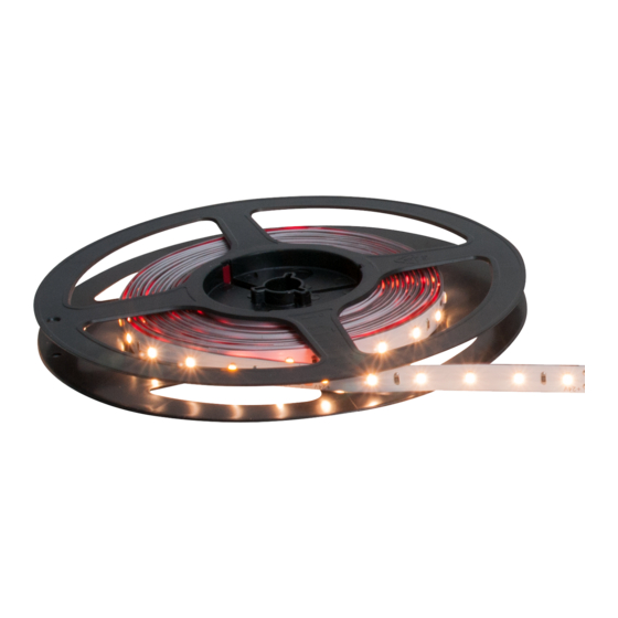
- Page 1 Flex Eco Interior User guide...
-
Page 3: Table Of Contents
CONTEN TS IN TR OD UC T ION ........2 Welcome Channel types IN STA L L ATIO N ......... . 4 Cleaning and preparing the mounting surface Cutting and connecting the tape Powering and dimming Flex Eco tapes Flex 45 degree channel (FLX 45D) -
Page 4: Int Rodu C T Ion
INT RODU C T ION W E LCO M E Welcome to the Flex Eco Interior range from Acclaim Lighting. These ultra low power LED tapes, together with a wide range of mounting channels (see opposite page), suit many installation situations. -
Page 5: Channel Types
CHANNEL T YPE S Flex pendant channel [FLK PEN] Flex 45 degree channel [FLX 45D] A neatly rounded channel, A low profile channel which designed to be suspended holds the Flex Eco tape by wires or rods - with at 45 degrees to the the option of power mounting surface. -
Page 6: Insta Ll At Ion
INSTA LL AT ION Flex Eco Interior tapes are supplied with 3M™ VHB acrylic adhesive backing, protected by a peel-off paper liner. To ensure that good adhesion is achieved, ensure the mounting surface is free of grease, moisture and any contaminates. WH E N MO UN T I NG O N TH E SIDES O R U N DE R SID E S OF SU R FAC E S Sealant We recommend that you add small dots of silicone sealant along both... -
Page 7: Cutting And Connecting The Tape
CUTTI NG AN D CO NN E C TING T HE TAPE Flex Eco tapes are supplied with a fixed 3.28’ (1m) feed cable (with bare tails). TO CUT THE TAPE Flex Eco tapes are marked with a cut line every four inches (102mm) - every six LED emitters. IMPORTANT: Do not cut the tape at any location other than the cut line. -
Page 8: Powering And Dimming Flex Eco Tapes
POWERING AN D DIM M ING F L E X E CO TA PES Flex Eco tapes are run at 24VDC and consume power as follows: per foot per meter per 16.4’ (5m) spool • 0.97W 3.2W Note: The maximum overall tape length per run is 16.4’ (5 meters). This is limited by the current capacity of the power buses within each tape. - Page 9 APS- 240- 24 This DIN-rail 240W power supply can power up to twelve 16.4’ (5 meter) Flex Eco spools. It could also be used in conjunction with one or more AL Driver 1 units to provide power for dimming operations. APS-240-24 power supply unit...
- Page 10 APS-300 -24-IP This IP67 rated power supply can power up to sixteen 16.4’ (5 meter) Flex Eco spools. It could also be used in conjunction with AL Driver 1 units to provide power for dimming operations. Up to sixteen 16.4’ (5 meter) Flex Eco tapes can be run (in parallel, NOT daisy chained) APS-300-24-IP...
- Page 11 This compact unit measures just 3.5” x 1.6” x 0.8” and provides dimming control for Flex Eco tapes from either analog 0-10V or digital DMX control inputs. The AL Driver 1 unit requires a 24VDC power supply (such as the Acclaim Lighting APS-240-24) and can drive up to two spools.
- Page 12 AL D RIVE R 4 00 24V This combined power supply and driver provides dimming control for multiple Flex Eco tapes from DMX/RDM, 0-10V or DALI inputs. See AWG recommendations on page 6. AL Driver 400 24V unit Black X / R Up to ten 16.4’...
-
Page 13: Flex 45 Degree Channel (Flx 45D)
F L EX 4 5 D EGRE E CH A NN E L (F LX 45D) This low profile channel holds the Flex Eco tape at 45 degrees to the mounting surface. The channel can be wall or ceiling mounted. Clear, opal and frosted lens options are available. For channel dimensions, see page 33. - Page 14 TO SU RFACE MO U NT Solder the link 1 Fit the Flex Eco tape to the channel (see Page cables to the 11). contact pads 2 At the end where the connection will take place, fit an End cap with hole. 3 Feed the link cables through the end cap and carefully solder to the contact pads, if necessary (see page 5).
-
Page 15: Flex Pendant Channel (Flk Pen)
F LEX PENDANT C H AN N E L (F LK PE N) The Flex pendant channel can be mounted from fixed steel rods, stainless wire or against a flat surface. Conductive end caps or fasteners can be used to transfer power via the supportive wires or rods. - Page 16 TO SU RFACE MO U NT Solder the link 1 Fit the Flex Eco tape to the channel (see page cables to the 13). contact pads 2 At the end where the connection will take place, fit an End cap with hole. 3 Feed the link cables through the end cap and carefully solder to the contact pads, if necessary (see page 5).
- Page 17 TO S US PEN D USING CONDU C TIVE FASTENERS 1 Fit the Flex Eco tape to the channel (see page 13). 2 At each end, fit an End cap with hole. 3 At each end, feed a link cable through the end cap and carefully solder to the contact pad (see page 5).
- Page 18 TO FIT A LEN S 1 Measure the exact length of lens required between the end caps at each end of the channel. 2 Carefully cut the lens to length. Ensure that any Lens resulting burrs are removed. recess 3 Insert one end of the lens against one of the end caps so that it locates into the ‘Lens recess’...
-
Page 19: Flex Graze Channel (Flk Grz)
F L EX GR A Z E CHA N N E L (F LK GRZ ) The Flex graze channel is a low profile channel that, when used with its rounded lens produces a linear spread of light suitable for grazing nearby surfaces. The supplied mounting rail can be optionally used to alter the distance between the emitters and the lens and thus determine the resulting beam angle (the beam angle is 10 as standard if the... - Page 20 TO SU RFACE MOUNT Solder the link 1 Fit the Flex Eco tape to the channel (see page cables to the 17). contact pads 2 Determine the size of hole required to pass the Flex Eco tape connection wires and drill a hole through one of the End caps.
-
Page 21: Flex Mini Channel (Flx Min)
F LEX M INI CH A N N E L ( F LX M IN ) The Flex mini channel is a very low profile channel with minimal standoff from the mounting surface. A choice of three lenses provide varying light distributions while mounting is best handled using the steel mounting bracket options. - Page 22 TO MO U N T THE CHAN NEL 1 Fit the Flex Eco tape to the channel (see page 19). 2 At the end where the connection will take place, fit an End cap with hole. If necessary, solder 3 Feed the link cables through the end cap the link cables to and carefully solder to the contact pads, if the contact pads...
-
Page 23: Flex Mini Square Channel (Flx Msp)
F L EX M IN I S Q UA RE C HA NNE L (FL X MS P) The Flex mini square channel is a low profile channel with a square overall cross section. A choice of three lenses provide varying light distributions while mounting is best achieved using the steel mounting bracket options. - Page 24 TO MOU NT T H E C HA NNEL 1 Fit the Flex Eco tape to the channel (see page 19). 2 At the end where the connection will take place, fit an End cap with hole. 3 Feed the link cables through the end cap and carefully solder to the contact pads, if necessary (see page 5).
-
Page 25: Flex Channel - Low Profile (Flx444)
F LEX C HANNE L - LOW P RO F I LE (FLX 444) This low profile option is ideal for mounting within tight spaces. There is a choice of clear, frosted or opal lenses. For channel dimensions, see page 33. Options Angled brackets plus... - Page 26 TO SU RFACE MO U NT DI RE C T LY 1 Before fitting the Flex Eco tape, determine where Drill countersunk holes and the channel is to be mounted. use screws that will lie flush with the channel base 2 Drill the required number of holes in the base of the channel and countersink them.
-
Page 27: Flex Channel - Recessed/Tall (Flx777/888)
F LEX C HANNE L - R E C E SSE D/ TALL (FLX777/88 8) These two options suit varying installation requirements: A recessed channel for concealment within surfaces and a tall profile channel that reduces light spill. These two channels have a choice of clear, frosted or opal lenses. - Page 28 TO SU RFACE MOUNT DIRE C TLY 1 Before fitting the Flex Eco tape, determine where Drill countersunk holes and the channel is to be mounted. use screws that will lie flush with the 2 Drill the required number of holes in the base of channel base the channel and countersink them.
- Page 29 TO FI T A L EN S 1 Measure the exact length of lens required between each end of the channel. 2 Carefully cut the lens to length. Ensure that any resulting burrs are removed. 3 Depending on the channel type: Lens •...
-
Page 30: Flex Drywall Channel (Flk Dwm/Dwc/Dwf)
FLE X DRYWAL L CHA NN E L (F L K DWM/ DWC/DWF) An adaptable system of channels for use with drywall installations. The main FLK DWM mount can be pre-installed during first fix while a choice of two inner channels (containing the Flex Eco tape plus connections) can be added later. - Page 31 TO FIT THE FLE X ECO TAP E 1 If necessary, cut the channel to the length required. Ensure that any resulting burrs are removed. 2 Ensure the tape mounting surface within the channel is completely dry, clean and free of grease.
- Page 32 2 If necessary, carefully solder to the contact pads or use a feed/ link cable (see page 5). Note: If you need to fit Channel end caps, you will need to drill a hole in the end cap at one end to allow the cables to pass thru. 3 Fit the Flex Eco tape to the channel (see page 29).
- Page 33 TO S U RFAC E MOUN T A CHAN NEL ON A D RYWALL C EI LIN G 1 If necessary, carefully solder to the contact pads or use a feed/link cable (see page 5). Note: If you need to fit Channel end caps, you will need to drill a hole in the end cap at one end to allow the cables to pass thru.
- Page 34 TO FIT A LEN S 1 Measure the exact length of lens required between the ends of the channel. Lens 2 Carefully cut the lens to length. Ensure that any recess resulting burrs are removed. 3 Insert one end of the lens so that it locates into the ‘Lens recess’...
-
Page 35: F Ur Th Er Infor Mat Ion
F UR TH ER INFOR MAT ION CHANNEL DI ME N SIO N S All channels and lenses are supplied in lengths of 3.28’ (1m) except for FLX444, FLX777 and FLX888 (and their respective lenses) which are all supplied in lengths of 4’ (1.21mm). FL EX 45 DEGREE F LEX MI NI F LEX M I NI... - Page 36 FLEX DRYWALL CHANNE L Mount [FLK DWM] Channel Channel [FLK DWC] with flange [FLK DWF] www.acclaimlighting.com...
-
Page 37: Flex Eco Interior Specifications
F LEX ECO INT ER IO R S PE C I F IC AT IO NS Beam angle Color temperature (CCT) 2400K, 2700K, 3000K, 3500K or 4000K Lumens 106 @ 4000K (1’ section) Efficacy (lm/W) 105 @ 4000K Color Rendering Index (CRI) >80 @ 4000K Lumen maintenance (L 50,000 hours (25... -
Page 38: Mounting Surface Advice
MOUNTING S UR FACE A DV IC E The 3M™ VHB adhesive applied to the back of Flex Eco tapes provides adhesion to a wide variety of surfaces. Advice for the preparation of certain surfaces is given below. WOO D, PARTICLE BOA R D AND CEMENT S URFAC ES Rough, porous or fibered materials such as wood, particleboard, cement, etc., have an open surface and require sealing to provide a unified surface for tape bonding. -
Page 39: Limited Product Warranty
If the requested repairs or service (including parts replacement) are within the terms of this warranty, Acclaim Lighting will pay return shipping charges only to a designated point within the United States. If the entire instrument is sent, it must be shipped in its original package. - Page 40 www.acclaimlighting.com...
Need help?
Do you have a question about the Flex Eco Interior Series and is the answer not in the manual?
Questions and answers