Advertisement
Quick Links
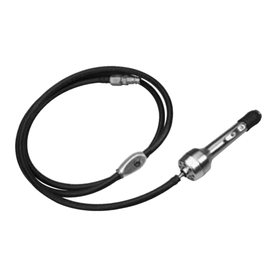
Disassembly/Assembly Instructions - Quick-Change Pencil Grinder, Drive & Motor
Models: 60051, 60052
Important: Use these instructions along with tool parts page or manual.
Notice: Shut off air supply. Open 51655 ON/OFF Valve to deplete air.
Disconnect hose from air supply.
Drive/Motor Disassembly:
Assembly Instructions - Quick-Change Pencil Grinder
Header
1. xxxxxx
Rotate 60083 Lever 90° to open collet.
1.
Remove insert tool from collet. Notice: If necessary, use 60116 wrench.
Turn counterclockwise.
Advertisement

Related Manuals for Dynabrade 60051


Summary of Contents for Dynabrade 60051
- Page 1 Disassembly/Assembly Instructions - Quick-Change Pencil Grinder, Drive & Motor Models: 60051, 60052 Important: Use these instructions along with tool parts page or manual. Notice: Shut off air supply. Open 51655 ON/OFF Valve to deplete air. Disconnect hose from air supply.
- Page 2 Remove collet insert from drive shaft. Turn conterclockwise.
- Page 3 Use a piece of rubber to protect housing and fasten in vise with aluminum or bronze jaws. Use an adjustable wrench to remove 60066 Nose Cone. Turn counterclockwise.
- Page 4 60081 Washer 60094 Spring 60087 Washer Seal Carefully, remove 60081 Washer, 60094 Spring and 60087 Washer Seal.
- Page 5 HEAT Invert tool in vise. Use a HEAT GUN to warm housing and soften thread sealant.
- Page 6 Use an adjustable pin spanner wrench to remove 60110 or 60111 Cover. Turn counterclockwise. Set cover, brake and hose assemblies aside. See: Disassembly/Assembly Instructions - Quick-Change Pencil Grinder, Bushing & Brake, to replace air bushing and/or brake.
- Page 7 Remove from vise. NOTICE: Quick-Change Chuck is SPRING LOADED! Use caution when removing 60077 Bumper. Use an adjustable wrench on 60077 Bumper, and insert 4 mm hex key into end of drive shaft. Carefully, turn bumper counterclockwise to remove from drive shaft.
- Page 8 Use a 1/4" (6 mm) Ø diameter by ~5" (~127 mm) long screw and carefully slide, 60088 Front Seal Washer, 60089 Outer Housing Seal, 60090 Inner Race Seal, 60092 Rear Seal Washer, 60093 Bearing, 60074 End Support and 60073 Springs (19 to 20) onto screw.
- Page 9 Use a HEAT GUN to warm lever and soften Loctite #271. Use 2 mm hex key to remove 60112 Set Screw. Turn counterclockwise.
- Page 10 60113 Pin Wrench 10. Fasten in vise and use 60113 Pin Wrench to remove 60080 Cam Support. Turn counterclockwise.
- Page 11 11. Remove 60080 Cam Support and 60082 Cam.
- Page 12 12. Remove drive shaft, turbine motor, 51651 Bearing and 60102 Spring from housing.
- Page 13 PRESS FIT ! 13. Fasten drive shaft in vise. Identify PRESS-FIT hole in 60078 Spring Washer. (NO CHAMFER) Use ~1/16" or ~1.5 mm Ø drive punch to remove the 60091 Pin. Remove 60078 Spring Washer and 60079 Screw.
- Page 14 14. Reposition drive shaft in vise and use 4 mm hex key to hold it stationary. Use an adjustable wrench to remove 60099 Nut. Turn counterclockwise.
- Page 15 15. Remove 60069 Top Brake Plate and 51378 Turbine.
- Page 16 16. Use ~1/16" or ~1.5 mm Ø drive punch to remove the 60098 Pin. Remove 51675 or 51691 Governor and 51656 Turbine Base. Drive/Motor Disassembly Completed. Clean and inspect parts for wear or damage before assembling.
- Page 17 Drive/Motor Assembly: VISE 51651 Bearing 60079 Screw 60078 Spring Washer 60102 Spring Install 60102 Spring and 51651 Bearing onto 60117 Drive Shaft. Install 60079 Screw in alignment with slot in drive shaft. Notice: Identify SLIP-FIT HOLE in 60078 Spring Washer. With larger diameter toward collet body end of drive shaft install spring washer with SLIP-FIT HOLE up.
- Page 18 Fasten drive shaft in vise with ‘Motor End’ pointing up. Install 51656 Turbine Base onto drive shaft. Install 60098 Pin through ‘Cross-Hole’ so that it is ‘Centered’ in drive shaft.
- Page 19 GOVERNOR TURBINE Install 51678 Turbine and 51675 or 51691 Governor (stretch governor around pin).
- Page 20 Loctite #222 Install 60069 Brake Plate. Align, ‘slot & notch’ brake plate features, with 60089 Pin, and 51678 Turbine. Apply a small amount of Loctite #222 or equivalent to threads on drive shaft.
- Page 21 Torque to 4.5 N•m/~40 lbs. in. 5. Use 1/2" hex socket and torque wrench to install 60099 Nut. Torque to 4.5 N•m/~40 lbs. in.
- Page 22 6. Carefully transfer 60073 Springs, and 60074 End Support onto drive shaft.
- Page 23 Use 60077 Bumper to temporarily retain parts.
- Page 24 Loctite #609 Apply a small amount of Loctite #609 to outside diameter of 51651 Bearing.
- Page 25 Install assembly.
- Page 26 96418 Bearing Press Tool 10. Remove 60077 Bumper. Back-Up 60099 Nut with 96418 Bearing Press Tool. Install 60093 Bearing, 60092 Rear Seal, 60090 Inner Race Seal, 60089 Outer Housing Seal and 60088 Front Seal. Reinstall 60077 Bumper. Notice: Push against bumper to compress spring washers while turning bumper to catch threads and retain parts.
- Page 27 4 mm 11. Use a 4 mm hex key and, an adjustable wrench to fasten 60077 bumper.
- Page 28 Loctite Primer #7649 12. Apply Loctite Primer #7649 or equivalent to threads of 60110 or 60111 Cover.
- Page 29 Loctite #567 13. Wait five minutes, and then apply a small amount of Loctite #567 or equivalent.
- Page 30 Torque to 14N•m/~125 lbs. in. 14. Fasten turbine cover on housing. Torque to 14N•m/~125 lbs. in.
- Page 31 Place into 60060 Nose Cone. 60081 Washer 60094 Spring 60087 Washer Seal Loctite #567 15. Install 60081 Washer, 60094 Spring, and 60087 Washer Seal into 60060 Nose Cone. Apply a small amount of Loctite #567 or equivalent to threads on housing.
- Page 32 14 mm Torque to 4.5 N•m/~40 lbs. in. 16. Install 60066 Nose Cone. Use a 14 mm crowfoot and torque wrench to fasten. Torque to 4.5 N•m/~40 lbs. in.
- Page 33 Loctite #271 Point Set Screw Pocket Forward 17. Insert 60082 Cam through 60080 Cam Support. Notice: Point ‘SET SCREW POCKET’ forward. Apply a small amount of Loctite #271 to threads of cam support.
- Page 34 60113 Pin Wrench 18. Use 60113 Pin Wrench to fasten 60080 Cam Support.
- Page 35 Loctite #271 19. Apply a small amount of Loctite #271 to 60112 Set Screw...
- Page 36 20. Use 2 mm hex key to tighten 60112 Set Screw. Fasten 60083 Lever in line with housing.
- Page 37 90° 21. Rotate 60083 Lever 90° to compress spring washers and open collet. Install 60118 or 60119 Collet Insert in drive shaft collet body.
- Page 38 90° 22. Use 94600 (1/8") or 94601 (3/32") Ø Pin to guage correct adjustment and fit of collet inserts With 60083 Lever turned 90° to housing, insert guage pin. Check fit by inserting and removing pin. The pin should slide in and out of collet without resistance while still having a close fit.
- Page 39 23. With collet fit adjusted. Rotate 60083 Lever into alignment with housing. Collet will close tight on guage pin. Drive/Motor Assembly Completed. Use tool parts page or manual to identify valve, brake and exhaust components and the order of assembly. Important: Allow Loctite Threadlockers and Retaining Compounds to cure/fixture for 30 minutes before checking RPM.
Need help?
Do you have a question about the 60051 and is the answer not in the manual?
Questions and answers