Table of Contents
Advertisement
Quick Links
Advertisement
Table of Contents

Related Manuals for TP-Link Omada SG2428LP


Summary of Contents for TP-Link Omada SG2428LP
- Page 1 Business Networking Solution Installation Guide Omada Smart Switch...
- Page 2 Remind to take notice. The note contains the helpful information for a better use of the product. Related Document The User Guide and CLI Reference Guide of the product are provided on Download Center. To obtain the latest product information, visit the official website: https://www.tp-link.com/ support/download/?type=smb.
-
Page 3: Table Of Contents
Contents Chapter 1 Introduction ——————————— 01 Product Overview ............01 Appearance ...............01 Chapter 2 Installation ——————————— 05 Package Contents ............05 Safety Precautions ............05 Installation Tools ..............07 Product Installation ............07 Chapter 3 Connection ——————————— 09 Ethernet Port ..............09 SFP Slot ................09 Verify Installation .............09 Power On ................10 Initialization ................10 Chapter 4 Configuration ——————————... -
Page 4: Introduction
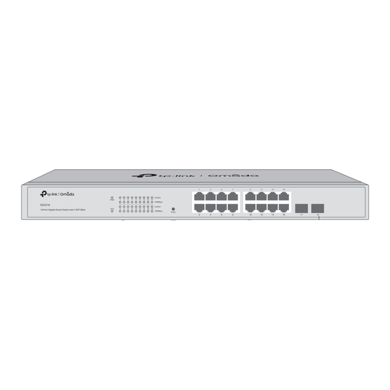
QoS and IGMP snooping/filtering optimize voice and video application. Link aggregation increases aggregated bandwidth, optimizing the transport of business critical data. SNMP, RMON, WEB and CLI Login bring abundant management policies. TP-Link Omada Smart Switch integrates multiple functions with excellent performance, and is friendly to manage, which can fully meet the need of the users demanding higher networking performance. - Page 5 Omada Smart Switch The front panel of SG2218P is shown as the following figure. Figure 1-3 Front Panel of SG2218P LEDs Reset 10/100/1000 Mbps RJ45 Port SFP Slot The front panel of SG2428LP is shown as the following figure. Figure 1-4 Front Panel of SG2428LP LEDs LED Mode...
- Page 6 Omada Smart Switch LEDs For SG2218 Indication On: The switch is powered on. Off: The switch is powered off or power supply is abnormal. Flashing: Power supply is abnormal. Flashing: The switch works properly. On or Off: The switch works improperly. On: A device is connected to the corresponding port but no activity.
- Page 7 Omada Smart Switch Indication Green On: The port is supplying power normally. Green Flashing: The supply power exceeds the correponding port's maximum power. 10/100M or PoE Yellow On: Overload or short circuit is detected. Speed or PoE Yellow Flashing: Power-on self-test failed. (When the PoE LED Off: Not providing PoE power on the port.
- Page 8 PE (Protecting Earth) cable of AC cord or with Ground Cable. For detailed lightning protection measures, go to https://www.tp-link.com/support/download/?type=smb, search the model number of your switch and go to the product Support web page, refer to the Lightning Protection Guide from the Related Documents: https://www.tp-link.com/us/configuration-guides/lightning_protection_guide/.
-
Page 9: Chapter 2 Installation
Omada Smart Switch Chapter 2 Installation Package Contents Make sure that the package contains the following items. If any of the listed items is damaged or missing, please contact your distributor. One Power Cord One Switch Mounting brackets, screws and Installation Guide rubber feet *Images are for demonstration only. - Page 10 Omada Smart Switch Keep the equipment room at an appropriate level of temperature and humidity. Too much or too little humidity may lead to bad insulation, leakage of electricity, mechanical property changes, and corrosion. High temperatures may accelerate aging of the insulation materials, significantly shortening the service life of the device.
-
Page 11: Installation Tools
Use the signal SPD (Surge Protective Device) when wiring outdoor. ■ Note: For detailed lightning protection measures, refer to the Lightning Protection Guide: https://www.tp-link.com/us/configuration-guides/lightning_protection_guide/. Installation Site When installing the device on a rack or a flat workbench, attach much importance to the following items: The rack or workbench is flat, stable, and sturdy enough to support the weight of 5.5 kg at least. - Page 12 Omada Smart Switch Figure 2-1 Desktop Installation Feet Bottom of the Device Notch Rack Installation ■ To install the device in an EIA standard-sized, 19-inch rack, follow the instructions described below: 1. Check the efficiency of the grounding system and the stability of the rack. 2.
-
Page 13: Chapter 3 Connection
Omada Smart Switch Chapter 3 Connection Ethernet Port Connect an Ethernet port of the switch to the computer by RJ45 cable as the following figure shows. Figure 3-1 Connecting the RJ45 Port RJ45 Port RJ45 Cable SFP Slot The following figure demonstrates the connection of SFP module to an SFP slot. Figure 3-2 Inserting the SFP Module SFP Slot... -
Page 14: Power On
Omada Smart Switch Power On Plug the negative connector of the provided power cord into the power socket of the device and plug the positive connector into a power outlet as the following figure shows. Figure 3-3 Connecting to Power Supply Note: The figure is to illustrate the application and principle. -
Page 15: Chapter 4 Configuration
3. After a successful login, the main page will appear. You can click the menus on the top side and left side to configure the corresponding functions. For the detailed configurations, refer to the User Guide and CLI Guide. The guides can be found on the download center of our official website: https://www.tp-link.com/support/download/?type=smb. Using the CLI ■... -
Page 16: Controller Mode
Omada Smart Switch Controller Mode Controller Mode applies to the large scale network with mass devices. All devices can be centrally configured and monitored via Omada Hardware Controller or Omada Sof t ware Controller. Note: Before the following configurations, make sure the switch can access the internet. When using Omada Software/Hardware Controller, make sure the switch and the controller are in the same subnet. - Page 17 Make sure that Cloud Access is enabled on your controller and your controller has been bound with your TP-Link ID. On the Omada Controller’s web page, go to Settings > Cloud Access to enable Cloud Access and bind your TP-Link ID. If you have set it up in the quick setup, skip this step.
-
Page 18: Appendix A Troubleshooting
Omada Smart Switch Appendix A Troubleshooting Q1. What could I do if I forgot the username and password of the switch? Press the Reset button for at least 5 seconds to reset the system. The system will be reset to the factory default settings, and the default login user name and password are both admin. -
Page 19: Appendix B Specifications
Appendix B Specifications Item Content IEEE 802.3i, IEEE 802.3u, IEEE 802.3ab, IEEE 802.3ad, IEEE 802.3z, IEEE 802.3x, IEEE 802.1p, IEEE 802.1q, IEEE 802.1x, IEEE 802.1d, IEEE 802.1s, IEEE 802.1w Standards IEEE 802.3af, IEEE 802.3at (For SG2210MP/SG2218P/SG2428LP/SG2428P/ SL2428P) 10Base-T: UTP/STP of Cat. 3 or above 100Base-TX: UTP/STP of Cat. - Page 20 EU declaration of conformity TP-Link hereby declares that the device is in compliance with the essential requirements and other relevant provisions of directives 2014/30/EU, 2014/35/EU, 2011/65/EU and (EU)2015/863. The original EU declaration of conformity may be found at https://www.tp-link.com/en/support/ce/...
Need help?
Do you have a question about the Omada SG2428LP and is the answer not in the manual?
Questions and answers