Table of Contents
Advertisement
Quick Links
Advertisement
Table of Contents

Subscribe to Our Youtube Channel
Related Manuals for Tatu Marchesan GNF


Summary of Contents for Tatu Marchesan GNF
- Page 1 I N S T R U C T I O N S M A N U A L...
- Page 2 IDENTIFICATION Dealer: Owner: Firm / Farm: City: State: No. of the Certificate of Guarantee: Serial / No.: Date: Invoice No.: Product: Notes:...
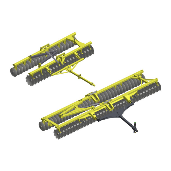
- Page 3 GNF model also features a central articulation in the chassis with ideal buoyancy to follow the surface unevenness or even to perform the finishing on broad-based terraces. The GNF disk harrow is supplied with 36 - 72 disc blades that normally operate by the traction bar. This...
-
Page 4: Table Of Contents
Table of contents 1. To the owner 2. To the operator 4 to 8 3. Technical specifications 4. Components 10 & 11 5. Assembly 12 to 21 Using the set of wrenches Assembly of bearings and spacer spools 12 to 14 Disc gangs assembly 15 &... -
Page 5: To The Owner
To the owner The acquisition of any TATU product assures to the original purchaser the following rights: • Warranty certificate; • Instructions manual; • Technical assistance by the dealer on equipment delivery. However, the owner must check the condition of the equipment on delivery, as well as knowing the warranty terms. -
Page 6: To The Operator
The GNF disk harrow is simple to operate, requiring however the basic and essential cautions to its handling. Always keep in mind that safety requires constant attention, observation and prudence during the harrowing, transportation, maintenance and storage. - Page 7 To the operator Never use your bare hands to check hydraulic leaks, the high pressure can cause several injuries. Never attempt to change the adjustments, clean or lubricate the equipment when the same is switched on or in movement. Be careful while driving on slopes. Risk of overturn. Prevent that chemical products (i.e.: fertilizers, treated seeds) make any contact with your skin or clothes.
- Page 8 To the operator • Only trained and qualified personnel is allowed to operate the equipment. • While working or during transportation, only the presence of the operator is allowed on the tractor. • Do not allow children to play near or over the equipment while it is operating, during transportation or storage.
- Page 9 To the operator Truck or trailer transportation Marchesan does not advise the equipment traffic on highways, because this practice involves serious security risks in addition to being prohibited by the current existing traffic law. The transportation for long distances should be done on truck, trailer or others by following these safety guidelines: •...
- Page 10 To the operator Safety stickers The safety stickers warn about the equipment points that require more attention and they should be kept in good repair. If these stickers become damaged or illegible, replace them. Marchesan provide stickers, upon request and indication of the respective serial number.
-
Page 11: Technical Specifications
Technical specifications Type: ..........Hinge Wheel Type Offset Leveling Floating Harrow Model: .........................GNF Spacing between disc blades: ................ 195 mm Disc blades dimension: ............... Ø 18" x 3,0 mm ................ Ø 20" x 3,5 mm Number of disc blades: ......... 36, 40, 44, 48, 52, 56, 60, 64, 68 and 72 Disc blade type: .......... -
Page 12: Components
Components GNF (36 to 60 disc blades) 01 - Front chassis 02 - Rear chassis 03 - Opening adjustment set 04 - Stabilizer bars 05 - Front disc gang 06 - Rear disc gang 07 - Articulation lock 08 - Traction unit 09 - Tractor hitch Optional parts: Page 28. - Page 13 Components GNF (64 to 72 disc blades) 01 - Front chassis 02 - Rear chassis 03 - Hydraulic cylinder 04 - Stabilizer bars 05 - Front disc gang 06 - Rear disc gang 07 - Articulation lock 08 - Traction unit 09 - Tractor hitch Marchesan Implementos e Máquinas Agrícolas “TATU”...
-
Page 14: Assembly
Assembly First of all, put the parts in a clean place to identify them easier. Check the parts using the list that comes inside the packing box. Using the set of wrenches • Use two box wrenches (A) to tighten the nuts of the disc gangs, one to hold the axis nut on one side while the other tight the nut to the other end, thereby preventing the axis from rotating. - Page 15 Assembly Assembly of bearings and spacer spools GNF - 36 GNF - 40 GNF - 44 GNF - 48 GNF - 52 GNF - 56 Marchesan Implementos e Máquinas Agrícolas “TATU” S.A.
- Page 16 Assembly Assembly of bearings and spacer spools GNF - 60 GNF - 64 GNF - 68 Bearing GNF - 72 Spacer spool Furrow filler Marchesan Implementos e Máquinas Agrícolas “TATU” S.A.
-
Page 17: Disc Gangs Assembly
Assembly Disc gangs assembly • Place the external lock (A) along with the axis (B). • Tighten the nut (C) passing 5 mm from the axis face. • Place a disc blade (D) and a bearing (E), paying attention to the furrow fillers in the rear ends of the harrow. - Page 18 Assembly Torque table Axis diameter Ft. - lbs. 1.1/2" 1600 1.5/8" 1900 2.1/8" 2100 2.1/2" 2300 Consult torque table on page NOTE Marchesan Implementos e Máquinas Agrícolas “TATU” S.A.
-
Page 19: Assembly Of Disc Gangs On The Chassis
Assembly Assembly of disc gangs on the chassis The rear gang turns dirt to the left and the front gang turns dirt to IMPORTANT the right. • In the gang assembly to the carriers, the bearing hangers should remain facing the disc blades concavity. •... - Page 20 Assembly Chassis junction • Approach both chassis (A and B) and place the junction pin (C) along with a flat washer, castle nut and cotter pin. Scrapers assembly • Note the fixing point of the scrapers with the end facing the concave side of the disc blades.
-
Page 21: Opening Adjustment Set Assembly
Assembly Opening adjustment set assembly • Couple the front (A) and rear (B) stabilizer bar to the respective chassis, using the junction pin (C) and cotter pins. • Fasten the course limiter (D) to the support (E) using a cotter pin. •... -
Page 22: Traction Unit Assembly
Assembly Traction unit assembly • Couple the hitch bar (A) to the front chassis using reels (B), pins (C) and cotter pins. • Then, assemble the traction bar (D) using a pin (E), cotter pin and bolt. Observe the correct position of the upper and lower plates, which are NOTE assembled according to the illustrations below. -
Page 23: Hydraulic Cylinder To Open Or Close The Gangs
• The rod stops come along with the cylinder and they must be assembled in the cylinder rod. • If the GNF has 64 - 72 disc blades, the cylinder must be coupled to the bar (A) and to the front chassis. -
Page 24: Working Preparation
Working preparation The following instructions must be carefully observed in order to get the best work performance. Tractor preparation The addition of ballast water in the tires and a set of weights on the front part and rear wheels of the tractor are the most used ways to increase the soil traction and give greater stability to the tractor. -
Page 25: Adjustments And Operations
Adjustments and operations Cutting depth adjustment The cutting depth is adjusted by the following points: 1) Disc gangs opening. • Increase the (A) opening between the gangs to work in soils with greater difficult to penetrate the disc blades. In light and loose soils, it is appropriate to work with a smaller opening angle. - Page 26 Adjustments and operations 2) Traction bar angle. • In medium soils, the traction bar works in the central hole of the upper and lower plates. • Use the first hole (A) to get the smallest disc blades penetration angle. Displace the bar to the other holes in order to increase the penetration angle.
-
Page 27: Ways To Start The Harrowing
Adjustments and operations Ways to start the harrowing Regardless of the format and size of the field, the harrowing is made basically in two ways: from outside to inside or from inside to outside. Entrance Entrance Harrowing in squares Harrowing in squares from outside to inside from inside to outside Harrowing in level... -
Page 28: Direction Of The Maneuvers
Adjustments and operations Direction of the maneuvers As described in the foregoing adjustments, the GNF disk harrow provides various working angles to operate properly in all types of soil. However, these harrows require certain care during operations, like never make maneuvers to the right, because the angle formed by the "V"... -
Page 29: Operations - Important Points
Use cardboard or other suitable object. • Relieve the control valve pressure before disconnecting the quick couplers. • As previously mentioned the GNF harrow has several settings. However, only the local conditions can determine the best adjusment thereof. -
Page 30: Optional
Hydraulic cylinder to open or close the gangs Optionally, Marchesan supplies an hydraulic cylinder to assist the harrow, performing the movements to open or close the disc gangs. (See how to assemble the cylinder on page 21). GNF (36 to 52 discs) GNF (56 to 60 discs) -
Page 31: Maintenance
Maintenance Lubrication The simplest way to extend the lifetime of your harrow and avoid interruptions during work is to lubricate it properly, as indicated below. 1) Every 24 hours of service, lubricate the articulations through the grease fittings in the following way: •... -
Page 32: Lubrication Points
Maintenance Lubrication points Lubricate every 24 operating hours. Marchesan Implementos e Máquinas Agrícolas “TATU” S.A. - Page 33 Maintenance Harrow maintenance • In disuse period wash the harrow, repair the paint failure, protect the discs with oil, lubricate all grease fittings and store the harrow in a covered and dry location, avoiding contact with the soil. • The disc blades should be replaced as soon as you notice a low-income thereof, characterized mainly by the reduction in diameter, cut loss and other damages to which they are subjected during work.
-
Page 34: Important Data
Important data Calculation of hourly income To calculate the hourly income of the GNF disk harrow, use the following calculation: R = L x V x E Where: R = Hourly income; L = Harrow working width (in meters); V = Average speed of the tractor (in meters per hour);... -
Page 35: Average Income Table
To know how many hours will be spent to work a certain previously known area, it is necessary to divide the value of the area by the hourly income. Example: An area of 50 hectares to be worked with a GNF of 48 disc blades (Hourly income = 3,63 ha). -
Page 36: Torque Table
Important data Torque table TORQUE VALUES CHART Grade 2 Grade 5 Grade 8 Bolt Diameter Coarse Fine Coarse Fine Coarse Fine 1/4” 50 In. Lbs. 56 In. Lbs. 76 In. Lbs. 87 In. Lbs. 9 Ft. Lbs. 10 Ft. Lbs. 5/16”... -
Page 37: Important
Important MARCHESAN S/A reserves the right at any time to make improvements ATTENTION in the design, material or specifications of machinery, equipment or parts without thereby becoming liable to make similar changes in machinery, equipment or parts previously sold. Images are for illustration purposes only. Some illustrations in this manual appear without the safety devices, removed to allow a better view and detailed instructions. -
Page 38: Notes
Notes Marchesan Implementos e Máquinas Agrícolas “TATU” S.A.
Need help?
Do you have a question about the GNF and is the answer not in the manual?
Questions and answers