
Subscribe to Our Youtube Channel
Related Manuals for Tatu Marchesan GAT 800


Summary of Contents for Tatu Marchesan GAT 800
- Page 1 GAT 800 / GAT 1000 GAT 800 / GAT 1000 GATR / GATG GATR / GATG GATG-RO / GATG-LD GATG-RO / GATG-LD GATG-BR 2.0T GATG-BR 2.0T OPERATOR’S MANUAL...
- Page 2 IDENTIFICATION Dealer: Owner: Firm / Farm: City: State: No. of the Certificate of Guarantee: Serial / No.: Date: Invoice No.: Product: Notes:...
- Page 3 Introduction This operator's manual helps on the assembly process and provides the necessary information for the correct operation and maintenance, thus assuring a higher yield, safety and durability. This manual contains the necessary information for the best performance of your equipment. The operator and the maintenance staff must carefully read the entire manual before working with the equipment.
-
Page 4: Table Of Contents
04 to 13 3. Data sheet 14 to 17 4. Components 18 to 24 5. Assembly 25 to 43 GAT 800 assembly GAT 1000 assembly GATR assembly GATG assembly GATG-RO assembly 29 & 30 GATG-BR 2.0T assembly 31 & 32... -
Page 5: To The Owner
1. To the owner The acquisition of any Tatu product assures to the original purchaser the following rights: - Warranty certificate; - Operator's manual; - Technical assistance by the dealer on equipment delivery. However, the owner must check the condition of the equipment on delivery, as well as knowing the warranty terms. -
Page 6: To The Operator
2. To the operator Be careful with the environment Dear operator! Respect the ecology. Do not throw trash away. This gesture of goodwill helps to protect our environment. Products such as oil, fuel, filters, batteries and others are spilt over the soil and can penetrate to the underground layers, compromising nature. - Page 7 2. To the operator Working safely Never use your bare hands to check hydraulic leaks, the high pressure can cause injuries. Never attempt to change the adjustments, clean or lubricate the equipment when the same is switched on or in movement. Be careful while driving on slopes.
- Page 8 2. To the operator Working safely Have extreme caution when operating with the power take-off (PTO), which you should not get closer during operation. The presence of any other people on the tractor or equipment is stricly forbidden. Have extreme caution when driving under electrical power lines. Any contact may result in severe shocks, injuries or death.
- Page 9 2. To the operator Personal protective equipment (PPE) The personal protective equipment must be used as stated by the Ministry of Labor The personal protective equipment must be used as stated by the Ministry of Labor and Employment on the working standards. and Employment on the working standards.
- Page 10 2. To the operator General and mandatory safety measures 1. Only trained and qualified personnel are allowed to operate the equipment. 2. While working or during transportation, only the presence of the operator is allowed on the tractor. 3. Do not allow any passengers on the equipment. 4.
- Page 11 2. To the operator General and mandatory safety measures 16. Always shut down the engine, remove the key and use the handbrake before leaving the tractor seat. 17. Never attempt to change the adjustments, clean or lubricate the equipment while it is moving. 18.
- Page 12 2. To the operator Transportation over truck or trailer Marchesan does not advise the equipment traffic on highways, because this practice involves serious security risks in addition to being prohibited by the current existing traffic law. The transportation for long distances should be done on truck, trailer or others by following these safety guidelines: 1.
- Page 13 2. To the operator Working safety standards It is important to have knowledge not only about the functioning, operation of the equipment and its technology, but also the working legal aspects when using the equipment, such as: safety standards, operator's manual and working safety. The equipment and tools used on the rural area must be properly handled, otherwise health and safety of involved personnel may be compromised.
- Page 14 2. To the operator Safety decals The safety decals warn about the equipment points that require more attention and they should be kept in good repair. If these decals become damaged or illegible, replace them. Marchesan provides decals, upon request and indication of the respective serial number.
- Page 15 05.03.03.1827 05.03.03.1822 Danger decal Hoist disengaging decal 05.03.03.1920 Grip coupler colors decal 05.03.03.4499 GAT 800 maximum load capacity decal 05.03.03.2826 GAT 1000 maximum load capacity decal 05.03.03.2827 GATR maximum load capacity decal 05.03.03.2536 05.03.03.3114 GATG, GATG-RO & GATG-BR maximum load capacity decal 05.03.03.3488...
-
Page 16: Data Sheet
3. Data sheet Intended use of the equipment The GAT 800, GAT 1000, GATR, GATG, GATG-RO, GATG-BR 2.0T and GATG-LD hoists are useful in any land to optimize the harvest of citrus fruits and to move loads. Both operation and transport are done using the three-point hitch of the tractor. - Page 17 3. Data sheet GAT 800 Type: ........................Hoist mounted type Model: ..........................GAT 800 Elevation: ........................2,300 mm Maximum load capacity: ..................... 600 kg Weight: ........................70 kg Tractor required (cv): ....................GAT 1000 Type: ........................Hoist mounted type Model: ..........................GAT 1000 Elevation: ........................3,500 mm Maximum load capacity: .....................
- Page 18 3. Data sheet GATG Type: ....................Hoist mounted type revolving Model: ...........................GATG Elevation: ........................6,250 mm Maximum load capacity: ....................2,000 kg Vertical bar height: ......................3,450 mm Width between the wheels:..................2,495 mm* Tires: ..................11L - 15 / 10 tarps (44 PSI) Weight: ..........................
- Page 19 3. Data sheet GATG - BR 2.0T Type: ............Hoist mounted type revolving adjustable wheel gauge Model: ........................GATG - BR 2.0T Elevation: ........................6,250 mm Maximum load capacity: ....................2,000 kg Vertical bar height: ......................3,450 mm Width between wheels:................2,100 and 2,990 mm* Tires: ..................
-
Page 20: Components
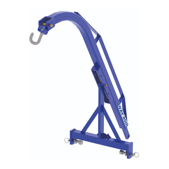
GAT 800 01 - Fixed frame 02 - Drawbar 03 - Hook 04 - Junction axle 05 - GAT 800 MF IMPORTANT - The GAT 800 MF (5) model is specific for Massey Ferguson tractors. HOISTS - Rev. 07 - Apr/22... - Page 21 4. Components GAT 1000 01 - Fixed frame 02 - Junction axle 03 - Hydraulic cylinder 04 - Chain and hook 05 - Hydraulic system 06 - Movable frame 07 - Hook HOISTS - Rev. 07 - Apr/22...
- Page 22 4. Components GATR 01 - Fixed frame 02 - Boom 03 - Hydraulic cylinder 04 - Universal joint 05 - Hydraulic system 06 - Wheels 07 - Adjustment bar 08 - Jack HOISTS - Rev. 07 - Apr/22...
- Page 23 4. Components GATG 01 - Fixed frame 02 - Boom 03 - Hydraulic cylinder 04 - Tires 05 - Jacks 06 - Universal joint 07 - Hydraulic system 08 - Adjustment bar HOISTS - Rev. 07 - Apr/22...
- Page 24 4. Components GATG-RO 01 - Fixed frame 02 - Boom 03 - Hydraulic cylinder 04 - Tires 05 - Jacks 06 - Universal joint 07 - Wheel arms 08 - Adjustment bar 09 - Hydraulic system HOISTS - Rev. 07 - Apr/22...
- Page 25 4. Components GATG-BR 2.0T 01 - Fixed frame 02 - Boom 03 - Hydraulic cylinder 04 - Tires 05 - Jacks 06 - Universal joint 07 - Wheel arms 08 - Adjustment bar 09 - Hydraulic system HOISTS - Rev. 07 - Apr/22...
- Page 26 4. Components GATG-LD 01 - Fixed frame 02 - Wheel arms 03 - Boom 04 - Boom front extension 05 - Jacks 06 - Universal joint 07 - Hydraulic cylinder 08 - Adjustment bar 09 - Tires 10 - Hydraulic system with control valve HOISTS - Rev.
-
Page 27: Assembly
2. Then, check the parts according to the list in the package. To assemble the GAT 800 and GAT 800 MF: 3. Couple the frame (A) to the drawbar (B), by placing a pin (C) and cotter pin (D) in one of the three holes of the frame, according to the height that is going to be used. -
Page 28: Gat 1000 Assembly
5. Assembly GAT 1000 assembly 1. Couple the boom (A) to the frame (B) using a junction axle (C), castle nut and cotter pin. 2. Then, fasten the hydraulic cylinder (D) using a junction axle (E) and cotter pin. 3. Couple the pressure (F) and return (G) hoses to the hydraulic cylinder (D), as shown on the 'hydraulic circuit' page. -
Page 29: Gatr Assembly
5. Assembly GATR assembly 1. Couple the boom (A) to the frame (B) using an articulation axle (C), castle nut and cotter pin. 2. Then, fasten the hydraulic cylinder (D) using an articulation axle with lock (E), bolts, flat and spring washers. 3. -
Page 30: Gatg Assembly
5. Assembly GATG assembly 1. Couple the boom (A) to the frame (B) using an articulation axle (C), flat washer, castle nut and cotter pin. 2. Fasten the hydraulic cylinder (D) using the junction axles (E) and cotter pins. 3. Right after, fasten the hydraulic cylinder (F) to the frame (B) using a fixation flange (G), bolts, spring washers and nuts;... -
Page 31: Gatg-Ro Assembly
5. Assembly GATG-RO assembly 1. Couple the boom (A) to the frame (B) using an articulation axle (C), flat washer, castle nut and cotter pin. 2. Fasten the hydraulic cylinder (D) using the junction axles (E) and cotter pin. 3. Right after, fasten the hydraulic cylinder (F) to the frame (B) using a fixation flange (G), bolts, spring washers and nuts;... - Page 32 5. Assembly GATG-RO assembly 4. Couple the wheel arm (I) to the frame (B), locking with a castle nut and cotter pin. 5. Then, assemble the hubs (J) to the wheel arm and couple the tires (K) to the hubs. 6.
-
Page 33: Gatg-Br 2.0T Assembly
5. Assembly GATG-BR 2.0T assembly 1. Couple the boom (A) to the frame (B) using an articulation axle (C), flat washer, castle nut and cotter pin. 2. Fasten the hydraulic cylinder (D) using the junction axles (E) and cotter pins. 3. - Page 34 5. Assembly GATG-BR 2.0T assembly 4. Couple the arms (I) to the frame (B) using the junction axles (J) and cotter pins. 5. Right after, fasten the wheel arms (K) to the arms and lock with castle nut and cotter pins.
-
Page 35: Gatg-Ld Assembly
5. Assembly GATG-LD assembly 1. Couple the boom (A) to the frame (B) using an articulation axle (C), flat washer, castle nut and cotter pin. 2. Fasten the boom extension (D) to the boom (A) using an articulation axle (C), flat washer, castle nut and cotter pin. - Page 36 5. Assembly GATG-LD assembly 6. Couple the arms (K) to the frame (B) using junction axles (L) and cotter pins. 7. Fasten the wheel arms (M) to the arms and lock with castle nut and cotter pins. Assemble the hubs (N) to the wheel arms and couple the tires (O) to the hubs. 8.
- Page 37 5. Assembly GATG-LD assembly 9. Assemble the hydraulic control valve (S) to the support fastened in the frame (B) using bolts, flat washers and nuts. 10. Assemble the hoses to their respective hydraulic cylinders, as shown on the 'hydraulic circuit' page. 11.
-
Page 38: Safety Valve
5. Assembly Safety valve For the For the GATG , GATG-RO, GATG - BR 2.0T and GATG-LD models: This equipment has a safety valve on its lifting cylinder that ativates when there is any This equipment has a safety valve on its lifting cylinder that ativates when there is any failure on the cylinder or on the hydraulic hoses that would stop the cylinder movement, failure on the cylinder or on the hydraulic hoses that would stop the cylinder movement, preventing that the load drops. - Page 39 5. Assembly Hydraulic circuit - GAT 1000 IMPORTANT - Always use thread sealing tape to couple the male quick coupler to the hoses. - During assembly, avoid that the ports touch the soil. - When finishing to assemble the hydraulic hoses, carry out a general inspection to check the tightening of all hose ports and if they are properly installed.
-
Page 40: Hydraulic Circuit
5. Assembly Hydraulic circuit - GATR "Blue" "Blue" Return Return "Black" "Black" Lifting Lifting cylinder cylinder "Red" "Red" Pressure Pressure IMPORTANT - Always use thread sealing tape to couple the male quick coupler to the hoses. - During assembly, avoid that the ports touch the soil. - When finishing to assemble the hydraulic hoses, carry out a general inspection to check the tightening of all hose ports and if they are properly installed. - Page 41 5. Assembly Hydraulic circuit - GATR GATR Item Quantity Description Hydraulic cylinder 1/2 X 1600 TC-TM hose Pressure Pressure 1/2 X 1600 TC-TM hose Return Return Return Return 1/2 X 450 TR-TR hose Nipple fitting R.7/8" UNF x R. 9/16" O' ring 2-014 N Nipple fitting R.
- Page 42 5. Assembly Hydraulic circuit - GATG / GATG-RO / GATG - BR 2.0T "Blue" "Blue" Return Return "Brown" "Brown" Articulation Articulation cylinder cylinder "Red" "Red" Pressure Pressure "Blue" "Blue" Return Return "Black" "Black" ATTENTION! Lifting Lifting cylinder cylinder - Do not start the job without placing the "Red"...
- Page 43 5. Assembly Hydraulic circuit - GATG / GATG-RO / GATG - BR 2.0T GATG / GATG-RO / GATG-BR 2.0T Item Quantity Description Lifting cylinder Articulation cylinder 1/2 X 2500 TC-TM hose Pressure Pressure 1/2 X 2500 TC-TM hose Return Return 3/8 X 2500 TC-TM hose Pressure Pressure...
- Page 44 5. Assembly Hydraulic circuit - GATG-LD ATTENTION! - Do not start the job without placing the hydraulic adapters. Failure to follow this warning may lead to serious accidents. - The function of the hydraulic adapter is to act as a speed reductor for the turning cylinder.
- Page 45 5. Assembly Hydraulic circuit - GATG-LD GATG-LD Item Quantity Description Lifting cylinder Articulation cylinder Boom lifting cylinder 1/2 X 4400 TR-TC hose Pressure Pressure 1/2 X 4400 TR-TC hose Return Return 1/2 X 1450 TR-TC hose Pressure Pressure 1/2 X 1450 TR-TC hose Return Return 3/8 X 1000 TR-TC hose...
-
Page 46: Set-Up Instructions
6. Set-up instructions ATTENTION! RISK OF ACCIDENT - Only CAPABLE and AUTHORIZED personnel must operate the equipment. - Observe every safety condition and use safety glasses, foot protection, earplugs/ muffs, protective gloves and any other required PPE. - Before starting the job or transporting the equipment, check for any people or obstructions on the area. - Page 47 6. Set-up instructions Preparing the equipment This equipment must be always parked on a flat and dry area, free from any debris and strange objects. Follow the procedures to set-up the equipment: 1. Clean the area and remove strange objects from the equipment and from the work place;...
-
Page 48: Hitching To The Tractor
Hitching to the tractor Choose a flat place to hitch. GAT 800 and GAT 1000 models are activated solely by the tractor hydraulic lift. For a perfect coupling, proceed as follows: 1. Completely lower the tractor hydraulic lift, couple the drawbar to the lower arms and lock using axles (A), spring washers, nuts and lock pins. - Page 49 6. Set-up instructions Hitching to the tractor GATR, GATG, GATG-RO, GATG-BR and GATG-LD models have a jack (A) locked with a cotter pin and lock to facilitate the hitching. These models are standard and have a third-point extensor (B). This extensor must replace the tractor third-point extensor.
- Page 50 6. Set-up instructions Hitching to the tractor 2. Drive the tractor slowly in reverse gear to the hoist direction and be ready to brake. 3. When close enough, use the hydraulic position control lever to let the tractor lower left arm in the same level of the lower left hitch of the hoist; place a junction axle (D) and lock it using a cotter pin.
-
Page 51: Adjustments And Operations
7. Adjustments and operations ATTENTION! RISK OF ACCIDENT - Only CAPABLE and AUTHORIZED personnel must carry out the adjustments and operations of the equipment. - Observe every safety condition and use safety glasses, foot protection, earplugs/ muffs, protective gloves and any other required PPE. - Do not carry out any adjustment while the equipment is working. -
Page 52: Lifting Cylinder Position Adjustment
7. Adjustments and operations Lifting cylinder position adjustment There are two adjustment options available to assemble the lifting cylinder (B), chan- There are two adjustment options available to assemble the lifting cylinder (B), chan- gin between the holes 1 and 2 to get a higher or lower lifting, respectively. gin between the holes 1 and 2 to get a higher or lower lifting, respectively. - Page 53 7. Adjustments and operations Rear hitch GATR, GATG, GATG-RO, GATG-BR and GATG-LD rear hitch allows the transportation of wagons without being necessary to uncouple the hoist. This procedure can be done only when the tires are lowered. Hitch detail Hitch detail GATG-LD GATG-LD hitch detail...
- Page 54 7. Adjustments and operations Adjustable gauge GATG-BR 2.0T and GATG-LD models have an adjustable gauge with a minimum spacing of 2.10 meters and a maximum spacing of 2.99 meters, which provides a greater stability in the operation. To change this spacing: 1.
-
Page 55: Operations - Important Points
7. Adjustments and operations Operations - Important points 1. Retighten nuts and bolts after the first day of work. Check the conditions of all pins and cotter pins. Then, retighten every 24 hours of service. 2. Carefully observe the lubrication intervals. 3. - Page 56 7. Adjustments and operations Operations - Important points 13. Whenever unhitching the equipment, either in the field or shed, do it on a flat and firm place. Make sure that the equipment is properly supported. 14. Carry out the operations with a controlled and careful manner. 15.
-
Page 57: Optional
8. Optional GATG-LD hydraulic circuit with electric pilot-operated valve "Blue" "Blue" "Blue" "Blue" Return Return Return Return "Black" "Black" "Brown" "Brown" Lifting Lifting Articulation Articulation cylinder cylinder cylinder cylinder "Red" "Red" "Red" "Red" Pressure Pressure Pressure Pressure HOISTS - Rev. 07 - Apr/22... - Page 58 8. Optional GATG-LD hydraulic circuit with electric pilot-operated valve Connect the hose (10) to the "P1" input that is engraved on the direct valve. Connect the hose (11) to the "P2" input that is also engraved on the direct valve. ATTENTION! - Do not start the job without placing the hydraulic adapters.
- Page 59 8. Optional Electric circuit GCAG-LD with electric pilot-operated valve Only tractors with double command can operate the equipment, since the valve (A) is equipped. The circuit is composed by: 1. Valve (A) fixed with a bolt, flat washer, spring washer and nut. 2.
-
Page 60: Maintenance
9. Maintenance ATTENTION! RISK OF ACCIDENT - Only QUALIFIED, CAPABLE and AUTHORIZED personnel must carry out the maintenance of the equipment. - Every maintenance must follow the recommendations that are included on the NR-12 (July/19 version) on the chapter 'maintenance, inspection, preparation, adjustment and repairs' (from item 12.11.1 to 12.11.5). -
Page 61: Lubrication / Lubrication Points
9. Maintenance Lubrication points Lubricate every 10 hours of service: Lubricate every 50 hours of service: NOTE - Lubricate the points shown above and all grease fittings as well. HOISTS - Rev. 07 - Apr/22... -
Page 62: Wheel Support Hubs Lubrication
9. Maintenance Wheel support hubs lubrication The wheel support hubs must be lubricated every 150 hours. When there is any clearance, it is necessary to give maintenance to the wheel support hubs. Disassemble the hubs and remove the inner components. Clean all parts with diesel oil or kerosene. -
Page 63: Hydraulic Cylinder Maintenance / Assembly
9. Maintenance Hydraulic cylinder maintenance When cylinder repair is required, clean off unit, disconnect hoses and plug ports before removing cylinder. When removed, open the cylinder ports and drain the cylinder's hydraulic fluid. Examine the type of cylinder. Make sure you have the correct tools for the job. You may require the following tools: - Proper seal kit;... - Page 64 9. Maintenance Hydraulic cylinder assembly Reassembly: 1. Reinstall rod through gland (E) and end cap (A); 2. Secure piston (C) to rod with lock nut (D). Torque lock nut to proper value (consult torque table on the "important data" section); 3.
-
Page 65: Hydraulic Safety
9. Maintenance Hydraulic safety Make sure that all components in the hydraulic system are kept in good condition and are clean. Carry out the maintenance of the hydraulic parts on a clean place, free from dust or contaminants. Otherwise, there may have malfunction or premature wear on the equipment. -
Page 66: Tires Inflation
9. Maintenance Tires inflation The tires must always be properly inflated to avoid premature wear for excess or lack of pressure. Do not attempt to mount the tires without experience and adequate equipment. Maintain the correct tire pressure. Never inflate the tires beyond the recommended pressure. -
Page 67: Troubleshooting Guide
9. Maintenance Troubleshooting guide PROBLEM CAUSES POSSIBLE SOLUTIONS Tractor pump is set to less Adjust the pump or change for a more than 190 bar. potent pump. Increase the output rate by adjusting Pump output rate is low. the valve on the tractor. The equipment Weight excess. -
Page 68: Hoist Maintenance
9. Maintenance Hoist maintenance - Shut down the tractor, use the brakes and place shims on the wheels. Firmly immobilize the equipment before starting any maintenance operation. - Do not make any repairs on the hydraulic system when it is pressurized or when the cylinders are under load. -
Page 69: Important Data
10. Important data Torque table The table below gives correct torque values for various bolts. Tighten all bolts to the torques specified in chart unless otherwise noted. Check the tightness of bolts periodically, using this bolt torque chart as a guide. Replace hardware with the same strength (grade/ class) bolt. -
Page 70: Important
11. Important ATTENTION! - MARCHESAN S/A reserves the right to make improvements in the design, material or specifications of machinery, equipment or parts at any time, without thereby becoming liable to make similar changes in machinery, equipment or parts previously sold. - Images are for illustration purposes only. - Page 72 www.marchesan.com.br...
Need help?
Do you have a question about the GAT 800 and is the answer not in the manual?
Questions and answers