Table of Contents
Advertisement
Quick Links
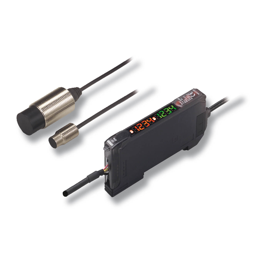
High Precision Positioning Inductive Proximity Sensor
E2C-EDA
• 1 µm resolution
• Precision distance teaching
Ordering Information
Sensors
Sensor Heads
Type
Shielded
Cylindrical
Screw
Flat
Unshielded
Screw
Heat-resistant
Screw
Note 1. A Protective Spiral Tube is provided with models ending in the suffix -S. (example: E2C-ED01-S).
2. Two cable lengths are available. (3-dia.: free-cut type, Heat-resistant type: standard-length only).
Overall length of the standard-length type: 2.5 m, Length from the Sensor Head to the Preamplifier: 2.0 m (Example: E2C-ED01)
Overall length of the free-cut type: 3.5 m, Length from the Sensor Head to the Preamplifier: 0.5 m for models ending in the suffix -F (ex-
ample: E2C-ED01F).
3. Models ending in the suffix -S that come with Protective Spiral Tubes and free-cut models ending in the suffix -F are made-to-order prod-
ucts.
E2C-EDA
Appearance
3 dia. × 18 mm
0.6 mm
5.4 dia. × 18 mm
8 dia. × 22 mm
M10 × 22 mm
30 × 14 × 4.8 mm
M18 × 46.3 mm
M12 × 22 mm
Sensing distance
Repeat accuracy
1 µm
1 µm
1 mm
2 µm
2 mm
2 µm
2 mm
2 µm
5 mm
5 µm
7 mm
2 µm
2 mm
Model
E2C-EDR6-F (See note 2.)
E2C-ED01-@ (See notes 1, 2, and
3.)
E2C-ED02-@ (See notes 1, 2, and
3.)
E2C-EM02-@ (See notes 1, 2, and
3.)
E2C-EV05-@ (See notes 1, 2, and
3.)
E2C-EM07M-@ (See notes 1, 2, and
3.)
E2C-EM02H (See note 2.)
D-83
Advertisement
Table of Contents

Related Manuals for Omron E2C-EDA


Summary of Contents for Omron E2C-EDA
-
Page 1: Ordering Information
Overall length of the standard-length type: 2.5 m, Length from the Sensor Head to the Preamplifier: 2.0 m (Example: E2C-ED01) Overall length of the free-cut type: 3.5 m, Length from the Sensor Head to the Preamplifier: 0.5 m for models ending in the suffix -F (ex- ample: E2C-ED01F). - Page 2 Cable, and AC adapter pro- vided as accessories E3X-MC11-C1-SV2 Mobile Console E3X-MC11-H1 Head E39-Z12-1 Cable (1.5 m) Note: Use the E3X-MC11-SV2 Mobile Console with E2C-EDA-series Amplifier Units. If you use a Mobile Console like the E3X-MC11-S, some functions may not operate. D-84 Inductive Sensors...
-
Page 3: Specifications
Preamplifer Mounting Brackets, Instruction Manual Note 1. The repeat accuracy and temperature characteristic are for a standard sensing object positioned midway through the rated sensing distance. 2. A sudden temperature rise even within the rated temperature range may degrade characteristics. - Page 4 Select from OFF-delay, ON-delay, or one-shot timer. 1 ms to 5 s (1 to 20 ms set in 1-ms increments, 20 to 200 ms set in 10-ms increments, 200 ms to 1 s set in 100-ms increments, and 1 to 5 s set in 1 s-increments) Zero-reset Negative values can be displayed.
-
Page 5: Engineering Data
Engineering Data Sensing Distance vs. Display Values E2C-EDR6-F E2C-ED01(-@) E2C-ED02(-@)/EM02(-@) 4000 4000 4000 3000 3000 3000 Fine Fine Fine 2000 2000 2000 positioning positioning positioning at 0.9 mm at 3 mm at 1.5 mm 1500 1500 1500 1000 1000 1000... - Page 6 Influence of Sensing Object Size and Material E2C-EDR6-F E2C-ED01(-@) E2C-ED02(-@)/EM02(-@) Iron Iron Iron Stainless Stainless Stainless Aluminium Aluminium Aluminium Length of sensed object d (mm) Length of sensed object d (mm) Length of sensed object d (mm) E2C-EM07(-@) E2C-EV05(-@) E2C-EM02H...
- Page 7 E2C-ED02(-@)/EM02(-@) 0.35 0.55 0.30 0.50 0.25 0.45 −20 −20 −20 Ambient temperature of Sensor Head (˚C) Ambient temperature of Sensor Head (˚C) Ambient temperature of Sensor Head (˚C) E2C-EM07(-@) E2C-EV05(-@) E2C-EM02H −20 −20 −50 Ambient temperature of Sensor Head (˚C) Ambient temperature of Sensor Head (˚C)
-
Page 8: Operation
(Between brown and black lines) Note 1. Setting Areas for Twin-output Models Normally open: ON between the thresholds for Channel 1 and Channel 2 Normally closed: OFF between the thresholds for Channel 1 and Channel 2 2. Timing Charts for Timer Settings (T: Set Time) -
Page 9: Timing Chart
(Between blue and black lines) Note 1. Setting Areas for Twin-output Models Normally open: ON between the thresholds for Channel 1 and Channel 2 Normally closed: OFF between the thresholds for Channel 1 and Channel 2 2. Timing Charts for Timer Settings (T: Set Time) - Page 10 Connecting Sensor Heads Connecting and Disconnecting Sensor Heads 1. Open the protective cover. 2. Making sure that the lock button is up, insert the fibers all the way to the back of the Connector insertion opening. DIN rail DIN rail Sensor Head Connector Clips 2.
- Page 11 Mounting a Communications Head for the Mobile Console Effects of Surrounding Metal Leave a space of at least 20 mm on the left side of the Units for a • Provide a minimum distance between the Sensor and the sur- Mobile Console Communications Head.
- Page 12 5.2 dia. 15.8 20.6 E2C-ED01(-F) Vinyl-insulated round cable Vinyl-insulated round coaxial cable 3.4 dia., 3 cores 2.5 dia., 1 core Standard: 0.5 m/-F: 3 m Standard: 2 m/-F: 0.5 m 5.4 dia. Connector 5.2 dia. 15.8 20.6 E2C-ED02(-F) Vinyl-insulated round cable Vinyl-insulated round coaxial cable 3.4 dia., 3 cores...
- Page 13 Vinyl-insulated round cable Vinyl-insulated round coaxial cable 29 dia. 46.3 3.4 dia., 3 cores 2.5 dia., 1 core (11.3) Standard: 0.5 m/-F: 3 m Standard: 2 m/-F: 0.5 m 9.8 dia. 15.7 dia. M18 × 1 Connector Clamping nut 5.2 dia.
- Page 14 Amplifier Units Amplifier Units with Cables E2C-EDA11 Main display Circle ( ): Fine positioning indicator E2C-EDA21 Ellipse ( ): Operation indicators (2 channels) E2C-EDA41 E2C-EDA51 Vinyl-insulated round cable, 4 dia., 4 cores Sub-display Operation indicator (Conductor cross-sectional area: 0.2 mm insulation diameter: 1.1 dia.)
- Page 15 Amplifier Units with Connectors E2C-EDA6 Main display Circle ( ): Fine positioning indicator E2C-EDA7 Ellipse ( ): Operation indicators (2 channels) E2C-EDA8 E2C-EDA9 Sub-display Operation indicator Connector 36.7 With Mounting Bracket Attached 3.9 × 3 38.8 =11.7 The Mounting Bracket can 35.8...
- Page 16 ALL DIMENSIONS SHOWN ARE IN MILLIMETERS. To convert millimeters into inches, multiply by 0.03937. To convert grams into ounces, multiply by 0.03527. Cat. No. D101-E2-01A-X In the interest of product improvement, specifications are subject to change without notice. D-98 Inductive Sensors...
Need help?
Do you have a question about the E2C-EDA and is the answer not in the manual?
Questions and answers