Advertisement
Table of Contents
Transponder
Transponder
F
DELAY
X Type:
Build Level: Intermediate
Based On: EQD® Disaster Transport Jr™
From the
Earthquaker Devices website
"The Disaster Transport JR is an analog voiced digital delay with 625ms delay time with an all
analog dry signal path and true bypass switching. It was designed as an anti-modern delay for
those who appreciate a nice vintage tape echo with all it's peculiarities. Its unique tone control
doubles as a noise filter on longer delay settings and really helps the delay shine with a dirty signal.
The mix control allows you to boost the effected signal to nearly 4x the original signal level and
the repeats control goes from one signal repeat to near infinite repeats all the way through to self
oscillation."
The Disaster Transport Jr™ is essentially a Tonepad Rebote 2.5 circuit with a lot of altered
values. It's the YetAnotherReBote of delays. And, it is a fine sounding PT2399 delay being that. In
addition to the altered voicing, a Big Muff tone control has been added to the wet signal (you might
remember the mbp Zero Point SDX2 from way back in 2015) and clipping diodes in the feedback
path. The Transponder adds deadastronaut's
•
MIX: Amount of wet (delay) signal mixed with the dry.
•
TIME: Delay time (up to around 600ms or so).
•
RPT: Delay repeats from one to "infinity" and/or self-oscillation.
•
TONE: A Big Muff style tone control with unique tonal shaping.
•
MOD: When switched on (right pos.), a subtle envelope-controlled modulation is added to the
wet signal which is controlled by picking dynamics.
Terms of Use:
You are free to use purchased Transponder circuit boards for both DIY and small commercial operations. You may not offer Transponder PCBs for
resale or as part of a "kit" in a commercial fashion. Peer to peer re-sale is fine, though.
Technical assistance
for is available via the
available to respond via email in a timely and continuous manner, and (2) posting technical problems and solutions in the forum creates a record from which other
members may benefit.
All copyrights and registered trademarks are property of their original owners. Any mention of trademarked or intellectual properties in this documents is purely for
comparative purposes.
Overview
envelope modulation trick
Controls
madbeanpedals
forum. Please go there rather than emailing me for personal assistance. This is because (1) I'm not always
Last Updated:
April 25, 2024 9:20 AM
© 2024
madbeanpedals
to round out the features.
Advertisement
Table of Contents

Related Manuals for madbeanpedals Transponder


Summary of Contents for madbeanpedals Transponder
- Page 1 Terms of Use: You are free to use purchased Transponder circuit boards for both DIY and small commercial operations. You may not offer Transponder PCBs for resale or as part of a “kit” in a commercial fashion. Peer to peer re-sale is fine, though.
-
Page 2: Parts Layout
Parts Layout Transponder pg. 2... -
Page 3: Component Values
Component Values Transponder pg. 3... - Page 4 Trace Layout - Outer Layers Transponder pg. 4...
- Page 5 Trace Layout - Inner Layers Transponder pg. 5...
- Page 6 Wiring Unless otherwise noted, all Standard Series projects have the same wiring regardless of which 3PDT bypass board is used. A 6-pin, 2” ribbon cable is recommended for soldering the connections between the two PCBs. Transponder pg. 6...
- Page 7 B.O.M. Resistors Caps Diodes 220n 1n914 470k 100pF 1n914 470k 1n5817 220k TL072 PT2399 100k Regulators 78L05 Switches 100n 100n On/On Pots 100n TONE 25kB TIME 50kB 220k 100uF 100n 10uF 100n 100n 470n 100uF 100n 10uF Transponder pg. 7...
-
Page 8: Shopping List
PCB Right Angle 16mm 25kB PCB Right Angle 16mm 50kB PCB Right Angle 16mm Additional Hardware (1) 1590B enclosure (2) Lumberg 1/4” Compact mono jacks (1) Slim 2.1mm DC jack (1) Standard 3PDT footswitch (1) 5mm LED Transponder pg. 8... - Page 9 Build Notes • The Transponder should be a fairly easy build, but I recommend it as a third or fourth build if you are completely new to DIY. It is a dense circuit board and some experience in component population and soldering would be advantageous.
-
Page 10: Circuit Voltages
PT2399 4.60 5.01 4.62 2.51 4.50 0.00 4.60 2.81 4.60 4.61 0.73 9.20 0.76 78L05 2.51 9.20 2.51 0.00 2.51 5.01 2.51 2.52 2.51 2.51 9.44vDC One Spot supply Current Draw: ~25mA Knobs @ 50%, Switch Left Transponder pg. 10... - Page 11 Link to Tayda Standard Series master drill template Hardware 1590B enclosure 16mm pots Lumberg 1/4” Compact mono jacks Slim 2.1mm DC jack Standard 3PDT footswitch 5mm LED NOTE: Different 1/4” and DC jack styles may require different sized drill holes. Transponder pg. 11...
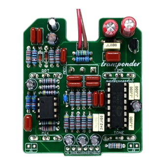
- Page 12 Build Pic Transponder pg. 12...
- Page 13 Schematic Transponder pg. 13...
Need help?
Do you have a question about the Transponder and is the answer not in the manual?
Questions and answers