Advertisement
Table of Contents
Ambulator
Ambulator
F
COMPRESSOR
X Type:
Build Level: Beginner
Based On: MXR® Dyna Comp™
From the
Jim Dunlop
"Released in 1972, the Dyna Comp Compressor featured simple, straightforward controls—labeled
Output and Sensitivity—to govern the volume and compression levels, respectively. Inside, it
contained the coveted CA3080 metal can integrated circuit, which remains a key component to its
sound and vibe.
The original Dyna Comp Compressor was an instant hit, finding its way into the signal chains of
monster players such as Lowell George and Bonnie Raitt, who favored it for the sweet sustain it
lent to their slide work, and David Gilmour, who liked how the Dyna Comp Compressor could make
his single-note lines bloom and soar. Other prominent guitarists who would rely on the Dyna Comp
Compressor include Andy Summers—his popping, ringing clean chords are a perfect illustration of
the pedal's sonic mojo."
•
LEVEL: Total effect output.
•
SUS: Compression amount.
•
BIAS: This trimmer sets the bias currents to the positive and negative input terminals of the
OTA device.
Further study:
https://www.electrosmash.com/mxr-dyna-comp-analysis
Terms of Use:
You are free to use purchased Ambulator circuit boards for both DIY and small commercial operations. You may not offer Ambulator PCBs for
resale or as part of a "kit" in a commercial fashion. Peer to peer re-sale is fine, though.
Technical assistance
for is available via the
available to respond via email in a timely and continuous manner, and (2) posting technical problems and solutions in the forum creates a record from which other
members may benefit.
All copyrights and registered trademarks are property of their original owners. Any mention of trademarked or intellectual properties in this documents is purely for
comparative purposes.
website:
madbeanpedals
forum. Please go there rather than emailing me for personal assistance. This is because (1) I'm not always
Last Updated:
April 25, 2024 9:19 AM
© 2024
madbeanpedals
Overview
Controls
Advertisement
Table of Contents

Related Manuals for madbeanpedals Ambulator


Summary of Contents for madbeanpedals Ambulator
- Page 1 Terms of Use: You are free to use purchased Ambulator circuit boards for both DIY and small commercial operations. You may not offer Ambulator PCBs for resale or as part of a “kit” in a commercial fashion. Peer to peer re-sale is fine, though.
-
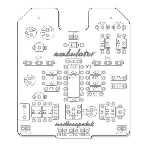
Page 2: Parts Layout
Parts Layout Ambulator pg. 2... -
Page 3: Component Values
Component Values Ambulator pg. 3... - Page 4 Trace Layout Ambulator pg. 4...
- Page 5 Wiring Unless otherwise noted, all Standard Series projects have the same wiring regardless of which 3PDT bypass board is used. A 6-pin, 2” ribbon cable is recommended for soldering the connections between the two PCBs. Ambulator pg. 5...
- Page 6 B.O.M. Resistors Caps Diodes 1n914 1n914 1n5817 Transistors Q1 - Q5 2n3904 CA3080 470k Trimmers 150k 10uF BIAS Pots 100n 100uF 50kA 10uF 500kB 150k Ambulator pg. 6...
-
Page 7: Shopping List
Bourns 3362p or 6mm 50kA PCB Right Angle 16mm 500kB PCB Right Angle 16mm Additional Hardware (1) 1590B enclosure (2) Lumberg 1/4” Compact mono jacks (1) Slim 2.1mm DC jack (1) Standard 3PDT footswitch (1) 5mm LED Ambulator pg. 7... - Page 8 I highly recommend reading the Dyna Comp analysis article on the Electro Smash website. There are a few mod suggestions in the article, too. Note the different component numberings with the Ambulator if you decide to try any them. https://www.electrosmash.com/mxr-dyna-comp-analysis Ambulator pg.
-
Page 9: Circuit Voltages
Circuit Voltages CA3080 2n3904 ~275mV 9.11 4.55 16mV 4.55 2n3904 0.66 9.11 2.42 9.26 2n3904 ~19mV 2n3904 9.26 9.26 9.09 1.79 8.64 1.27 2n3904 7.44 2.42 1.83 9.44vDC One Spot supply Current Draw: ~2mA Knobs @ 50% Ambulator pg. 9... - Page 10 Link to Tayda Standard Series master drill template Hardware 1590B enclosure 16mm pots Lumberg 1/4” Compact mono jacks Slim 2.1mm DC jack Standard 3PDT footswitch 5mm LED NOTE: Different 1/4” and DC jack styles may require different sized drill holes. Ambulator pg. 10...
- Page 11 Build Pic Ambulator pg. 11...
- Page 12 Schematic Ambulator pg. 12...
Need help?
Do you have a question about the Ambulator and is the answer not in the manual?
Questions and answers