Advertisement
NATIONAL
INSTRUMENTS
The Software is the Instrument
Isothermal Terminal Block
This guide describes how to install and use the TBX-1303 32-channel isothermal terminal block
with SCXI-1100 and SCXI-1102 modules.
Introduction
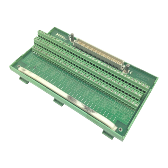
The TBX-1303 32-channel isothermal terminal block is a DIN rail-mountable terminal block that
consists of a shielded board with screw terminals to connect to the SCXI-1100 or
SCXI-1102 module input connector. The TBX-1303 has a high-accuracy thermistor, cold-
junction temperature sensor and an isothermal copper plane to minimize the temperature
gradients across the screw terminals when you measure with thermocouples. The TBX-1303
mounts on most European standard DIN EN mounting rails.
The terminal block has 108 screw terminals for easy connection. Thirty-two sets of three screw
terminals connect to the 32 differential inputs of the SCXI module and provide a shield for each
input. Four terminals connect to the SCXI module OUTPUT, AOREF, and AIREF pins and to
the SCXIbus guard. One pair of terminals labeled GND connects to the chassis ground pins of
the SCXI module. All of the other terminals—OUT0+, OUT0-, OUT1+, OUT1-, and their
shields—are reserved for future use.
The TBX-1303 has a pullup resistor connected between CH+ and +5 V and a bias resistor
connected between CH- and chassis ground. These resistors help you detect open thermocouples
by detecting module amplifier output saturation.
What You Need to Get Started
TBX-1303 32-channel isothermal terminal block kit
TBX-1303 32-channel isothermal terminal block
TBX-1303 32-Channel Isothermal Terminal Block Installation Guide
One package of four 10 MΩ resistor networks
1
/
in. flathead screwdriver
8
SCXI chassis
_____________________________
Product and company names are trademarks or trade names of their respective companies.
321137A-01
®
®
TBX-1303 32-Channel
© 1996 National Instruments Corporation. All rights reserved.
Installation Guide
March 1996
Advertisement
Table of Contents

Related Manuals for National Instruments TBX-1303


Summary of Contents for National Instruments TBX-1303
- Page 1 SCXI module. All of the other terminals—OUT0+, OUT0-, OUT1+, OUT1-, and their shields—are reserved for future use. The TBX-1303 has a pullup resistor connected between CH+ and +5 V and a bias resistor connected between CH- and chassis ground. These resistors help you detect open thermocouples by detecting module amplifier output saturation.
-
Page 2: Installation
No. 1 Phillips-head screwdriver Installation Perform the following steps to mount your cable assembly and connect the TBX-1303 to your SCXI module. Refer to Figures 1 and 2 as needed. 1. Turn off your SCXI chassis. 2. Turn off the computer that contains your data acquisition (DAQ) device or disconnect the device from your SCXI chassis. - Page 3 5. Place one jack screw as shown in Figure 2. 6. While holding the jack screw in place, insert the lockwasher and then the nut. Use long-nose pliers to do this. 7. Tighten the nut by holding it firmly and rotating the jack screw with a inch wrench.
- Page 4 Backshell Mounting Ear Figure 3. Connecting the SH96-96 Cable to the SCXI Module 13. Connect the other end of your cable assembly to your TBX-1303 terminal block connector and secure the cable by tightening both backshell mounting screws. See Figure 4.
- Page 5 Note: The SH96-96 cable is not shown in the exact position for proper connection to the terminal block connector. See Figure 5 for the completed connection. Figure 4. Connecting the SH96-96 Cable to the TBX-1303 Terminal Block Figure 5. The Completed Installation...
-
Page 6: Signal Connection
Signal Connection Warning: Do not connect hazardous voltage levels to this product. To connect your field signals to the TBX-1303 for use with the SCXI-1100 or SCXI-1102 modules, refer to Figures 4 and 6 as you perform the following instructions: 1. - Page 7 Figure 6. TBX-1303 Parts Locator Diagram Temperature Sensor and Switch Configuration To enable you to use thermocouples with SCXI modules, the TBX-1303 terminal block has a thermistor temperature sensor for cold-junction compensation. You can connect the temperature sensor to an SCXI module in either of two ways: •...
-
Page 8: Temperature Sensor Output And Accuracy
Note: On the SCXI-1102 module, the MTEMP and DTEMP modes are equivalent. Temperature Sensor Output and Accuracy The TBX-1303 temperature sensor voltage output varies from 1.91 to 0.58 V over the 0° to 55° C temperature range. The temperature sensor output accuracy is shown in Table 2. -
Page 9: Configuring The Resistor Networks
RP6, RP7, and RP8. With this recommended configuration, it does not matter whether the thermocouples are ground- referenced or floating. The TBX-1303 terminal block has a pullup resistor connected between CH+ and +5 V and a bias resistor connected between CH- and chassis ground. - Page 10 Figure 7 shows how the pullup and bias resistors are connected to the CH± inputs. pullup (RP1, RP2, RP3, RP4) (in sockets) SCXI Module Screw Terminals bias (RP5, RP6, RP7, RP8) (in sockets) Figure 7. Resistor Connections Table 3 shows the relationship between the channel input signals and the resistor networks. Table 3.
-
Page 11: Open Thermocouple Detection
SCXI module channel is saturated. The pullup and bias resistors on the TBX-1303 saturate the channel by applying +5 V at the input of an open channel. Notice that this will result in saturation to either of the positive or negative rails. - Page 12 200 µs at a gain of 100 or higher, which corresponds to a sample rate of 5 kHz. With the 10 Ω bias resistors installed in the TBX-1303, you can measure accurately at the module’s maximum sampling rate, but the open thermocouple channel may not saturate if the interchannel delay is less than 200 µs or if the sample rate is more than 5 kHz at a gain of 100 or...
- Page 13 Errors Due to Open-Thermocouple Detection Circuitry Open-thermocouple detection circuitry can cause two types of measurement errors. These errors are the results of common-mode voltage at the input of the SCXI module and current leakage into your signal leads. Common-Mode Voltage at the Input of the SCXI Module With 10 MΩ...
-
Page 14: Temperature Sensor Circuit Diagram
Temperature Sensor Circuit Diagram The circuit diagram in Figure 9 provides details about the TBX-1303 temperature sensor. +5 V 4.7 kΩ 2.5 V 5 kΩ LM 4040 0.1% MTEMP 2.5 V 0.1 µF 0.1% DTEMP 10 µF 5 kΩ 0.1 µF...
Need help?
Do you have a question about the TBX-1303 and is the answer not in the manual?
Questions and answers