
Related Manuals for UNI-T UTG2000X Series


Summary of Contents for UNI-T UTG2000X Series
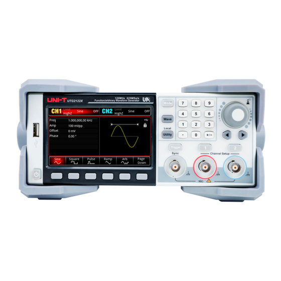
- Page 1 User’s Manual UTG2000X Series User’s Manual UTG2000X Series Function/Arbitrary Waveform Generator V1.0 2024.3...
-
Page 2: Copyright Information
UNI-T is the registered trademark of Uni-Trend Technology (China) Co., Ltd. Warranty Service UNI-T warrants that the product will be free from defects for a three-year period. If the product is re-sold, the warranty period will be from the date of the original purchase from an authorized UNI-T distributor. - Page 3 This warranty is written by UNI-T for this product, and it is used to substitute any other express or implied warranties. UNI-T and its distributors do not offer any implied warranties for merchant ability or applicability purposes.
-
Page 4: Chapter 1 User's Guide
Users must follow the following conventional safety precautions in operation, service and maintenance of this device. UNI-T will not be liable for any personal safety and property loss caused by the user’s failure to follow the following safety precautions. -
Page 5: Safety Sign
User’s Manual UTG2000X Series “Caution” indicates the presence of a hazard. It reminds users to pay attention to a certain operation process, operation method or similar. Product damage or loss of important data may occur if the rules in the “Caution” statement are not properly Caution executed or observed. - Page 6 User’s Manual UTG2000X Series copier in the office. CATII: Primary electrical circuit of the electrical equipment connected to the indoor socket via the power cord, such as mobile tools, home appliances, etc. Household appliances, portable tools CAT II (e.g. electric drill), household sockets, sockets more than 10 meters away from CAT III circuit or sockets more than 20 meters away from CAT IV circuit.
-
Page 7: Ac Power Supply
Power fuse specifications (Class T, rated current 5A, rated voltage 250V) by the maintenance personnel authorized by UNI-T. There are no components available to operators inside. Do not remove the Disassembly protective cover. -
Page 8: Environmental Requirements
If this device may be faulty, please contact the authorized maintenance Abnormality personnel of UNI-T for testing. Any maintenance, adjustment or parts replacement must be done by the relevant personnel of UNI-T. Do not block the ventilation holes at the side and back of this device;... -
Page 9: Connecting Power Supply
User’s Manual UTG2000X Series Unless otherwise specified, operating temperature is 10 to +40℃; storage temperature is -20 to ﹢60 In operating, humidity temperature below to +35℃, ≤90% RH. (Relative humidity) In non-operating, humidity temperature +35℃ to +40℃, ≤60% RH. (Relative humidity) ... -
Page 10: Preparation Work
SCPI. The detailed information about the installation, remote control mode and the programming, please refer to UTG2000X Series Programming Manual at the official website http:// www.uni-trend.com 1.8 Help Information UTG2000X series function/arbitrary waveform generator has built-in help system for each function key and menu control key. -
Page 11: Chapter 2 Product Introduction
1 μHz. It is an economical, high performance, multifunction function/arbitrary waveform generator. It can generate high precision, stable, pure and low distortion signal. UTG2000X series has convenient operation, superior technical indicators and humanized graphics display. A multi-purpose equipment for the needs of learning, testing and improving work efficiency. -
Page 12: Output Features
User’s Manual UTG2000X Series 2.2 Output Features Channel CH1,CH2 Amplitude 1 mVpp~10 Vpp (50 Ω) Range Sine wave, square wave, pulse wave, ramp wave, arbitrary Waveform wave, noise, DC, harmonic, PRBS, expression AM, FM, PM, ASK, FSK, 3FSK, 4FSK, PSK, BPSK, QPSK, OSK,... - Page 13 User’s Manual UTG2000X Series Function Key Mode, Wave, Utility key to set the modulation, carrier wave parameter and modulating parameter and auxiliary function. Numerical Keyboard Digit key 0-9, decimal point “.”, symbolic key “+/-” for input the parameter. The left key is used to backspace and delete the previous bit of the current input.
-
Page 14: Rear Panel
User’s Manual UTG2000X Series USB interface is used to connect with an external USB storage device. The instrument supports USB FAT32 32G. Through this interface, arbitrary waveform data files saved in USB can be read or imported. In addition, the system of the instrument can be upgraded through this interface. - Page 15 Provides an electrical ground connection for connecting an anti-static wrist strap when moving the instrument or to reduce electrostatic damage (ESD) when connecting DUT. AC power input AC power specification of UTG2000X series, refer to the section of Connecting Power Instruments.uni-trend.com 15 / 134...
-
Page 16: Function Interface
User’s Manual UTG2000X Series Supply. 10. Main power switch When the power switch is “I”, indicating that the instrument is power on. When the power switch is “O”, indicating that the instrument is power off (the power switch on the front panel does not work). - Page 17 User’s Manual UTG2000X Series into a list of parameters. Softkey label: to identify the function menu softkey and the menu operation softkey. Highlight: It indicates that the right center of the label displays the color of the current channel or the gray when the system is being set up, and the font is pure white.
-
Page 18: Chapter 3 Quick Start
User’s Manual UTG2000X Series Chapter 3 Quick Start 3.1 Output Basic Waveform Output Frequency 3.1.1 Default waveform: a sine wave with frequency 1 kHz, amplitude 100 mV peak-to-peak (connect with 50 Ω port) The specific steps to change the frequency to 2.5 MHz are as follows. - Page 19 User’s Manual UTG2000X Series Press Wave Pluse Duty key in turn, use the numerical keyboard to enter 25 and then select the unit of the parameter to %. Symmetry of Ramp Wave 3.1.6 The default frequency of pulse wave is 1 kHz.
-
Page 20: Auxiliary Function
User’s Manual UTG2000X Series 3.2 Auxiliary Function The auxiliary function (Utility) can set the frequency meter, system, for CH1 and CH2. The specific functions are shown in the following table. 3.2.1 Channel Setting Function Menu Function Sub-menu Setting Description Channel output... -
Page 21: Channel Tracking
User’s Manual UTG2000X Series Select the softkey Upper to set the upper limit range of the amplitude. Lower limit of Amplitude Select the softkey Lower to set the lower limit range of the amplitude. Channel Duplication 3.2.2 Select Utility CH Copy key in turn to select the softkey CH1 Copy or CH2 Copy, which is to copy the parameter of the current channel into other channel. - Page 22 User’s Manual UTG2000X Series Select Utility CH Follow key in turn to set the channel tracking function. Channel Tracking Select the softkey CH Follow to “OFF” or “ON”. Tracking Type Select the softkey Follow Type to “parameter tracking” or “channel tracking”.
- Page 23 User’s Manual UTG2000X Series When t the softkey Rate is selected, use numerical keyboard to enter the ratio. Phase Tracking The softkey PhasFollow can be selected in the channel tracking menu. The phase tracking mode of CH1 and CH2 can set to ratio, deviation or OFF. CH1 and CH2 are reference sources to each other.
-
Page 24: Frequency Meter
User’s Manual UTG2000X Series Frequency Meter 3.2.5 This function/arbitrary waveform generator can measure the frequency and duty cycle of compatible TTL signals. The range of measurement frequency is 100 mHz~200 MHz. When use the frequency meter, a compatible TTL signal is imported via the external digital modulation or frequency meter interface (FSK/Trig/Counter). -
Page 25: Network Setting
User’s Manual UTG2000X Series Press UtilitySystem Manage UserConfirm key in turn, and press the softkey Delete All to delete all the user-defined arbitrary waves in the current file folder. Export the user-defined arbitrary wave Press UtilitySystem Manage UserConfirm key in turn, and select the arbitrary wave “ALT_03.bsv”... - Page 26 User’s Manual UTG2000X Series instrument will automatically load the set IP address when the instrument is rebooted. Subnet mask The format of subnet mask address is nnn.nnn.nnn.nnn,the range of nnn is 0~255. It is recommended that you consult network administrator for an available subnet mask. Select the softkey Mask, use the numerical keyboard, rotary knob or arrow key to enter subnet mask.
- Page 27 User’s Manual UTG2000X Series Note: As the system has several menus, there are two pages, press the softkey Next to turn the page. Language Press the softkey Language to set the system language to simplified Chinese, English or German. Phase Synchronization Select the softkey Phase Sync to select “Independent”...
-
Page 28: Chapter 4 Advanced Application
User’s Manual UTG2000X Series Chapter 4 Advanced Application This chapter is to introduce modulation of AM, FM, PM, ASK, FSK, 3FSK, 4FSK, PSK, BPSK, QPSK, OSK, SUM, DSB-AM, QAM and PWM. Press Mode key to enter modulation mode and the key will light up. Press it again to exit the modulation mode and the key will light off. - Page 29 User’s Manual UTG2000X Series Set Carrier Wave Frequency The frequency range of the carrier wave can be set differently. The default frequency of the carrier wave is 1 kHz. The frequency of each carrier wave are shown the following table.
- Page 30 User’s Manual UTG2000X Series Falling ramp wave: Symmetry is 0 %. Arbitrary wave: The length of arbitrary wave limits at 4 kpts by the method of automatic extracting point when arbitrary wave is the modulation wave. Noise Wave: White Gauss noise Modulation Frequency Setting The frequency range is 2 mHz~1 MHz (the default is 100 Hz).
- Page 31 User’s Manual UTG2000X Series signal with frequency 10 kHz, amplitude 200 mVpp, duty ratio 45 % as the carrier wave and set modulation depth to 80 % at last. The setting steps are as follows. 1) Enabling AM mode Press Mode ModWave AM key in turn to turn on AM mode.
- Page 32 User’s Manual UTG2000X Series Press the softkey Freq to set the frequency, use the numerical keyboard to enter 10 and then select the unit of parameter to kHz. Press the softkey Amp soft key to set the amplitude, use the numerical keyboard to enter 200 and then select the unit of parameter to mVpp.
- Page 33 User’s Manual UTG2000X Series 5) Enabling channel output Press CH1 key, if the key is illumined which means the channel output is enabled. To view the modulation waveform of AM through an oscilloscope as shown in the following figure. Instruments.uni-trend.com...
-
Page 34: Frequency Modulation(Fm
User’s Manual UTG2000X Series Frequency Modulation(FM) 4.1.2 In FM mode, modulated wave is consist of the carrier wave and the modulation wave. The frequency of the carrier wave will changed with the amplitude of the modulation wave. Press ModeMod FM key in turn to turn on FM mode, the instrument will output the modulated waveform according to the currently modulation wave and the carrier wave. - Page 35 User’s Manual UTG2000X Series be sine wave, square wave, rising ramp wave, falling ramp wave, arbitrary wave and noise wave. The default is sine wave. When FM mode is enabled, the default modulation wave is sine wave. The modulation wave can be changed by using multifunction rotary knob or pressing the softkey ModWave in FM mode.
- Page 36 User’s Manual UTG2000X Series The sum of the frequency deviation and the carrier wave frequency ≤ the maximum of the currently carrier frequency, if the frequency deviation value is invalid, the instrument will automatically limits the deviation to the maximum which allowed by the currently carrier frequency.
- Page 37 User’s Manual UTG2000X Series 3) Set carrier wave and parameter Press Wave key to enter the carrier wave page and then select square wave as the carrier wave (the default is sine wave). Press the softkey Freq to set the frequency, use the numerical keyboard to enter 10 and then select the unit of parameter to kHz.
- Page 38 User’s Manual UTG2000X Series 4) Set Frequency deviation After the parameter setting of the carrier wave is completed, press Mode ModWave FM key in turn to enter FM setting, press the softkey FreqDev, use the numerical keyboard to enter 5 and then select the unit of parameter to kHz.
-
Page 39: Phase Modulation(Pm
User’s Manual UTG2000X Series To view the modulation waveform of FM through an oscilloscope as shown in the following figure. Phase Modulation(PM) 4.1.3 In PM mode, modulated wave is consist of the carrier wave and the modulation wave. The phase of the carrier wave will changed with the amplitude of the modulation wave. - Page 40 User’s Manual UTG2000X Series Select Carrier Wave The carrier wave can be sine wave, square wave, ramp wave or arbitrary wave. The default is sine wave. After PM mode is selected, press Wave key to enter the carrier wave interface.
- Page 41 User’s Manual UTG2000X Series Arbitrary wave: The length of arbitrary wave limits at 4 kpts by the method of automatic extracting point when arbitrary wave is the modulation wave. Noise Wave: White Gauss noise Modulation Frequency Setting The frequency range is 2 mHz~1 MHz (the default is 100 Hz). When PM mode is enabled, the default frequency of the modulation wave is 100 Hz.
- Page 42 User’s Manual UTG2000X Series 2) Set modulation signal Base on the step 1, press the softkey ModFreq and use the numerical keyboard to enter 200 and then select the unit to Hz. 3) Set carrier wave and parameter Press Wave key to enter the carrier wave page and then select square wave as the carrier wave (the default is sine wave).
- Page 43 User’s Manual UTG2000X Series Press the softkey Freq key to set the frequency, use the numerical keyboard to enter 900 and then select the unit of parameter to Hz. Press the softkey Amp to set the amplitude, use the numerical keyboard to enter 100 and then select the unit of parameter to mVpp.
- Page 44 User’s Manual UTG2000X Series 5) Enabling the channel output Press CH1 key, if the key is illumined which means the channel output is enabled. To view the modulation waveform of PM through an oscilloscope as shown in the following figure.
-
Page 45: Amplitude Shift Keying(Ask
User’s Manual UTG2000X Series Amplitude Shift Keying(ASK) 4.1.4 In ASK mode, change the amplitude of carrier signal to express the digital signal as “0” or “1”. It outputs the carrier signals with different amplitude according to the logic level of modulation signal. - Page 46 User’s Manual UTG2000X Series Set Carrier Wave Frequency Refer to Carrier Wave Frequency in AM mode. Select Modulation Source The modulation source of this instrument can select internal or external. When ASK mode is enabled, the default modulation source is internal. It can switch to external by using multifunction rotary knob or pressing the softkey Source...
- Page 47 User’s Manual UTG2000X Series logic level of external input is low; it outputs the hopping frequency when the logic level of external input is high. ASK Rate Setting When ASK mode is enabled, it can set ASK rate (2 mHz~100 kHz). The default is 100 Hz. It can be change by using multifunction rotary knob and arrow keys or pressing the softkey Rate, and then use the numerical keyboard to enter number and select unit softkey to complete the setting.
- Page 48 User’s Manual UTG2000X Series 3) Set carrier signal Press Wave key to enter the carrier wave page and then select sine wave as the carrier wave (the default is sine wave). Press the softkey Freq key to set the frequency, use the numerical keyboard to enter 15 and then select the unit of parameter to kHz.
- Page 49 User’s Manual UTG2000X Series 4) Enabling channel output Press CH1 key, if the key is illumined which means the channel output is enabled. To view the modulation waveform of ASK through an oscilloscope as shown in the following figure. Instruments.uni-trend.com...
- Page 50 User’s Manual UTG2000X Series Frequency Shift Keying(FSK) 4.1.5 In FSK mode, it can set the switch rate between the frequency of carrier wave and hopping frequency. Select FSK Select Mode Mod FSK key in turn to turn on FSK mode, the waveform generator will output the modulated waveform according to the currently setting.
- Page 51 User’s Manual UTG2000X Series The modulation source of this instrument can select internal or external. When FSK mode is enabled, the default modulation source is internal. It can switch to external by using multifunction rotary knob or pressing the softkey Source...
- Page 52 User’s Manual UTG2000X Series or pressing the softkey Rate, and then use the numerical keyboard to enter number and select unit softkey to complete the setting. Comprehensive Example In FSK mode, set a sine wave with 2 kHz, 1 Vpp as the carrier signal, the hopping frequency is 800 Hz, switching the carrier frequency and hopping frequency based on the frequency of 200 Hz.
- Page 53 User’s Manual UTG2000X Series to Hz. 4) Set carrier signal Press Wave key to enter the carrier wave page and then select sine wave as the carrier wave (the default is sine wave). Press the softkey Freq to set the frequency, use the numerical keyboard to enter 2 and then select the unit of parameter to kHz.
- Page 54 User’s Manual UTG2000X Series 5) Enabling channel output Press CH1 key, if the key is illumined which means the channel output is enabled. To view the modulation waveform of FSK through an oscilloscope as shown in the following figure. Instruments.uni-trend.com...
- Page 55 User’s Manual UTG2000X Series Three Frequency Shift Keying(3FSK) 4.1.6 In 3FSK mode, the function/arbitrary waveform generator can move among three preset frequency(carrier frequency and two hopping frequency). It outputs the frequency of carrier signal or hopping frequency according to the logic of modulation signal. The modulation mode of each channel are independent, user can set the same or different modulation mode for each channels.
- Page 56 User’s Manual UTG2000X Series Refer to Carrier Wave Frequency in AM mode. Set Hopping Wave Use multifunction rotary knob and arrow keys to set the hopping frequency 1 (or hopping frequency 2), or press the softkey HopFreq1(or HopFreq2), and use the numerical keyboard to enter number and select the unit softkey to complete the setting.
- Page 57 User’s Manual UTG2000X Series Press the softkey Freq to set the frequency, and then use the numerical keyboard to enter 2 kHz. Press the softkey Amp to set the amplitude, and then use the numerical keyboard to enter 1 Vpp.
- Page 58 User’s Manual UTG2000X Series Press the softkey Rate, use the numerical keyboard to enter 100 Hz. Press the softkey HopFreq1, use the numerical keyboard to enter 1 kHz. Press the softkey HopFreq2, use the numerical keyboard to enter 5 kHz.
- Page 59 User’s Manual UTG2000X Series To view the modulation wave of 3FSK through an oscilloscope as shown in the following figure. Four Frequency Shift Keying(4FSK) 4.1.7 In 4FSK mode, the function/arbitrary waveform generator can move among four preset frequency(carrier frequency and four hopping frequency). It outputs the frequency of carrier signal or hopping frequency according to the logic of modulation signal.
- Page 60 User’s Manual UTG2000X Series Select Carrier Wave Carrier wave of 4FSK can be sine wave, square wave, ramp wave or arbitrary wave (except DC). The default is sine wave. After 4FSK mode is selected, press Wave key to enter the carrier wave interface.
- Page 61 User’s Manual UTG2000X Series 4FSK Rate Setting When the modulation source is internal, the frequency can be switched between the carrier frequency and the hopping frequency. When 4FSK mode is enabled, it can set 3FSK rate (2 mHz~1 MHz). The default is 100 Hz. It can be change by using multifunction rotary knob and...
- Page 62 User’s Manual UTG2000X Series Press the softkey Freq to set the frequency, and then use the numerical keyboard to enter 500 Press the softkey Amp to set the amplitude, and then use the numerical keyboard to enter 1 Vpp. 3) Set hopping frequency and modulation rate When the carrier signal is set, press Mode Mod 4FSK in turn to go back to the following...
- Page 63 User’s Manual UTG2000X Series Press the softkey Rate, use the numerical keyboard to enter 100 Hz. Press the softkey HopFreq1, use the numerical keyboard to enter 2 kHz. Press the softkey HopFreq2, use the numerical keyboard to enter 5 kHz.
- Page 64 User’s Manual UTG2000X Series To view the modulation wave of 4FSK through an oscilloscope as shown in the following figure. Phase Shift Keying(PSK) 4.1.8 In PSK mode, the function/arbitrary waveform generator can move between two preset phases (carrier phase and modulation phase). It outputs the carrier phase or modulation phase according to the logic level of the modulation signal.
- Page 65 User’s Manual UTG2000X Series Select Carrier Wave Carrier wave of PSK can be sine wave, square wave, ramp wave or arbitrary wave (except DC). The default is sine wave. After PSK mode is selected, press Wave key to enter the carrier wave interface.
- Page 66 User’s Manual UTG2000X Series 1) Internal Source When the modulation source is internal, the internal modulation wave is a square sine with duty ratio 50 % (non-adjustable). The frequency between the carrier phase and the modulation phase can be specified by adjusting the PSK rate.
- Page 67 User’s Manual UTG2000X Series and modulation 180°phase based on the frequency of 1 kHz. The setting steps are as follows. 1) Enabling PSK mode Press Mode Mod PSK key in turn to turn on PSK mode. 2) Set carrier signal Press Wave key to enter the carrier wave page and then select sine wave as the carrier wave (the default is sine wave).
- Page 68 User’s Manual UTG2000X Series 3) Set modulation rate Press Wave key to enter the modulation parameter page, and press the softkey Rate, use the numerical keyboard to enter 1 and then select the unit to kHz. 4) Set phase Press the softkey Phase1 and use the numerical keyboard to enter 180, and then select the unit to °.
- Page 69 User’s Manual UTG2000X Series 5) Enabling channel output Press CH1 key, if the key is illumined which means the channel output is enabled. To view the modulation waveform of PSK through an oscilloscope as shown in the following figure. Instruments.uni-trend.com...
- Page 70 User’s Manual UTG2000X Series Binary Phase Shift Keying(BPSK) 4.1.9 In BPSK mode, the function/arbitrary waveform generator can move between preset phase (carrier frequency and modulation phase), it is expressed in 0 and 1. It outputs the carrier phase or modulation phase according to the logic of modulation signal. The modulation mode of each channel are independent, user can set the same or different modulation mode for each channels.
- Page 71 User’s Manual UTG2000X Series Set Carrier Wave Frequency Refer to Carrier Wave Frequency in AM mode. Select Symbol The modulation source of this instrument can select internal. When BPSK mode is enabled, the default symbol is PN3. It can change by using multifunction rotary knob or pressing PNCode...
- Page 72 User’s Manual UTG2000X Series Enabling BPSK mode Press Mode Mod BPSK key in turn to turn on BPSK mode. Set carrier signal Press Wave key to select sine wave as the carrier wave (the default is sine wave), so this step doesn’t need to be changed.
- Page 73 User’s Manual UTG2000X Series 3) Set BPSK bitrate and phase When the carrier signal is set, press Mode Mod BPSK key in turn to go back to the following page to set the modulation parameter. Press the softkey BitRate, use the numerical keyboard to enter 1 kbps.
- Page 74 User’s Manual UTG2000X Series 4) Enabling channel output Press the state of CH1 output to “ON”, or press the quick key CH1 on the front panel to turn on CH1 output, or press the softkey Utility CH1 Setting in turn, and then press CH1 Output key to enable the channel output.
- Page 75 User’s Manual UTG2000X Series Quadrature Phase Shift Keying(QPSK) 4.1.10 In QPSK mode, the function/arbitrary waveform generator can move among four preset phase (carrier frequency and three modulation phase). It outputs the carrier phase or modulation phase according to the logic of modulation signal. The modulation mode of each channel are independent, user can set the same or different modulation mode for each channels.
- Page 76 User’s Manual UTG2000X Series Set Carrier Wave Frequency Refer to Carrier Wave Frequency in AM mode. Select Symbol The modulation source of this instrument can select internal. When QPSK mode is enabled, the default symbol is PN3. It can change by using multifunction rotary knob or pressing the softkey PNCode...
- Page 77 User’s Manual UTG2000X Series 1)Phase 1 is the carrier phase, the default phase is 0°. It can be change by using multifunction rotary knob and arrow keys or pressing the softkey Phase1, and use the numerical keyboard to enter number and then select the unit to complete the setting.
- Page 78 User’s Manual UTG2000X Series Press the softkey Freq, use the numerical keyboard to enter 2 kHz. Press the softkey Amp, use the numerical keyboard to enter Vpp. 3) Set QPSK bitrate and modulation phase When the carrier signal is set, press Mode Mod QPSK key in turn to go back to the following page to set the modulation parameter, as shown in the following figure.
- Page 79 User’s Manual UTG2000X Series Press the softkey BitRate, use the numerical keyboard to enter 1 kbps. It is not necessary to set the phase, use the default value, phase 1 is 0°, phase 2 is 90°, phase 2 is 180° and phase 4 is 270°.
- Page 80 User’s Manual UTG2000X Series Oscillation Keying(OSK) 4.1.11 In OSK mode, the function/arbitrary waveform generator can output a sine signal of intermittent oscillation. When the internal crystal oscillator starts to oscillating, the instrument will output the carrier waveform. The output stops when the internal crystal oscillator stops oscillating.
- Page 81 User’s Manual UTG2000X Series Press Wave key, the selection only has sine wave. Set Carrier Wave Frequency Refer to Carrier Wave Frequency in AM mode. Select Modulation Source The modulation source of this instrument can select internal or external. When OSK mode is enabled, the default modulation source is internal.
- Page 82 User’s Manual UTG2000X Series When the modulation source is internal, the frequency between carrier phase and modulation phase can be set. When OSK modulation is enabled, the OSK rate can be set and the range is 2 mHz~1 MHz, the default is 100 Hz. It can be change by using multifunction rotary knob and arrow keys or pressing the softkey Rate, use the numerical keyboard to enter number and then select the unit to complete the setting.
- Page 83 User’s Manual UTG2000X Series Press the softkey Freq, use the numerical keyboard to enter 2 kHz. Press the softkey Amp, use the numerical keyboard to enter Vpp. 3) Set OSK rate When the carrier signal is set, press Mode Mod OSK key in turn to go back to the following page and then to set modulation parameter.
- Page 84 User’s Manual UTG2000X Series 4) Enabling channel output Press the state of CH1 output to “ON”, or press the quick key CH1 on the front panel to turn on CH1 output, or press the softkey Utility CH1 Setting in turn, and then press CH1 Output key to enable the channel output.
- Page 85 User’s Manual UTG2000X Series SUM Modulation(SUM) 4.1.12 In SUM mode, the modulated wave is consist of carrier wave and modulation wave. The output waveform is sum of the amplitude of the carrier wave multiply by modulation factor and add the amplitude of the modulation wave multiply by modulation factor.
- Page 86 User’s Manual UTG2000X Series Set Carrier Wave Frequency Refer to Carrier Wave Frequency in AM mode. Select Modulation Source The modulation source of this instrument can select internal or external. When SUM mode is enabled, the default modulation source is internal. It can switch to external by using multifunction rotary knob or pressing the softkey Source...
- Page 87 User’s Manual UTG2000X Series Arbitrary wave: The length of arbitrary wave limits at 2 kpts by the method of automatic extracting point when arbitrary wave is the modulation wave. Noise Wave: White Gauss noise 2) External source When the modulation source is external, the modulation wave and modulation frequency will be hidden in parameter list.
- Page 88 User’s Manual UTG2000X Series 2) Set carrier signal Press Wave key to select square wave as the carrier wave (the default is sine wave). Press the softkey Freq to set the frequency, and then use the numerical keyboard to enter 2 kHz.
- Page 89 User’s Manual UTG2000X Series 3) Set the modulation frequency and depth When the carrier signal is set, press Mode Mod SUM key in turn to go back to the following page and then to set modulation parameter. Press the softkey ModFreq to set the frequency, and then use the numerical keyboard to enter 1 kHz.
- Page 90 User’s Manual UTG2000X Series Enabling channel output Press the state of CH1 output to “ON”, or press the quick key CH1 on the front panel to turn on CH1 output, or press the softkey Utility CH1 Setting in turn, and then press CH1 Output key to enable the channel output.
- Page 91 User’s Manual UTG2000X Series Double-sideband Amplitude Modulation(DSBAM) 4.1.13 Select DSBAM Mode Press Mode Mod DSBAM key in turn to turn on DSBAM mode, the waveform generator will output the modulated waveform according to the currently settings. Select Carrier Wave Carrier wave of DSBAM can be sine wave, square wave, ramp wave, pulse wave or arbitrary wave (except DC).
- Page 92 User’s Manual UTG2000X Series Set Carrier Wave Frequency Refer to Carrier Wave Frequency in AM mode. Select Modulation Source The modulation source of this instrument can select internal or external. When DSBAM mode is enabled, the default modulation source is internal. It can switch to external by using multifunction rotary knob or pressing the softkey Source...
- Page 93 User’s Manual UTG2000X Series Arbitrary wave: The length of arbitrary wave limits at 2 kpts by the method of automatic extracting point when arbitrary wave is the modulation wave. Noise Wave: White Gauss noise 2) External source When the modulation source is external, the modulation wave and modulation frequency will be hidden in parameter list.
- Page 94 User’s Manual UTG2000X Series Set carrier signal Press Wave key to select sine wave as the carrier wave (the default is sine wave), so this step doesn’t need to be changed. Press the softkey Freq, and then use the numerical keyboard to enter 2 kHz.
- Page 95 User’s Manual UTG2000X Series Press the softkey ModWave to select square wave. Press the softkey ModFreq and the use the numerical keyboard to enter 1 kHz. 4) Enabling channel output Press the state of CH1 output to “ON”, or press the quick key CH1 on the front panel to turn on CH1 output, or press the softkey Utility CH1 Setting in turn, and then press CH1 Output key...
- Page 96 User’s Manual UTG2000X Series To view the modulation waveform of DSBAM through an oscilloscope as shown in the following figure. Quadrature Modulation(QAM) 4.1.14 In QAM mode, set two signals of the same frequency but with phase difference 90° (usually represented by Sin and Cos) as the carrier wave, use baseband signal to modulate the carrier wave.
- Page 97 User’s Manual UTG2000X Series Select QAM Mode Press Mode Mod QAM key in turn to turn on QAM mode, the waveform generator will output the modulated waveform according to the currently settings. Select Carrier Wave Carrier wave of QAM can only be sine wave. After QAM mode is selected, press Wave key, only sine wave is available in the modulation type on the right.
- Page 98 User’s Manual UTG2000X Series Select Symbol When QAM mode is enabled, the default symbol is PN3. It can be change by using multifunction rotary knob or pressing the softkey PNode PN3 in turn to select PN3, PN5, PN7, PN9, PN11, PN13, PN15, PN17, PN19, PN21, PN23, PN25, PN27, PN29 or PN31.
- Page 99 User’s Manual UTG2000X Series Press the softkey Freq, and then use the numerical keyboard to enter 2 kHz. Press the softkey Amp, and then use the numerical keyboard to enter Vpp. 3) Set modulation parameter When the carrier signal is set, press Wave key to go back to the following page to set the modulation parameter.
- Page 100 User’s Manual UTG2000X Series Press the softkey Map QAM4 in turn to select QAM64. Press the softkey PNCode to pop out the dialog box select PN7. Press the softkey Bitrate and then use the numerical keyboard to enter 100 bps (the default is 100 bps).
-
Page 101: Pulse Width Modulation(Pwm
User’s Manual UTG2000X Series Pulse Width Modulation(PWM) 4.1.15 In PWM mode, the modulated waveform is consist of the carrier wave and the modulation wave. The pulse width of the carrier wave will changed with the amplitude of the modulation wave. - Page 102 User’s Manual UTG2000X Series Set Carrier Wave Frequency Refer to Carrier Wave Frequency in AM mode. Set Modulation Frequency When PWM mode is enabled, the frequency range of modulation wave is 2 mHz~1 MHz (the default is 100 Hz). It can be change by using multifunction rotary knob or pressing the softkey ModFreq, and then use numerical keyboard to enter number and select unit soft key to complete the setting.
- Page 103 User’s Manual UTG2000X Series rising/falling time of 100 ns, and then set the duty cycle deviation to 40 %. The settings steps as following. Enabling mode Press Mode Mod PWM key in turn to turn on PWM mode. 2) Set modulation signal Press the softkey ModFreq, use the numerical keyboard to enter 1 and then select the unit to kHz.
- Page 104 User’s Manual UTG2000X Series 4) Set carrier wave and parameter Press Wave key to enter the carrier wave page and then select pulse wave as the carrier wave (the default is pulse wave). Press the softkey Freq to set the frequency, use the numerical keyboard to enter 10 and then select the unit of parameter to kHz.
- Page 105 User’s Manual UTG2000X Series 5) Enabling Channel Output Press CH1 key, if the key is illumined which means the channel output is enabled. To view the modulation waveform of PWM through an oscilloscope as shown in the following figure. Instruments.uni-trend.com...
-
Page 106: Sweep Frequency
User’s Manual UTG2000X Series 4.2 Sweep Wave Output In frequency sweep mode, the output frequency of the instrument is change from start frequency to stop frequency in a linear, logarithmic or step way. Sine wave, square wave, ramp wave and arbitrary wave (except DC) can all generate the frequency sweep output. -
Page 107: Start And Stop Frequency
User’s Manual UTG2000X Series Start and Stop Frequency 4.2.2 Start frequency and stop frequency is the upper limit and lower limit of frequency for sweep frequency. The function/arbitrary waveform generator is always sweep from the start frequency to the stop frequency and back to the start frequency. - Page 108 User’s Manual UTG2000X Series Sweep Frequency Time 4.2.4 In frequency sweep mode, the frequency sweep time (the range is 1 ms- 500s), the default is 1s. It can be change by pressing the softkey SweepTime and use the numerical keyboard to enter number and then select unit to complete the setting.
- Page 109 User’s Manual UTG2000X Series Press the softkey Amp to set the amplitude, use the numerical keyboard to input 1 and then select the unit of parameter to Vpp. Press the softkey Duty to set the duty cycle, use the numerical keyboard to input 50 and then select the unit of parameter to % (the default duty cycle is 50 %).
- Page 110 User’s Manual UTG2000X Series 4) Enabling Channel Output Press CH1 key, if the indicator light is illumined which means the channel output is enabled. To view the modulation waveform of linear sweep through an oscilloscope as shown in the following figure.
- Page 111 User’s Manual UTG2000X Series 4.3 Pulse String Output The waveform generator can generate a designated cycle period wave (pulse string).The pulse string output can be controlled by internal trigger or extern trigger. It has three trigger output type, N cycle, gate and infinite. Sine wave, square wave, ramp wave, pulse wave, arbitrary wave (except DC) and noise wave (only applicable to gating pulse string) can generate pulse string.
- Page 112 User’s Manual UTG2000X Series 3) Set wave frequency In N cycle and gating mode, wave frequency is defines the signal frequency during pulse string. In N cycle mode, the pulse string is output with the specified number of cycles and wave frequency.
- Page 113 User’s Manual UTG2000X Series Pulse String Type 4.3.2 UTG2000X can output three types of pulse train, N cycle, gating and infinite. The default type is N cycle. 1) N Cycle Mode Press the softkey NCyc to enter N cycle mode, the waveform generator will output a waveform with designated cycle number (pulse string).
- Page 114 User’s Manual UTG2000X Series 3) Infinite Mode Press the softkey Infinite to enter infinite mode, burst period (pulse string period) and cycle number options in the parameter list will be automatically hidden. Infinite pulse string means to set the wave cycle number to infinitely great. The waveform generator will output a continuous wave when receive a trigger signal.
- Page 115 User’s Manual UTG2000X Series For arbitrary waveform, 0° is the first waveform point which downloaded to the storage. Start phase has no effect on the noise wave. Burst of Pulse String 4.3.4 Burst (pulse string period) is only for N cycle mode, which means the time from one pulse string to the next pulse string.
-
Page 116: Trigger Source
User’s Manual UTG2000X Series won’t be change). Trigger Source 4.3.6 The waveform generator will generate a pulse string output when receive a trigger signal and wait next trigger source. The trigger source of pulse string can be internal or external. It can be change by using multifunction rotary knob and arrow keys or pressing the softkey TrigSrc to complete the setting in pulse string type interface. - Page 117 User’s Manual UTG2000X Series 2) Select Pulse String Wave Base on the step 1, press the softkey Wave Sine in turn to select the sine wave to be the carrier wave. The default pulse string wave is the sine wave, so this step doesn’t need to be change.
- Page 118 User’s Manual UTG2000X Series Press the corresponding softkey to set a parameter, to enter the numerical value and then select the unit. 3) Set pulse string period and wave cycle After pulse string wave and the relevant parameter is selected, press ModeBurst NCyc key in turn to go back to the following figure.
- Page 119 User’s Manual UTG2000X Series Press the corresponding softkey to set a parameter, to enter numerical value and then select the unit. 4) Enabling channel output Press CH1 key on the front panel to quick turn on CH1 output, or press Utility key to pop out the softkey CH1 Setting to enable CH1 output.
- Page 120 User’s Manual UTG2000X Series To view the modulation wave of pulse string through an oscilloscope as shown in the following figure. 4.4 Arbitrary Wave Output This product has store more than 200 arbitrary waves, the wave name refer to built-in arbitrary wave table.
- Page 121 User’s Manual UTG2000X Series Point by Point Output/DDS Mode 4.4.2 UTG2000X supports point by point and DDS mode to output the arbitrary wave. In point by point mode, the waveform generator automatically calculates the frequency of output signal (4577.64Hz)according to waveform length (e.g. 65.536k points) and sampling rate. The waveform generator outputs waveform points one by one with this frequency.
-
Page 122: Chapter 5 Troubleshooting
User’s Manual UTG2000X Series Chapter 5 Troubleshooting Possible faults in use of UTG2000X and troubleshooting methods are listed below. Please handle fault as the corresponding steps. If it cannot be fixed, please contact with the distributor or local office and provide the model information (press Utility key in turn to check the System About... -
Page 123: Chapter 6 Service And Support
Service support: 8am to 5.30pm (UTC+8), Monday to Friday or via email. Our email address is infosh@uni-trend.com.cn For product support outside mainland China, please contact your local UNI-T distributor or sales center. Many UNI-T products have the option of extending the warranty and calibration period, please contact your local UNI-T dealer or sales center. -
Page 124: Appendix A:factory Setting
User’s Manual UTG2000X Series Appendix A:Factory Setting Parameter Factory Setting Channel Parameter Carrier wave Sine wave Output load High Sync output Channel output Channel inverted output Amplitude limit Upper limit of amplitude +1 V Lower limit of amplitude -1 V... - Page 125 User’s Manual UTG2000X Series Frequency deviation 1 kHz PM (Phase Modulation) Modulation wave Sine wave Modulation frequency 100 Hz Phase deviation 180° DSB-AM (Double-sideband Amplitude Modulation) Modulation source Internal Modulation wave Sine wave Modulation frequency 100 Hz Modulation depth 100 %...
- Page 126 User’s Manual UTG2000X Series Rate 100 Hz Hopping frequency 1 100 kHz Hopping frequency 2 50 kHz Hopping frequency 3 25 kHz PSK (Phase Shift Keying) Modulation source Internal Rate 100 Hz Phase 0° BPSK (Binary Phase Shift Keying) Carrier wave...
- Page 127 User’s Manual UTG2000X Series Duty cycle 49.99 % SUM (SUM Modulation) Modulation source Internal Modulation wave Sine wave Modulation frequency 100 Hz Modulation depth 100 % Sweep Frequency Sweep frequency type Linear Start frequency 1 kHz Stop frequency 1 MHz...
-
Page 128: Appendix B:built-In Arbitrary Wave Table
User’s Manual UTG2000X Series Appendix B:Built-in Arbitrary Wave Table Type Name Description AbsSine Absolute sine wave AbsSineHalf Absolute half-sine wave AmpALT Amplify sine wave AttALT Attenuates sine wave Gaussian_monopulse Gaussian monocycle GaussPulse Gaussian pulse NegRamp Falling ramp Common function NPulse N-Pulse signal (15)... - Page 129 User’s Manual UTG2000X Series Pahcur Brushless DC motor current wave Quake Quake wave Radar Radar signal Ripple Power ripple RoundHalf Half round wave RoundsPM RoundsPM wave StepResp Step response signal SwingOsc Swing oscillation - time curve Television signal Voice Voice signal...
- Page 130 User’s Manual UTG2000X Series Versiera Versiera Weibull Weibull distribution ARB_X2 Square function Sine wave amplitude modulation Sine wave frequency modulation SectMod Pulse wave modulation (5) Sine wave phase modulation Pulse width modulation Cardiac Electrocardio signal Electro-oculogram Electroencephalogram Bioelect Electromyography (6)...
- Page 131 User’s Manual UTG2000X Series caused by power cut Transient phenomena of automobile ISO7637-2 TP2A caused by inductance in wiring Transient phenomena of automobile ISO7637-2 TP2B caused by turning off start-up changer Transient phenomena of automobile ISO7637-2 TP3A caused by conversion...
- Page 132 User’s Manual UTG2000X Series Square root function Sqrt Tangent function Hyperbolic tangent TanH Arc-cosine function ACosH Arc- hyperbolic cosine function ACotCon Arc- hyperbolic cosine function ACotPro Convex arc cotangent function ACotHCon Concave arc- hyperbolic cosine ACotHPro function Convex arc- hyperbolic cosine...
- Page 133 User’s Manual UTG2000X Series Gaussian window GaussWin Flat-top window FlattopWin Hamming window Hamming Hanning window Hanning Kaiser window Kaiser The minimum of four Blackman NuttallWin Harris window Parzen window ParzenWin Taylaor window TaylorWin Quarter window (Fejer window) Triang Tukey window...
- Page 134 User’s Manual UTG2000X Series INJ_4 INJ_5_6 INJ_7 KS_1_1 MAF_1_1 MAF_1_2 MAF_5_3 MAP_1_1 MAP_1_2 MC_3 Mexican hat Mexican hat wavelet O2PROPA1 O2PROPA2 O2SNAP STAR02_1 TPS_1_1 TPS_1_2 Instruments.uni-trend.com 134 / 134...
Need help?
Do you have a question about the UTG2000X Series and is the answer not in the manual?
Questions and answers