
Related Manuals for Gema OptiSpray All-in-One CG26-CP


Summary of Contents for Gema OptiSpray All-in-One CG26-CP
- Page 1 Rev. 00 1024 621 Operating instructions and Spare parts list Gun control unit OptiSpray All-in-One (CG26-CP) Translation of the original operating instructions...
- Page 2 To the best of our knowledge and belief, the information contained in this publication was correct and valid on the date of publication. Gema Switzerland GmbH makes no representations or warranties with respect to the contents or use of this publication, and reserves the right to revise this publication and make changes to its content without prior notice.
-
Page 3: Table Of Contents
Rev. 00 09/23 Table of contents About these instructions General information ....................7 Keeping the Manual ....................7 Safety symbols (pictograms) ................... 7 Structure of Safety Notes ................8 Software version ..................... 8 Presentation of the contents ................... 8 Figure references in the text ..............8 Safety Basic safety instructions .................. - Page 4 Rev. 00 09/23 Start-up Preparation for start-up ..................29 Basic conditions ..................29 System parameters ....................29 Entering the system parameters ............. 29 CAN bus ....................... 32 General ....................32 Hardware ....................33 Determining device address (Node-ID) and Baud rate ......33 Operation Operation ......................
- Page 5 Rev. 00 09/23 Replacing the filter elements ..............58 Fault clearance Error diagnosis of the software ................61 General information ................. 61 Help codes ....................61 Help codes list ..................64 Appearance of errors ................64 Disposal Introduction ......................65 Requirements on personnel carrying out the work ........
-
Page 7: About These Instructions
Please keep this Manual ready for later use or if there should be any queries. Safety symbols (pictograms) The following warnings with their meanings can be found in the Gema instructions. The general safety precautions must also be followed as well as the regulations in the relevant instructions. -
Page 8: Structure Of Safety Notes
Rev. 00 09/23 ENVIRONMENT Indicates a potentially harmful situation, which, if not avoided, may have harmful consequences for the environment. MANDATORY NOTE Information that must be observed. NOTICE Useful information, tips, etc. Structure of Safety Notes Every note consists of 4 elements: –... -
Page 9: Safety
If this product is to be used for other purposes or other substances outside of our guidelines then Gema Switzerland GmbH should be consulted. - Page 10 Rev. 00 09/23 WARNING Working without instructions Working without instructions or with individual pages from the instructions may result in damage to property and personal injury if relevant safety information is not observed. ► Before working with the device, organize the required documents and read the section "Safety regulations".
-
Page 11: Product Description
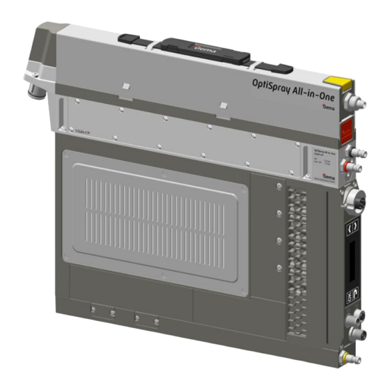
(see also in chapter "Technical data"). Fig. 1 The gun control unit will only operate in combination with the OptiGun GA04-P automatic gun or with other Gema models with a suitable diffuser (spraying air adapter). Please contact Gema if you have any further queries. -
Page 12: A Summary Of The Directives And Standards
Rev. 00 09/23 For a better understanding of the interrelationships in powder coating, it is recommended that the operating instructions for all other components be read as well, so as to be familiar with their functions too. A summary of the directives and standards This product is built according to the current state of the art. -
Page 13: Technical Data
Rev. 00 09/23 Technische Daten Technical Data Versions CAN bus OptiSpray All-in-One (CG26-CP) The equipment designation is indicated on the type plate. Connectable guns OptiSpray All-in-One (CG26-CP) connectable OptiGun type GA04-P OptiGun type GA03-P yes* OptiSelect Pro Type GM04 yes (with diffuser) OptiSelect type GM03 yes* (with diffuser) The PowerBoost functionality is not available. -
Page 14: Pneumatic Data
4 (dew point ≤ 3 °C) or Class 5 (dew point ≤ 7 °C) Residual content 0.1 mg/m³ Class Gema Switzerland GmbH recommends compressed air quality according to ISO 8573-1 class 3.4.2. Dimensions OptiSpray All-in-One (CG26-CP) Width 390 mm Depth... -
Page 15: Powder Output (Reference Values)
Rev. 00 09/23 Powder output (reference values) OptiSpray All-in-One (CG26-CP) In OptiCenter: Conveying hose till 20 m – 50-300 g/min internal Ø 7 mm Suction tube/hose up to 30 cm- internal Ø 4.5 mm In manual equipment: Conveying hose till 20 m – 50-300 g/min internal Ø... -
Page 16: Sound Pressure Level
Rev. 00 09/23 Sound pressure level OptiSpray All-in-One (CG26-CP) Normal operation < 60 dB(A) The sound pressure level was measured while the unit was in operation; measurements were taken at the most frequent operator positions and at a height of 1.7 m from the ground. The specified value is applicable only for this product itself and does not take into account external noise sources or cleaning impulses. -
Page 17: Compatibility And Interactions
Rev. 00 09/23 Compatibility and interactions The gun control is used with following types of OptiCenter: – OptiCenter All-in-One Type OC10 and OC10 Design and function Overall view Fig. 3 Operating and display Back panel with interfaces elements Application pump Housing with control Product description •... -
Page 18: Operating Elements
Rev. 00 09/23 Operating elements Display Fig. 4: Display Designation Function Display of program numbers, system parameters, error diagnosis codes, actual values, desired values – Powder output (display in %) – Total air volume (display in Nm³/h) – Electrode rinsing air (display in Nm³/h) –... - Page 19 Rev. 00 09/23 Input keys Fig. 5: Input keys Designation Function Selection key – The displayed menu can be accessed – The displayed value is activated in order to be set Back key – Return to the previous menu – Confirmation of the set value –...
-
Page 20: Menu Structure
Rev. 00 09/23 Menu structure Start display ➔ Menu level Programs System parameters Correction values Settings Application (System parameters (Correction Values) (Settings) Parameters) Powder output P00-P12 C0-C9 Rotate the display see chapter "System see chapter parameters" on page "Entering the correction values"... -
Page 21: Connections
Rev. 00 09/23 Connections Compressed air hoses / cables Fig. 6: Connections Connection Description Compressed air connection Powder hose connection Electrode rinsing air connection Mains cable connection Gun cable connection CAN bus connection (IN) CAN bus connection (OUT) Spraying air connection Product description •... -
Page 22: Scope Of Delivery
Rev. 00 09/23 Pin assignment Power IN 2.1 connection Neutral conductor (power supply) Phase (100-240 VAC) External release (100-240 VAC) – PE grounding Connection Gun 2.2 Ground INTERCOM Ground Trigger – Oscillator PE grounding Connection CAN IN 2.3 24 VDC CAN high CAN low Enclosure –... -
Page 23: Typical Properties - Characteristics Of The Functions
Rev. 00 09/23 Typical properties – Characteristics of the functions Adjustable operating mode (Program mode) In this operating mode, 250 individually definable programs (P001-P250) are available. These programs are automatically saved and can be recalled again as the application requires. fig. -
Page 24: Correction Values
0.1 – 10 million of pumping cycles Pinch valves (complete) Warning limit at 20% remaining service life Default 3.0 (changes only in consultation with Gema) 0.1 – 999 days free, e.g. filter elements No warning limit, only alarm display at the e.g. -
Page 25: Assembly / Connection
Rev. 00 09/23 Assembly / Connection Assembly guide The gun control unit is mounted into place using 2xM4 screws on the front side. Please contact Gema for other installation possibilities. Fig. 8 Assembly / Connection • 25 OptiSpray All-in-One (CG26-CP) -
Page 26: Connection Instructions
Rev. 00 09/23 Connection instructions The gun control unit is supplied ready for use by the manufacturer. Just a few cables and hoses must be connected. (See chapter "Pin assignment" on page 22.) Fig. 9: Connection instructions – overview Compressed air hose Powder pump Powder hose Control unit All-in-One... -
Page 27: Set-Up
Rev. 00 09/23 Set-up Usually, this control unit is used in automatic plants. Fig. 10: OptiSpray All-in-One in OptiCenter Assembly / Connection • 27 OptiSpray All-in-One (CG26-CP) - Page 28 Rev. 00 09/23 28 • Assembly / Connection OptiSpray All-in-One (CG26-CP)
-
Page 29: Start-Up
Rev. 00 09/23 Start-up Preparation for start-up The gun control unit always starts up to the last configured settings. Basic conditions When starting up the gun control unit, the following general conditions impacting the coating results must be taken into consideration: –... - Page 30 Rev. 00 09/23 Set the corresponding system parameter value with the key. Select parameter values according to the following table Description Values Display Application 6: Automatic device (CG26) (Device type) 0: P in = 5.5 bar Pressure 1: P in = 6 bar (Input pressure) 2: P in = 6.5 bar Air unit...
- Page 31 Rev. 00 09/23 Description Values Display 0: 20 kbit/s 1: 50 kbit/s 2: 100 kbit/s 100k 3: 125 kbit/s 125k CAN Baud rate 4: 250 kbit/s 250k 5: 500 kbit/s 500k 6: 800 kbit/s 800k 7: 1 Mbit/s CAN Node ID 1-127 0: Gun release is reset Turn gun off...
-
Page 32: Can Bus
Rev. 00 09/23 System parameter P03 (measuring unit) This parameter is used to determine the measuring unit for all airs (total air and electrode rinsing air). If the parameter is set to 1 (scfm), then all air values are shown in this measuring unit. System parameter P10 The device can export log reports of the program run to an SD card for test purposes and for finding defects. -
Page 33: Hardware
Rev. 00 09/23 Hardware The OptiSpray control units are connected to the central PLC control unit via CAN bus cables. The last bus client is fitted with a terminal plug with terminal resistor in order to terminate the network correctly. A maximum of up to 127 Control units can be operated in a network. - Page 34 Rev. 00 09/23 Baud rate – system parameter P05 P05 value Baud rate 20 kbit/s 50 kbit/s 100 kbit/s 125 kbit/s 250 kbit/s 500 kbit/s 800 kbit/s 1 Mbit/s Default value of system parameter P05 = 3 The Baud rate is selected with 125 kbits as default. This setting permits a maximum cable length of approx.
-
Page 35: Operation
Rev. 00 09/23 Operation Operation During the initial commissioning of the device, the functional check must be performed without powder! Starting the individual adjustable programs Switch on the gun control unit Program 001 active Select the desired program number (001-250) using Change the application parameters as required Programs 001-250 are preset at the factory but can be modified at any time, after which they are automatically stored. - Page 36 Rev. 00 09/23 Set the corresponding value with the key. Scroll to the next or previous parameter with the Selection is cyclical, i.e. after the last parameter, the first starts again and vice versa. Press key to quit the application parameter mode. –...
-
Page 37: Setting Powder Output And Powder Cloud
Rev. 00 09/23 Setting powder output and powder cloud The powder output depends on the selected powder output (in %), and the powder cloud on the selected total air volume. As a factory default value, a powder rate of 50% and a total air volume of 4 Nm³/h are recommended. -
Page 38: Setting The Spraying Air
Rev. 00 09/23 Setting the spraying air The spraying air (ZL) will be set in accordance to the calculated transport air (TL) and the adjusted total air volume (GL). Formula: GL = ZL + TL fig. 12: Air streams in the diffuser adapter Total air Transport air Spraying air... -
Page 39: Remote Operation
Rev. 00 09/23 Remote operation There is the possibility to remotely control the device externally via CAN- Bus. Local operation in remote operating mode In remote operating mode, local operation is limited to: – Display of the desired values of the current program –... -
Page 40: Correction Values
(e.g. the adjustment of different powder outputs in the plant). ATTENTION Incorrectly set correction values can lead to coating errors The plant was optimally set by the Gema service engineer at the first start-up. ► Changes of correction values may only be made by Gema trained personnel. -
Page 41: Daily Correction Value C2
Rev. 00 09/23 Select correction values according to the following table Default values Corr. Description Range value Standard Special 0 – 18 Minimum suction time (%) 40 – 100 Powder hose correction value (%) 50 – 150 Daily correction value (%) 0 –... -
Page 42: Checking The Software Version
Rev. 00 09/23 Checking the software version Select the submenu INFO in the MAIN MENU – The actual software version is displayed. Operating hours counter Select the submenu INFO in the MAIN MENU Press for switching to the next display –... - Page 43 Rev. 00 09/23 Press to switch to the corresponding display – All values are reset. The device must be set-up again. Operation • 43 OptiSpray All-in-One (CG26-CP)
- Page 44 Rev. 00 09/23 44 • Operation OptiSpray All-in-One (CG26-CP)
-
Page 45: Decommissioning / Storage
Rev. 00 09/23 Decommissioning / Storage Shutdown End the coating procedure Switch off the control unit The adjustments for high voltage, powder output volume and electrode rinsing air remain stored. When the product will not be used for several days Switch off the power to the control unit at the main switch Clean the gun and the components for powder conveying (see therefore the corresponding user manuals) -
Page 46: Physical Requirements
Rev. 00 09/23 Physical requirements Storage must be inside a dry building at a temperature between +5 and +50 °C. Do not expose to direct sunlight! Maintenance during storage Maintenance schedule No maintenance schedule is necessary. Maintenance works During long-term storage, periodically perform a visual check. 46 •... -
Page 47: Maintenance / Repairs
Rev. 00 09/23 Maintenance / Repairs ATTENTION Any unauthorized modifications and alterations to the product are not permitted for safety reasons and exclude the manufacturer’s liability for any resulting damage! Regular, careful cleaning and maintenance extends the service life of the product and ensures long-lasting, uniform coating quality! –... -
Page 48: Maintenance Of The Dense Phase Pump
Rev. 00 09/23 Maintenance of the dense phase pump Maintenance based on monitoring of the wear parts The powder pump indicates it is time for maintenance by changing the maintenance indicator from . If the recommended operating life is exceeded (e.g. pinch valve), the indicator changes to Icon Status Condition/Action... -
Page 49: Daily Maintenance
1 x weekly no action Pinch valves Schedule maintenance Carry out maintenance Reset service life – Pinch valve diagnosis by Gema Service OK = no action Pinch valves NOK = replace Carry out maintenance Reset service life – Filter elements... -
Page 50: Cleaning
Rev. 00 09/23 Reinigung Cleaning Cleaning the Application pump (color change) For the preparation of a color change, the pump has to be rinsed. The rinsing procedure can be started and stopped only externally via control unit or plant control. –... -
Page 51: Repair Work
Repair work In the event of malfunctions or faults, the product must be checked and repaired at an authorized Gema service location. The repairs must only be performed by an authorized specialist. Improper interventions can result in serious danger for user or the... -
Page 52: Pump Disassembly
Rev. 00 09/23 Required tools Fig. 15 Torx L-key size 20 Needle nose pliers Torx L-key size 10 Special key (for CAN bus plug) – order no. 1027 431 Open-ended wrench 14 mm ATTENTION Incorrectly assembled parts may cause malfunctions or defects ►... - Page 53 Rev. 00 09/23 Maintenance / Repairs • 53 OptiSpray All-in-One (CG26-CP)
- Page 54 Rev. 00 09/23 54 • Maintenance / Repairs OptiSpray All-in-One (CG26-CP)
- Page 55 Rev. 00 09/23 Maintenance / Repairs • 55 OptiSpray All-in-One (CG26-CP)
-
Page 56: Replacing The Pinch Valves
Rev. 00 09/23 Replacing the pinch valves 56 • Maintenance / Repairs OptiSpray All-in-One (CG26-CP) - Page 57 Rev. 00 09/23 ATTENTION Defective pinch valve causes blockage of the filter elements ► Clean or replace the corresponding filter element! Maintenance / Repairs • 57 OptiSpray All-in-One (CG26-CP)
-
Page 58: Replacing The Filter Elements
Rev. 00 09/23 Replacing the filter elements ATTENTION Use of non-permissible cleaning agents may cause damage to the plastic pinch valve body ► When cleaning the pinch valve bodies, do not use alcohol, acetone, benzol or other solvents! ► For cleaning, use benzine, light lye or acid or a cleaning agent! 58 •... - Page 59 Rev. 00 09/23 ATTENTION Incorrectly assembled parts may cause malfunctions or defects ► Reassembly is in reverse order! ► Observe the tightening torques when assembling! After installing new filter elements, an increased powder output is to be expected for a short time. Maintenance / Repairs •...
- Page 60 Rev. 00 09/23 60 • Maintenance / Repairs OptiSpray All-in-One (CG26-CP)
-
Page 61: Fault Clearance
Rev. 00 09/23 Fault clearance Error diagnosis of the software General information The correct function of the Gun control unit is constantly monitored. If the equipment software determines a fault, an error message is indicated with a help code. Following is monitored: –... - Page 62 Total air is smaller than minimum High voltage: No vibrations in the oscillator, Contact Gema Service gun error cable break, oscillator or gun is defective Cable or cascade defective. The Contact Gema Service gun error overload control unit is switched off.
- Page 63 Check cabling connections No ACK to “Boot Up No CAN node is answering to between the users, Message” received the “Boot Up Message”. otherwise contact Gema service Throttle motors: Throttle motor or needle Contact Gema Service Transport air reference jammed, limit switch defective,...
-
Page 64: Help Codes List
Rev. 00 09/23 Code Description Criteria Remedy Communication Mainboard-Gun: Communication error Gun, gun cable or Mainboard Replace or contact Gema mainboard-gun defective Service Bluetooth: Firmware Bluetooth No firmware installed on the Update the firmware of the module Bluetooth module Bluetooth module to at least V1.5.0... -
Page 65: Disposal
Requirements on personnel carrying out the work The disposal of the product is to be carried out by the owner or operator. When disposing of components that are not manufactured by Gema, the instructions in the respective manufacturer’s documentation must be observed. - Page 66 Rev. 00 09/23 66 • Disposal OptiSpray All-in-One (CG26-CP)
-
Page 67: Spare Parts List
Ø 8/6 mm, 8 mm outside diameter (o/d) / 6 mm inside diameter (i/d) WARNING Use of non-original Gema spare parts Use of Non-Gema replacement spare parts may invalidate some or all approval certificates and accreditations; and the user assumes all explosion risks associated with use of these parts. Use of these replacement spare parts may void any and all warranty claims. -
Page 68: Gun Control Unit Optispay All-In-One (Cg26-Cp)
Rev. 00 09/23 Gun control unit OptiSpay All-in-One (CG26-CP) Gun control unit OptiSpay All-in-One (CG26-CP) – complete 1024 000 Valve assembly A – complete, see corresponding spare parts list Pump body – complete, see corresponding spare parts list Valve assembly B – complete, see corresponding spare parts list Pump connection –... - Page 69 Rev. 00 09/23 Gun control unit OptiSpay All-in-One (CG26-CP) Fig. 16 Spare parts list • 69 OptiSpray All-in-One (CG26-CP)
-
Page 70: Valve Assembly A
Rev. 00 09/23 Valve assembly A Solenoid valve 1009 936 O-ring – Ø 5x1 mm 1026 914# Input filter 1023 993 O-ring – Ø 13x1.5 mm 1026 353# Coupling plug 1023 992 Coding ring – yellow 1026 338 Screw – M4x10 mm 1026 379 # Wear part Fig. -
Page 71: Enclosure
Rev. 00 09/23 Enclosure Main printed circuit board 1026 340 Throttle valve – complete 1026 940 PT-screw – 3x12 mm 1026 187 CAN bus module 1026 326 PT-screw – 2x6 mm 1026 788 Screw – M4x20 mm 1026 371 Gun connection 1026 751 Display module –... -
Page 72: Valve Assembly B
Rev. 00 09/23 Valve assembly B Solenoid valve – complete 1023 975 Gasket 1026 776 O-ring – Ø 12x1.5 mm 1026 375 # Screw – M4x10 mm 1026 379 Gasket 1026 319 Screw-in connector 1026 395 O-ring – Ø 5x1 mm 1026 914# Filter 1025 689... -
Page 73: Quick Change System
Rev. 00 09/23 Quick change system Screw – M4x30 mm 1026 372 Powder stop filter 1023 230 Fig. 20: Spare parts list • 73 OptiSpray All-in-One (CG26-CP) -
Page 74: Pump Head
Rev. 00 09/23 Pump head Cover 1023 796 Screw – M4x10 mm 1026 371 Suction elbow – complete (incl. pos. 4 and 5) 1026 791 O-ring – Ø 11x1.5 mm 1026 915 # O-ring – Ø 15x1.5 mm 1026 356 # Suction module housing O-ring –... -
Page 75: Index
Rev. 00 09/23 Index About these instructions ........7 Intended use ............ 11 Assembly ............25 Maintenance ............ 47 Basic safety instructions ........9 Maintenance during storage ......46 Maintenance of the dense phase pump ..48 Cleaning ............50 Color change ............ - Page 76 Rev. 00 09/23 Safety symbols ..........7 Service kit (Pump head) ........51 Typical characteristics ........23 Shutdown ............45 Sound pressure level ........16 Spare parts list ..........67 Standards, European ........12 Versions ............13 Start-up ............29 Storage ............
- Page 78 Rev. 00...
Need help?
Do you have a question about the OptiSpray All-in-One CG26-CP and is the answer not in the manual?
Questions and answers