
Subscribe to Our Youtube Channel
Related Manuals for Gema OptiStar CG08-C


Summary of Contents for Gema OptiStar CG08-C
- Page 1 1010 771 Operating instructions and spare parts list OptiStar CG08(-C) Gun control unit Translation of the original operating instructions...
- Page 2 To the best of our knowledge and belief, the information contained in this publication was correct and valid on the date of publication. Gema Switzerland GmbH makes no representations or warranties with respect to the contents or use of this publication, and reserves the right to revise this publication and make changes to its content without prior notice.
-
Page 3: Table Of Contents
V 02/18 Table of contents General safety regulations Safety symbols (pictograms) ................... 3 Proper use ....................... 3 Product-specific safety measures ................4 OptiStar CG08 Gun control unit ..............4 About this manual General information ....................5 Software version ..................... 5 Product description Field of application .................... - Page 4 V 02/18 Select predefined operating mode (Preset mode) ........31 Starting the user-defined operating mode (Program mode) ....31 Setting powder output and powder cloud ..........32 Setting the electrode rinsing air ............... 33 Correction values ....................33 Entering the correction values ..............33 Powder output/powder hose correction ...........
-
Page 5: General Safety Regulations
OptiStar CG08(-C) is put into operation. Safety symbols (pictograms) The following warnings with their meanings can be found in the Gema Switzerland operating instructions. The general safety precautions must also be followed as well as the regulations in the operating instructions. -
Page 6: Product-Specific Safety Measures
If it is to be used in a manner outside the scope of the safety concept, then corresponding measures must be taken. NOTE: For further security information, see the more detailed Gema safety regulations! 4 • General safety regulations OptiStar CG08(-C) -
Page 7: About This Manual
V 02/18 About this manual General information This operating manual contains all the important information you require for the working with the OptiStar CG08(-C) Gun control unit. It will safely guide you through the start-up process and give you references and tips for the optimal use of your new powder coating system. -
Page 9: Product Description
Product description Field of application The OptiStar CG08(-C) Gun control unit is designed exclusively for controlling the Gema powder coating guns (see also in chapter "Technical data"). Any other use is considered non-compliant. The manufacturer is not responsible for any incorrect use and the risks associated with such... -
Page 10: Technical Data
V 02/18 Technical data OptiStar CG08 - versions OptiStar CAN bus CG08 CG08-C The equipment designation is indicated on the type plate. Connectable guns OptiStar CG08(-C) connectable OptiGun GA03 WARNING: The OptiStar CG08(-C) gun control unit may only be used with the specified gun types! Electrical data OptiStar CG08(-C) -
Page 11: Pneumatic Data
V 02/18 Pneumatic data OptiStar CG08(-C) Compressed air connection Quick coupling 5.5 bar Input pressure (must be set in the system 6.0 bar parameter P2) 6.5 bar Max. input pressure 10 bar / 145 psi Min. input pressure (while unit in operation) 5.5 bar / 80 psi Max. -
Page 12: Air Flow Rates
V 02/18 Air flow rates The total air consists of conveying air and supplementary air, in relation to the selected powder quantity (in %). As a result the total air volume is maintained constant. OptiStar CG08(-C) Conveying air flow rate 0-5.4 Nm³/h Supplementary air flow rate 0-4.5 Nm³/h... -
Page 13: Design And Function
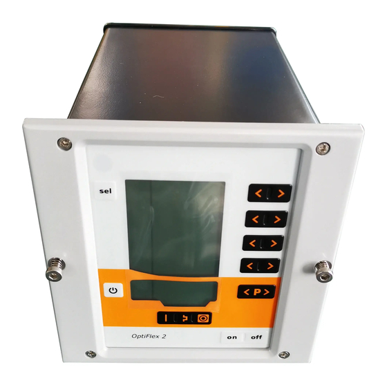
V 02/18 Design and function General view 1 Front plate with control and 3 Back panel with interfaces display elements 2 Enclosure Product description • 11 OptiStar CG08(-C) -
Page 14: Operating Elements
V 02/18 Operating elements Display and input buttons NOTE: For easier operation of the control unit, the preset and actual values are distributed across several levels. The "sel" key is used to switch between the levels. If no controls are used within 6 s, the device automatically returns to level 1. - Page 15 V 02/18 Displays and LEDs, Level 2 Designation Function Electrode rinsing air (display in Nm³/h) Display illumination (0-8) Product description • 13 OptiStar CG08(-C)
-
Page 16: Input Keys And Switches
V 02/18 Input keys and switches T1 / T2 T3 / T4 T5 / T6 T7 / T8 T10/T11 T16/T17 Input keys and switches Designation Function Input keys for desired values and system parameters T1-T8 Switch between display levels T9 (Select) Program change T10-T11 Gun release... -
Page 17: Connections
V 02/18 Connections Compressed air hoses / cables OptiStar CG08-C – Connections - Compressed air hoses / cables Connection Description Compressed air connection 1.1 Main air IN Mains cable connection 2.1 Power IN Gun cable connection 2.2 Gun CAN bus connection (IN) 2.3 Aux... -
Page 18: Pin Assignment
V 02/18 Pin assignment Power IN connection Neutral conductor (power supply) Phase (100-240 VAC) System input ON/OFF (100-240 VAC) Grounding PE Gun connection Ground Remote control 1 (GM03) Ground Trigger Remote control 2 (GM03) Oscillator Grounding PE CG08-C pin assignment CAN IN plug with 4 pins (2.3 Aux) Ground 24 VDC... -
Page 19: Typical Properties - Characteristics Of The Functions
V 02/18 Typical properties – Characteristics of the functions Operating modes The OptiStar CG08(-C) gun control unit has two operating modes. Predefined operating mode (Preset mode) The OptiStar CG08(-C) gun control unit has three preset application modes: Application mode for flat parts This application mode is suitable for the coating of simple, flat workpieces without larger cavities. -
Page 20: Rinsing Mode
V 02/18 Precise Control of spraying Current (PCC Mode) For coating components with both complex and simple geometries, a spraying current of below 10 µA can be selected to prevent unintended overcoating on the simpler surfaces. This is especially important in combination with high loading powders (such as metallic). -
Page 21: Monitoring Of Wearing Parts
V 02/18 Monitoring of wearing parts Wearing parts have a limited service life. The OptiStar CG08(-C) gun control unit offers functionality to monitor the service life of up to four wearing parts using a reverse counter: NOTE: The order of wearing parts to be monitored as well as the service life can be set as needed by the operator. -
Page 22: Keyboard Lock
V 02/18 Keyboard lock The OptiStar CG08(-C) gun control unit has a keyboard lock to prevent modification of individual parameter values kV, µA etc.) within the operating modes (Program and Preset). Following is not affected by the keyboard lock: Program selection Display of desired values of the current program Displaying the actual values Error acknowledgement... -
Page 23: Correction Factor For The Powder Output
V 02/18 Correction factor for the powder output The OptiStar CG08(-C) gun control unit enables a zeroing out of the powder output. This allows for compensation to different powder hose lengths connecting to the pistol. The correction factor C0 can be selected such that no powder is output when the powder share is reduced to 0%. -
Page 25: Commissioning
V 02/18 Commissioning Preparation for start-up Basic conditions When starting up the OptiStar CG08(-C) gun control unit, the following general conditions impacting the coating results must be taken into consideration: Gun control unit correctly connected Gun correctly connected Corresponding power and compressed air supply available Powder preparation and powder quality Mounting instructions The OptiStar CG08(-C) gun control unit is mounted into place using 2xM6... -
Page 26: Connection Instructions
V 02/18 Connection instructions Maintenance unit 5.5 bar 6.0 bar 6.5 bar Injector Connection instructions - overview NOTE: Use clamp to connect grounding cable to the cabin or the suspension arrangement. Check ground connections with Ohm meter and ensure 1 MOhm or less! 24 •... - Page 27 V 02/18 NOTE: The compressed air must be free of oil and water! Commissioning • 25 OptiStar CG08(-C)
-
Page 29: Initial Start-Up
V 02/18 Initial start-up NOTE: The gun control unit always starts up to the last configured settings. System parameters The OptiStar CG08(-C) Gun control unit is configured by using the system parameters. This configuration will be saved in the equipment memory. - Page 30 V 02/18 6. Select parameter values according to the following table Values Display Description Fluidizing device Type F (CG13) Box device with vibrator Type B (CG13) Stirrer device Type S (CG13) Device type Automatic device (CG08/C) Manual device with S Fd fluidization (CG13) Application pump (CG11-P)
- Page 31 V 02/18 System parameter P00 If the OptiStar CG08(-C) gun control unit is equipped with the CAN bus- option, this device type is recognized automatically. The system parameter P00 is set to 3 when device is starting. NOTE: A wrong parameterization leads to various malfunctions! ►...
- Page 32 V 02/18 System parameter P10 The device can export log reports of the program run to an SD card for test purposes and for finding defects. If an SD card is inserted during the switching on procedure, the log messages are also recorded onto the SD card. The data are record in the MESSAGES.LOG file in the root directory.
-
Page 33: Operation
V 02/18 Operation NOTE: During the initial commissioning of the device, it is recommended that the functional check be performed without powder! Select predefined operating mode (Preset mode) 1. Turn on the gun control unit with the ON key 2. Press the corresponding application key the arrow above the pressed key is switched on The pre-defined application modes have preset values for high voltage and spray current:... -
Page 34: Setting Powder Output And Powder Cloud
V 02/18 Description Presetting Powder output Total air 0 Nm³/h High voltage 0 kV Spray current 0 µA 0.1 Nm³/h Electrode rinsing air Setting powder output and powder cloud The powder output depends on the selected powder output (in %) and the selected total air volume. -
Page 35: Setting The Electrode Rinsing Air
V 02/18 Setting the electrode rinsing air Press the key T9 (SELECT) The second display level will be shown Adjust the correct electrode rinsing air according to the applied nozzles (deflector plate, flat jet nozzle) NOTE: By using flat jet nozzles, the factory default value is approx. 0.3 Nm³/h, by using round jet nozzles with air-rinsed deflector plates, the factory default value is approx. -
Page 36: Powder Output/Powder Hose Correction
V 02/18 T1 / T2 T3 / T4 3. The correction factor number is shown in the display A1 with a C placed in front 4. Set the corresponding correction value with the T3 or T4 key. The value of the adjusted correction factor appears on corresponding display A2 5. - Page 37 V 02/18 2. To enter the system parameter mode, press the key T12 longer than 5 seconds. 3. Press The display switches to the correction factors level: The correction factor number is shown in the display A1 with a C placed in front 4.
-
Page 38: Correction Factor - Diagram
V 02/18 Example table for powder output/powder hose correction Powder output correction C0 before after correction correction C0=1.8 Nm³/h 20 gr. 12 gr. C0=1.7 Nm³/h C0=1.8 Nm³/h 10 gr. 13 gr. C0=1.8 Nm³/h C0=1.8 Nm³/h 0 gr. 12 gr. C0=2.6 Nm³/h etc. -
Page 39: Cleaning Mode
V 02/18 Cleaning mode The cleaning mode enables blowing off powder accumulations in the powder hose with preset air pressure. This function is a two steps process to activate. The powder hose cleaning mode can be activated also by an optional bus connection such as CAN bus. -
Page 40: Monitoring Of Wearing Parts And Trigger Counter
V 02/18 if no operation is started within 15 s (not in Remote operation mode) if the cleaning sequence has finished The active cleaning function is terminated immediately when exiting this mode. The cleaning mode is terminated by pressing the key. -
Page 41: View Remaining Service Life
V 02/18 View remaining service life 1. Press key 2x The display switches to the wearing part monitoring level Display of remaining service life: range 0.1 – 500 days < or > adjustment of service life Quit wearing parts monitoring <... -
Page 42: Deactivation Of Wearing Part Monitoring
V 02/18 Deactivation of wearing part monitoring 1. Press key simultaneously Monitoring is deactivated. Setting the background illumination 1. Press The display switches to the following level: Select the desired brightness 40 • Initial start-up OptiStar CG08(-C) -
Page 43: Activate/Deactivate The Keyboard Lock
V 02/18 Activate/deactivate the keyboard lock 1. Hold key pressed 2. Press The keyboard lock is activated. The remote display blinks. 3. The keyboard lock is cancelled by pressing the same key combination Checking the software version 4. Press these two keys at the same time The status display is shown as long as the keys are held. -
Page 44: Shutdown
V 02/18 6. All values are reset. The control unit must be set-up again. Shutdown 1. Release gun trigger 2. Switch off the control unit NOTE: The adjustments for high voltage, powder output volume and electrode rinsing air remain stored If in disuse for several days 1. -
Page 45: Can Bus
V 02/18 CAN bus The OptiStar CG08-C Gun control unit, fitted with a CAN bus interface, is a simple CANopen slave. It operates in a network with a central control unit (Master). Communication takes place exclusively between the Master and the Slaves. -
Page 46: Can Bus Cable - Plug Assignment
V 02/18 OptiStar no. 1 OptiStar no. 2 OptiStar no. 127 (max.) PLC control with Terminal resistor CAN bus CAN bus - connections CAN bus cable - plug assignment Signal Color white +24 VDC black CAN H black CAN L black CAN bus cable System release in network operation... -
Page 47: Determining User Address (Node-Id) And Baud Rate
V 02/18 Determining user address (Node-ID) and Baud rate Each OptiStar Gun control unit, which operates in the CAN network, must have assigned an individual user address (Node-ID). The Baud rate setting enables the transmission speed setting. The Baud rate value can be set by editing the system parameter P05, and the Node ID value can be set by editing the system parameter P06. -
Page 49: Fault Remedying
Code Description Criteria Remedy Pneumatics: Solenoid coil current lower than contact Gema Service preset limiting value Trigger valve Valve defective, main board or cable defective Supplementary air flow too The preset value for supplementary Lower supplementary air value... - Page 50 Total air is smaller than minimum High voltage: No vibrations in the oscillator, cable contact Gema Service Gun error break, oscillator or gun is defective Offset spray current Grounded current measurement contact Gema Service...
-
Page 51: Help Codes List
Communication Mainboard-Gun: Communication error Mainboard defective contact Gema Service Mainboard Communication error Gun, gun cable or Mainboard Replace or contact Gema Mainboard-Gun defective Service Communication error Mainboard defective contact Gema Service Mainboard Help codes list The last appeared four errors are stored in a list by the software. If an error appears, which is already in the list, he will not be listed again. -
Page 53: Spare Parts List
Ø 8/6 mm, 8 mm outside diameter (o/d) / 6 mm inside diameter (i/d) WARNING! Only original Gema spare parts should be used, because the explosion protection will also be preserved that way. The use of spare parts from other manufacturers will invalidate the Gema guarantee conditions! Spare parts list •... -
Page 54: Optistar Cg08(-C) Gun Control Unit
V 02/18 OptiStar CG08(-C) Gun control unit 1009 299 OptiStar CG08 Gun control unit – complete 1009 300 OptiStar CG08-C Gun control unit – complete Cover 1008 301 OptiStar CG08(-C) Gun control unit 52 • Spare parts list OptiStar CG08(-C) -
Page 55: Optistar Cg08(-C) - Front Plate And Power Pack
V 02/18 OptiStar CG08(-C) – Front plate and power pack Front plate - complete (pos. 1-12) 1009 860 Front plate with foil keyboard (pos. 5-8) 1009 859 OptiStar Mainboard V2.0 - complete 1009 844 Spacer sleeve - Ø 3.1/6x15 mm PCB Powerboard V2.0 1009 865 Spacer sleeve - Ø... -
Page 56: Optistar Cg08(-C) - Inside Rear Wall
1000 064 Plastic tube - Ø 8/6 mm 103 152* Fluidizing pad - 1/8"a 237 264 Cap screw - M4x16 mm 216 801 * Please indicate length OptiStar CG08-C – inside rear wall 54 • Spare parts list OptiStar CG08(-C) -
Page 57: Optistar Cg08(-C) Connections
388 530 CAN bus cable – 6.0 m (CG08-C only) Bus terminal resistor (not shown) (CG08-C only) 387 606 Mains cable – 4.5 m 1002 563 * Please indicate length OptiStar CG08-C connections Spare parts list • 55 OptiStar CG08(-C)
Need help?
Do you have a question about the OptiStar CG08-C and is the answer not in the manual?
Questions and answers