
Subscribe to Our Youtube Channel
Related Manuals for Gema OptiStar 4.0


Summary of Contents for Gema OptiStar 4.0
- Page 1 Rev. 00 1011 532 Operating instructions and Spare parts list Gun control unit OptiStar 4.0 (CG24-CP) Translation of the original operating instructions...
- Page 2 To the best of our knowledge and belief, the information contained in this publication was correct and valid on the date of publication. Gema Switzerland GmbH makes no representations or warranties with respect to the contents or use of this publication, and reserves the right to revise this publication and make changes to its content without prior notice.
-
Page 3: Table Of Contents
Connections ..................... 20 Scope of delivery ....................22 Typical properties – Characteristics of the functions ..........22 Operating modes ..................22 Communication with the Gema electrostatic app ........24 Cleaning mode ..................25 Background illumination ................26 Correction values ..................26 Assembly / Connection Assembly guide ..................... - Page 4 General information ................. 57 Help codes ....................57 Help codes list ..................60 Appearance of errors ................60 Disposal Introduction ......................61 Requirements on personnel carrying out the work ........61 Disposal regulations ................61 4 Table of contents OptiStar 4.0 (CG24-CP)
- Page 5 OptiStar CG24-CP Gun control unit ..............64 Front plate and power pack .................. 65 Inside back plate ....................66 Inside back plate ....................67 Connecting material ....................68 Connecting material ....................69 Table of contents 5 OptiStar 4.0 (CG24-CP)
-
Page 7: About These Instructions
General information This operating manual contains all important information which you require for the working with the OptiStar 4.0 (CG24-CP). It will safely guide you through the start-up process and give you references and tips for the optimal use when working with your powder coating system. -
Page 8: Structure Of Safety Notes
Possible consequences of the danger ► Prevention of the danger Software version This document describes the operation of the control unit OptiStar 4.0 (CG24-CP) with software version starting from 0.24.00. See chapter "Checking the software version" on page 51. Presentation of the contents Figure references in the text Figure references are used as cross references in the descriptive text. -
Page 9: Safety
If this product is to be used for other purposes or other substances outside of our guidelines then Gema Switzerland GmbH should be consulted. - Page 10 ► Before working with the device, organize the required documents and read the section "Safety regulations". ► Work should only be carried out in accordance with the instructions of the relevant documents. ► Always work with the complete original document. 10 Safety OptiStar 4.0 (CG24-CP)
-
Page 11: Product Description
Rev. 00 03/19 Product description Intended use The Gun control unit is designed exclusively for controlling the Gema powder coating guns and the OptiSpray AP01 application pump (see also in chapter "Technical data"). Fig. 1 Up to 2 Application pumps can be controlled by this control unit: –... -
Page 12: A Summary Of The Directives And Standards
Coating plants – spray booths for application of EN 12981 organic powder coating material - Safety requirements Recognized safety-related regulations Electrostatic coating 764 / DGUV Information Trade Union information concerning health and 209-052 safety during work (BGI) 12 Product description OptiStar 4.0 (CG24-CP) -
Page 13: Reasonably Foreseeable Misuse
Nominal output voltage (to the 12 V gun) Nominal output current (to the 1.2 A gun) Protection type IP54 Max. surface temperature 85 °C (+185 °F) 0102 II 3 (2) D Approvals PTB17 ATEX 5002 Product description 13 OptiStar 4.0 (CG24-CP) -
Page 14: Pneumatic Data
Electrode rinsing air flow rate 0-3.0 Nm³/h The total air consumption for the device is determined based on the configured air values. – These values apply for an internal control pressure of 6.0 bar! 14 Product description OptiStar 4.0 (CG24-CP) -
Page 15: Environmental Conditions
Rev. 00 03/19 Environmental conditions OptiStar 4.0 (CG24-CP) Utilization in the interior Height up to 2 000 m +5 °C - +40 °C Temperature range (+41 °F - +104 °F) Max. surface temperature +85 °C (+185 °F) 80 % for temperatures to 31 °C,... -
Page 16: Design And Function
Rev. 00 03/19 Design and function Overall view Fig. 3 Front plate with control and Back panel with interfaces display elements Enclosure 16 Product description OptiStar 4.0 (CG24-CP) -
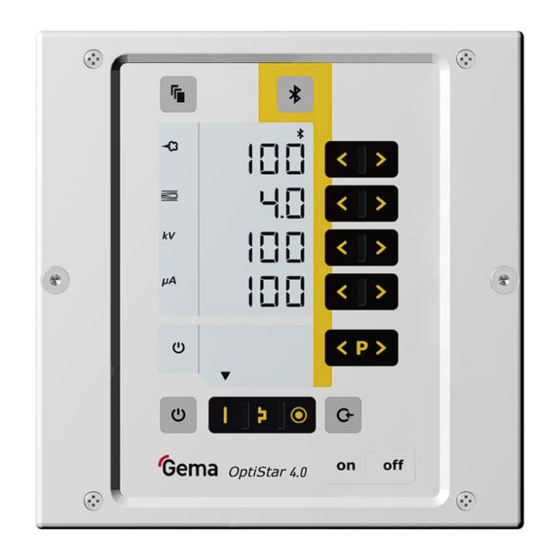
Page 17: Operating Elements
Display of predefined operating modes or display of cleaning mode during cleaning – Display of readiness for pairing the Bluetooth module with a mobile device (green) – Display of an active connection (blue) Product description 17 OptiStar 4.0 (CG24-CP) - Page 18 Rev. 00 03/19 fig. 5: Displays and LEDs, Level 2 Designation Function Electrode rinsing air (display in Nm³/h) Display background illumination (0-8) 18 Product description OptiStar 4.0 (CG24-CP)
- Page 19 Activation of the pairing readiness from the Bluetooth module to the mobile device (press for at least 2 seconds) – Display of the ID number (press for a short time) Activating the cleaning function Product description 19 OptiStar 4.0 (CG24-CP)
-
Page 20: Connections
CAN bus connection (OUT) 2.5 Ext. AP01 Application pump no. 1 connection 2.6 Ext. AP01 Application pump no. 2 connection Transport air connection Spraying air connection Electrode rinsing air connection Pinch valve air connection Grounding connection 20 Product description OptiStar 4.0 (CG24-CP) - Page 21 CAN OUT socket with 4 pins (2.4 Aux) Ground 24 VDC CAN high CAN low Enclosure – shield Connection Application pump 1 (2.5) and 2 (2.6) Control signal +24 VDC Body – grounding PE Product description 21 OptiStar 4.0 (CG24-CP)
-
Page 22: Scope Of Delivery
This application mode is suitable for the overcoating of workpieces which are already coated. In this operating modes, current (µA) and high voltage (kV) are preset, while powder and air volumes can be set and stored for each application mode. 22 Product description OptiStar 4.0 (CG24-CP) - Page 23 (such as metallic). The controller automatically switches into "PCC mode". This allows for very fast yet highly precise control. The high voltage and spray current values and their symbols are depicted in red: Fig. 10: PCC mode Product description 23 OptiStar 4.0 (CG24-CP)
-
Page 24: Communication With The Gema Electrostatic App
Rev. 00 03/19 Communication with the Gema electrostatic app The control unit is prepared for communication* with the Gema electrostatic app. The electrostatic app is optimized for mobile devices with a screen diagonal up to 15 cm (6"). The app enables customers to improve their productivity by providing the... -
Page 25: Cleaning Mode
The cleaning mode is signalized by a circling LCD segment on the display: Fig. 11: Cleaning mode The actual cleaning procedure is started and stopped by the superordinated control unit. Once the cleaning mode is quit, the unit automatically returns to the last program. Product description 25 OptiStar 4.0 (CG24-CP) -
Page 26: Background Illumination
The Gun control unit can be adapted with the correction values optimally to local conditions (e.g. the adjustment of different powder outputs in the plant). See chapter "Entering the correction values" on page 48. 26 Product description OptiStar 4.0 (CG24-CP) -
Page 27: Assembly / Connection
Rev. 00 03/19 Assembly / Connection Assembly guide The gun control unit is mounted into place using 2xM6 screws on the front side. Please contact Gema for other installation possibilities. Fig. 13 Assembly / Connection 27 OptiStar 4.0 (CG24-CP) -
Page 28: Connection Instructions
Gun cable Gun control Pinch valve air 10 Compressed air hose 11 Hose coupling Ø 8/6 – Spraying air hose Ø 6/4 mm Transport air hose 12 Powder hopper Control signal cable 28 Assembly / Connection OptiStar 4.0 (CG24-CP) - Page 29 Check ground connections with Ohm meter and ensure 1 MOhm or less. The compressed air must be free of oil and water! Close the unused connections with the provided dust protection caps! Assembly / Connection 29 OptiStar 4.0 (CG24-CP)
- Page 30 Rev. 00 03/19 30 Assembly / Connection OptiStar 4.0 (CG24-CP)
-
Page 31: Start-Up
(CAN). Entering the system parameters Turn on the gun control unit with the ON key Hold key down for 5 seconds – The display switches to the following level: Start-up 31 OptiStar 4.0 (CG24-CP) - Page 32 6: Application pump + CAN bus (CG24-CP) 0: P in = 5.5 bar Inlet pressure 1: P in = 6 bar 2: P in = 6.5 bar Unit of 0: Nm³/h measurement 1: scfm (air) 32 Start-up OptiStar 4.0 (CG24-CP)
- Page 33 2: Powder output +/- PowerBoost (Activation) is not overwritten, if a Memory Reset is performed Default values are marked by bold print. Press key to quit the system parameter mode. The display switches to the standard level Start-up 33 OptiStar 4.0 (CG24-CP)
- Page 34 This parameter is used to determine the measuring unit for all airs (total air and electrode rinsing air). If the parameter is set to 1 (scfm), then all air values are shown in this measuring unit. These lines are displayed in blue. 34 Start-up OptiStar 4.0 (CG24-CP)
- Page 35 32 MB, it is renamed as MESSAGES.1 and a new MESSAGES.LOG file is then created. Parameter Level of detail of reports value no messages few details all messages Real time timings can be impaired from a level of detail of 4. Start-up 35 OptiStar 4.0 (CG24-CP)
- Page 36 The Bluetooth ID number is determined with this parameter. An individual Bluetooth ID number must be assigned to each pistol control unit that is to be accessed via the Gema electrostatic app. This value is set to 0 in network operation.
-
Page 37: Can Bus
All actual values (process data) – All control values – All system parameters (except Baud rate and CAN address) – All error messages – All special parameters such as software version, daily correction, powder output correction etc. Start-up 37 OptiStar 4.0 (CG24-CP) -
Page 38: Hardware
19: CAN bus – connections PLC control with CAN bus Terminal resistor CAN bus cable – plug assignment fig. 20: CAN bus cable Signal Color white +24 VDC black CAN H black CAN L black 38 Start-up OptiStar 4.0 (CG24-CP) -
Page 39: Determining User Address (Node-Id) And Baud Rate
The Baud rate is selected with 125 kbits as default. This setting permits a maximum cable length of approx. 500 m from the first to the last CAN bus client. If longer cables are used, select a lower Baud rate. Start-up 39 OptiStar 4.0 (CG24-CP) - Page 40 Rev. 00 03/19 40 Start-up OptiStar 4.0 (CG24-CP)
-
Page 41: Operation
Application mode Preset kV Preset µA flat parts complicated parts overcoat The air values for total air, powder output and electrode rinsing air can be individually defined and are saved in the programs. Operation 41 OptiStar 4.0 (CG24-CP) -
Page 42: Starting The Individual Adjustable Programs
Setting the total air volume Adjust the total air volume on the gun control unit with the T3/T4 keys – Adjust the total air volume according to the corresponding coating requests 42 Operation OptiStar 4.0 (CG24-CP) - Page 43 To achieve maximum efficiency, we recommend avoided an overly high powder volume where possible! Check fluidization of the powder in the powder container Point the gun into the booth, switch the gun on and visually check the powder output Operation 43 OptiStar 4.0 (CG24-CP)
-
Page 44: Setting The Spraying Air
(deflector plate, flat jet nozzle) ≈ 0.1 Nm³/h ≈ 0.5 Nm³/h too much electrode rinsing air If in this display level is no operation for 3 seconds, the first display level is switched over independently. 44 Operation OptiStar 4.0 (CG24-CP) -
Page 45: Pinch Valves And System Backpressure Monitoring Display
Unit Current pinch valves pressure Opening time of control solenoid valve for pinch valves pressure (leak- tightness control) System backpressure 1 System backpressure 2 Press key 1x The display switches to the following level: Operation 45 OptiStar 4.0 (CG24-CP) -
Page 46: Remote Operation
During transfer from local to remote operating, and vice versa, the powder output will cease, so that the device is in a defined mode after transfer. – Remote operating mode is signaled by the symbol S12 (remote). 46 Operation OptiStar 4.0 (CG24-CP) -
Page 47: System Release In Network Operation
Designation Trigger Gun connected External release Release on mains plug System System Gun release on control unit enable logic release Gun release Command via Remote Interface Error lock Device error System lock Parameter input Operation 47 OptiStar 4.0 (CG24-CP) -
Page 48: Correction Values
ATTENTION Incorrectly set correction values can lead to damage to the Application pump The plant was optimally set by the Gema service engineer at the first start-up. ► Changes of correction values may only be made by Gema trained personnel. - Page 49 (mbar/bar) = Threshold value for error message The adjustment range applies to the half cycle time. Depending on the unit set, airflows are displayed and entered in Nm³/h or scfm. Do not change! Use only if blockings occur. Operation 49 OptiStar 4.0 (CG24-CP)
-
Page 50: Cleaning Mode
The cleaning mode can only be activated from standby mode (main menu display, no powder conveying). The prerequisite is, that all necessary release signals are present. Setting the background illumination Press the The display switches to the following level: Select the desired brightness 50 Operation OptiStar 4.0 (CG24-CP) -
Page 51: Checking The Software Version
By resetting the RAM, all user-made settings will be set to factory default! Switch off the device Press the key and hold it Switch on the control unit, the CLR display blinks Wait for approximately 5 seconds until CLR disappears Operation 51 OptiStar 4.0 (CG24-CP) - Page 52 Rev. 00 03/19 Release the – All values are reset. The control unit must be set-up again. 52 Operation OptiStar 4.0 (CG24-CP)
-
Page 53: Decommissioning / Storage
If the physical conditions are maintained, the unit can be stored indefinitely. Space requirements The space requirements correspond to the size of the product. There are no special requirements concerning distance to neighboring equipment. Decommissioning / Storage 53 OptiStar 4.0 (CG24-CP) -
Page 54: Physical Requirements
Storage must be inside a dry building at a temperature between +5 and +50 °C. Do not expose to direct sunlight! Maintenance during storage Maintenance schedule No maintenance schedule is necessary. Maintenance works During long-term storage, periodically perform a visual check. 54 Decommissioning / Storage OptiStar 4.0 (CG24-CP) -
Page 55: Maintenance / Repairs
Repair work In the event of malfunctions or faults, the product must be checked and repaired by an authorized Gema service workshop. The repairs must only be performed by an authorized specialist. Improper tampering can result in serious danger for user and equipment. - Page 56 Rev. 00 03/19 56 Maintenance / Repairs OptiStar 4.0 (CG24-CP)
-
Page 57: Fault Clearance
Here is a list of all possible help codes for this Gun control unit: Code Description Criteria Remedy Pneumatics: Solenoid coil current lower than Contact a Gema service preset limiting value center Trigger valve Valve defective, main board or cable defective Fault clearance 57... - Page 58 Total air is smaller than minimum High voltage: No vibrations in the oscillator, Contact a Gema service Gun error cable break, oscillator or gun is center defective Cable or cascade defective. The...
- Page 59 Rev. 00 03/19 Code Description Criteria Remedy High error rate when The CAN controller changes into Contact a Gema service transmitting/receiving ERROR_PASSIVE condition center The message to be received has Contact a Gema service Overflow on data no more place in the receiver...
-
Page 60: Help Codes List
AP01 pressure control supply, otherwise contact a value longer than 5 s. Gema service center AP01 pressure A/D converter timeout. Possible Contact a Gema service measurement cause: Hardware defective center The unit is configured as pump Check System parameter No AP01 interface... -
Page 61: Disposal
Requirements on personnel carrying out the work The disposal of the product is to be carried out by the owner or operator. When disposing of components that are not manufactured by Gema, the instructions in the respective manufacturer’s documentation must be observed. - Page 62 Rev. 00 03/19 62 Disposal OptiStar 4.0 (CG24-CP)
-
Page 63: Spare Parts List
When using the spare parts from other manufacturers the explosion protection is no longer guaranteed. If any damage is caused by this use all guarantee claims become invalid! ► Only original Gema spare parts should be used! Spare parts list 63 OptiStar 4.0 (CG24-CP) -
Page 64: Optistar Cg24-Cp Gun Control Unit
OptiStar CG24-CP gun control unit – complete, without item 4 1015 205 Front plate – complete, see corresponding spare parts list Enclosure Backplate – complete, see corresponding spare parts list Fig. 22 64 Spare parts list OptiStar 4.0 (CG24-CP) -
Page 65: Front Plate And Power Pack
Membrane keypad with carrier plate 1015 217 Spacer sleeve – Ø 3.6/7x5 mm Display 1015 220 Washer – Ø 3.2/7x0.5 mm Locknut – M3 Power pack – 24 VDC 1009 849 Fig. 23 Spare parts list 65 OptiStar 4.0 (CG24-CP) -
Page 66: Inside Back Plate
Connector 1009 939 Elbow joint – M5-Ø 6 mm 1009 941 AP01 interface – complete (incl. pressure sensors) 1016 132 Plastic tube – Ø 6/4 mm 103 144* * Please indicate length 66 Spare parts list OptiStar 4.0 (CG24-CP) -
Page 67: Inside Back Plate
Rev. 00 03/19 Inside back plate Fig. 24 Spare parts list 67 OptiStar 4.0 (CG24-CP) -
Page 68: Connecting Material
Connecting cable – 12 pins, 10 m 1000 976 Connecting cable – 12 pins, 15 m 1000 977 Connecting cable – 12 pins, 20 m 1000 978 Mains cable – 4.5 m 1002 563 * Please indicate length 68 Spare parts list OptiStar 4.0 (CG24-CP) -
Page 69: Connecting Material
Rev. 00 03/19 Connecting material Fig. 25 Spare parts list 69 OptiStar 4.0 (CG24-CP) - Page 71 Spare parts list ..........63 Standards, European ........12 Start-up ............31 Guidelines, European ........12 Storage ............53 Storage conditions ........... 53 Input keys and switches ........19 Typical characteristics ........22 Maintenance ............. 55 Index 71 OptiStar 4.0 (CG24-CP)
- Page 72 Rev. 00...
Need help?
Do you have a question about the OptiStar 4.0 and is the answer not in the manual?
Questions and answers