Table of Contents
Advertisement
Quick Links
Advertisement
Table of Contents

Related Manuals for Kinetico KPRO COMPACT


Summary of Contents for Kinetico KPRO COMPACT
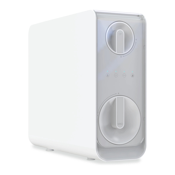
- Page 1 RO KPRO COMPACT DIRECT FLOW MANUAL...
- Page 2 INDEX User manual Technical manual Technical data sheet 9-15 Spare Parts list...
-
Page 3: Prior Warnings
USER MANUAL 1. INTRODUCTION the functionality and status indications, as well as the different security systems. Congratulations. You have acquired excellent equip- The equipment’s technical data sheet describes the ment for commercial HORECA Use. states in which the system can be found and the infor- mation provided by it. -
Page 4: Troubleshooting
5. TROUBLESHOOTING TROUBLE POSIBLE CAUSE SOLUTION 1. Leak to the outside the • Several possible causes. • Call for service. equipment. 2. Zero production. • There is no water supply. • Wait for the supply to return. • There is no power supply. •... -
Page 5: Main Features
TECHNICAL MANUAL 1. MAIN FEATURES Water treatment Reverse osmosis for Commercial Use (HORECA) Modifications for reduction or contribution -Water treatment by reverse osmosis is capable of reducing concentrations of salts and other substances in high percentages. -Minimal reduction * of certain compounds and parameters: Sodium: 85%. -
Page 6: Commissioning And Maintenance
In case the water to be treated contains: ATTENTION: The equipment must not be installed • High concentrations of iron and manganese (Greater next to a heat source or directly receiving a flow of than 1ppm measured in the rejection of the machine). • hotairover it . -
Page 7: Filter Installation
an adjoining piece of furniture. Install the production outlet, drain collar and inlet adapter and connect them to the respective equipment connectors (6 and 7). 6 mm 6. START-UP 6.1. FILTER RINSING • It is necessary to eliminate the dust of the carbon filter that is generated during the transport and handling of the equip- ment. - Page 8 the equipment are accessed or no water has been consu- med for more than a month. * Depending on the intended use and characteristics of the water to be treated. ATTENTION: All consumables are supplied in indivi- dual packaging specially designed to guarantee hygie- nicstorageandtransportconditions.
-
Page 9: Data Sheet
TECHNICAL DATA SHEET 1. MAIN FEATURES 4 bar - 1 bar (400kPa-100kPa). Pressure (max/min): 1500ppm. TDS (max): 38 ºC - 5 ºC. Temperature (max/min): 150 ppm Hardness (max): Maximum pressure switch. Inlet control 1. Filter/Bypass Connection Control type: 2. Outlet Connection solenoid valve. -
Page 10: Hydraulic Scheme
CF pre-filter 1 x sediment / carbon combined. RO Membrane 1 x 1000 GPD membrane. (RO+CB) OUT/PURE WASTE Power Supply: 36 VDC Adapter: 230 VAC 50/60Hz: 36VDC 5A Production: 2,5 l/min (inlet water Conditions: 450µS, 15°HF, 17°C and 3 bar Automatic Flushing (See Section 3.3) HYDRAULIC SCHEME Manual Bypass External... -
Page 11: Operation Of The Equipment
* For salinities higher than 1500ppm consult with your dealer. * Higher hardnesses may reduce the life and perfor- mance operation of certain components. ** Maximum accumulation as a function of the pres- sure entry. **** Flow rates may vary by 20% depending on of the temperature, pressure and specific composition of the water to be treated. - Page 12 3.3. FUNCTIONALITIES FUNCTION ACTION STATUS OF THE LIGHTS 1. Functional flushing The machine will flush the RO membra- During washing, the water quality light is for the first use or ne for 5 minutes. flashing at 1Hz. after reset. 2. Flushing when tur- Whenever the system is started it will When flushing is in progress, the water ning on the machine.
- Page 13 3.4. BUG IDENTIFICATION AND RESOLUTION TYPE TIMER SOLUTION DISPLAY ACOUSTIC 1. Leak inside the Water quality indicator, Beeps for 3 When the leak is eliminated, the alarm machine. CF and MRO flashing minutes. is deactivated and it returns to the nor- mal state.
- Page 14 3.7. 3.6. SMART DEVICE STATUS INDICATORS The smart device replicates on its outer ring the status of the filters that are seen on the equipment display (CF, MRO). The droplet symbol replicates the status of the water quality indicator LED. CODE CHANGE IN INTERFACE (Code Table see next Ring: Life Status of the page):...
- Page 15 3.7. CODE TABLE FOR THE EXTERNAL DEVICE PROGRAM PRETREATMENT LED QUALITY FILTER NUMBER DESCRIPTION INDICATOR LIFETIME No pre-treatment with TDS Prefilter CF: 6 month or 8000lts Blue: TDS ≤200ppm inlet water 0-750ppm Lilac: 200ppm < TDS ≤300ppm Membrane RO: 36 month or Red: TDS >...
- Page 16 Spare parts list...
Need help?
Do you have a question about the KPRO COMPACT and is the answer not in the manual?
Questions and answers