Lehner Lifttechnik DELTA Installation Manual
Hide thumbs
Also See for DELTA:
- Installation manual (50 pages) ,
- User handbook manual (38 pages) ,
- User manual (35 pages)

Related Manuals for Lehner Lifttechnik DELTA


Summary of Contents for Lehner Lifttechnik DELTA
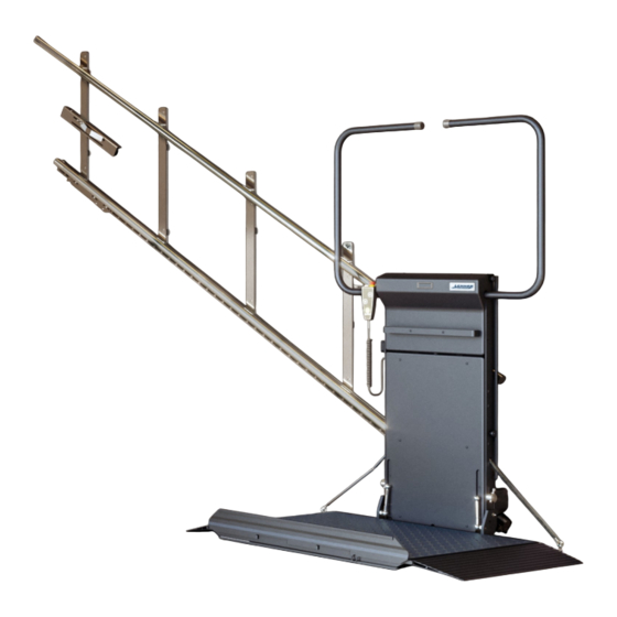
- Page 1 DELTA Installation Manual Edition 04/2024 Installation Manual DELT Platform stairlift DELT platform lift page 1 of 42...
-
Page 2: Table Of Contents
DELTA Installation Manual Edition 04/2024 Table of content OBSERVE THE FOLLOWING POINTS BEFORE INSTALLATION! ........3 INSTALLATION OF THE STEEL RAILS ................4 INSTALLATION OF ALUMINIUM RAILS ................6 ASSEMBLY OF THE RAIL ACCORDING TO INSTALLATION PLAN: ......9 OVERVIEW PLATFORM COMPONENTS ................ 10 INSTALLATION MATERIAL FOR FIXING OF THE RAIL: .......... -
Page 3: Observe The Following Points Before Installation
DELTA Installation Manual Edition 04/2024 Observe the following points before installation! Installation teams must have a general knowledge in: • working on electric controls • basic mechanical engineering and providing adequate fixation of the rails and pillars • reading and understanding circuit diagrams and wiring schematics The following points are necessary for the installation: •... -
Page 4: Installation Of The Steel Rails
DELTA Installation Manual Edition 04/2024 Installation of the STEEL RAILS The rails can be fixed directly to the wall or on pillars that are fixed to the staircase. Upper cam Bracket Pillar Charging station and mechanical limit assembly Step 1: If there are 2 rail sections, combine both rail sections. - Page 5 DELTA Installation Manual Edition 04/2024 Step 3: First fix the upper bracket to the wall or to the upper pillar (pillars have the serial letters stamped on the base). The required dimensions for the first fixing point are given in the drawing –...
-
Page 6: Installation Of Aluminium Rails
DELTA Installation Manual Edition 04/2024 Installation of ALUMINIUM RAILS On the following pages are only to follow in case you receive the aluminium. Separate parts of the rails: Rail assembled: DELT platform lift page 6 of 42... - Page 7 DELTA Installation Manual Edition 04/2024 Details of assembly:: Verbindung von Bügeln und Schienenprofilen: DELT platform lift page 7 of 42...
- Page 8 DELTA Installation Manual Edition 04/2024 Connection between rail parts (in case you need to prolong rail): Untere Schienenverbindung: Obere Schienenverbindung: DELT platform lift page 8 of 42...
-
Page 9: Assembly Of The Rail According To Installation Plan
DELTA Installation Manual Edition 04/2024 Assembly of the rail according to installation plan: See you installation drawing of the exact distances between the brackets that connect the upper and lower rail. The angle of the rail can be adjusted by an angle setting tool or by taking the angel measure W between 2 opposite fixing points as indicated below. -
Page 10: Overview Platform Components
DELTA Installation Manual Edition 04/2024 Overview platform components DELT platform lift page 10 of 42... -
Page 11: Installation Material For Fixing Of The Rail
DELTA Installation Manual Edition 04/2024 Installation material for fixing of the rail: For concrete walls: For concrete walls: For concrete walls: For brick walls: For brick walls: Adhesive 2 components glue for brick wall installation – injection pistol and adhesive ... -
Page 12: Installing The Platform Onto The Rail
DELTA Installation Manual Edition 04/2024 Installing the platform onto the rail There are 2 possibilities/options how to install the platform. But first the following points have to be done: • Turn on main powre switch on platform. • Take off all covers on the backside of the platform. - Page 13 DELTA Installation Manual Edition 04/2024 ATTENTION: TAKE GREAT CARE THAT THE RAIL PASS WELL THROUGH THE NARROW PARTS OF THE LOWER CARRIAGE. IT MUST NOT HIT THE METAL PARTS INSIDE THE LOWER CARRIAGE. Now bring the platform with the rail to the lower stop position. You can move the rail up and down by using the remote control (drive into and out of carriage) and by this way you can match the rail brackets fix screws on the brackets on the upper side.
-
Page 14: Option 2: Drive The Platform Onto The Installed Rail (Platform Needs To Be Taken To Upper Stop And Lifted Onto The Rail!)
DELTA Installation Manual Edition 04/2024 Option 2: Drive the platform onto the installed rail (platform needs to be taken to upper stop and lifted onto the rail!) If you wish to reduce the weight of the complete unit, you can dismantle the platform floor from the carriage. -
Page 15: Very Important: Fixation Of The Upper Carriage
DELTA Installation Manual Edition 04/2024 Very important: Fixation of the upper carriage ! Step 6: Open the upper and lower frontal covers of the carriage. At delivery of the unit the upper carriage will be moveable (can rotate). This will facilitate the process of engaging the platform onto the rails. -
Page 16: Installing Of The Charging Station/Limit Assembly
DELTA Installation Manual Edition 04/2024 Installing of the charging station/limit assembly The position of the charging stations/limit assembly has to be adjusted so the limit switches on the lower carriages are pressed by the mechanical stop at the correct spot. -
Page 17: Adjusting Of The Control Cams
DELTA Installation Manual Edition 04/2024 Adjusting of the control cams Adjust the control cams - the levers for unblocking of the barrier must be in the middle of the control cams when the platform arrives in the stop position. 2 levers for unblocking... -
Page 18: Last Checks Before Using The Stairlift
DELTA Installation Manual Edition 04/2024 Last checks before using the stairlift Before going into operation, check again the correct measurements and fixings and make sure there can be no collision between the platform and the staircase or any other obstacle. Make sure that the travel clearances are correct and all strut fasteners tightened. -
Page 19: Switches And Jumpers On The Control Unit
DELTA Installation Manual Edition 04/2024 Switches and jumpers on the control unit Connector for service display Acoustic buzzer HF1 Button S1 for remote programming Radio remote receiver Switch S2 connector menu type selection Jumpers JP3, JP4 for left/right sided platform installation ... - Page 20 DELTA Installation Manual Edition 04/2024 S2 switch This switch selects between user/service menu types. User mode Service mode/menu WARNING: After the platform installation and setting all service menu parameters, push the switch S2 to the position for user menu!!! Jumpers JP3 and JP4 Jumpers JP3 and JP4 must be set properly according to left sided and right sided installation.
-
Page 21: Led Signalization On Platform's Control Unit
DELTA Installation Manual Edition 04/2024 LED signalization on platform’s control unit LD45 overcurrent rsv. drive LD2 alarm (input) active LD44 overcurrent floor drv LD43 overcur. main drive LD46 low battery LD42 status LED ST8 LD3 input S20 active LD41 status LED ST4... - Page 22 SV1; Goes off when platf. enters slowdown before stop SV2; Goes off when platf. enters slowdown in curve (for straight- LD15 green rail DELTA always lights) LD16 green S29; always on for DELTA rail without middle station LD17 green S33; reserve LD18 green S34; reserve S15;...
- Page 23 (not used for Delta) LD46 Lights when battery voltage is low LD47 Lights when quadrature input 2 is activated (not used for Delta) LD48 Lights when quadrature input 1 is activated (not used for Delta) LD49 Relay KH; Lights when main relay is activated Status LED In the following table there are all status LED combinations described.
-
Page 24: Position Switches On Platform
DELTA Installation Manual Edition 04/2024 Position switches on platform Following schematics show states of position switches (and related LEDs) in dependency on the position of the floor and the barriers. DELT platform lift page 24 of 42... - Page 25 DELTA Installation Manual Edition 04/2024 Platform front view – switch position: S11S1 S11S2 EK-R1 EK-L1 S11M EK-R2 EK-L2 S11U S11P S11O 4xS17 IN CASE WHEN THE PLATFORM IS EQUIPPED WITH ONLY SINGLE RAMP, SWITCH S12 (S13) TYPE FR607 LOCATED ON THE SIDE WITHOUT THE RAMP IS REPLACED BY TWO SWITCHES TYPE FR501 INSTALLED IN THE FLOOR (SAFETY BAR IS INSTALLED INSTEAD OF THE RAMP).
- Page 26 DELTA Installation Manual Edition 04/2024 Platform backside view – switch position: (S27) (S28) SAFETY GEAR S22O S22U (S22U) (S22O) S16-SV1 M1, V2 MOTOR WITH BRAKE INFORMATION IN BRACKETS IS VALID FOR RIGHT RAIL MOTOR AND SAFETY GEAR ARE MIRROR-INSTALLED BY RIGHT RAIL...
-
Page 27: Display Functions
DELTA Installation Manual Edition 04/2024 Display functions The dispaly can be used to analyse errors and for system configuration. Following chapters illustrate and describe functions individually. A special service mode allows a technician to enter into a menu and change system configuration and read error messages. - Page 28 DELTA Installation Manual Edition 04/2024 Menu activation Menu can be entered by pushing both direction buttons (Up AND down) on the platform controller for at least 5 second. Another way is to activate emergency stop-button and simultaneously push any of direction buttons on the platform controller for at least 5 second (this way is suitable for platform controllers with joystick –...
-
Page 29: Menu Items
DELTA Installation Manual Edition 04/2024 Menu items In the following table there are all menu items listed and briefly described for both user and service menu. There is also indication for each item whether it it available in user, service or both menus. - Page 30 DELTA Installation Manual Edition 04/2024 In the following paragraphs some of menu items will be described. Factory default settings are underlined in following lists. These settings can be restored by resetting system to factory default settings. Device info First row shows the type of device Alpha new and the version of HW and SW. Second row shows factory number –...
- Page 31 DELTA Installation Manual Edition 04/2024 Acknowledge error If the menu item is active, all errors that occurred are acknowledged. Errors which must be acknowledged by service men are mentioned in the table of errors. Operation time Menu item Value Name...
- Page 32 DELTA Installation Manual Edition 04/2024 Radio controller version Menu item Value Name Description Radio version TX-OMDE-V-01 Allows radio module version setting. (Schmidiger) Reserve for other (future) type of radio controller Motor configuration Menu item Value Name Description Overcurrent threshold settings Main drive 15…40...
-
Page 33: Error And Operation Diagnostic On The Display
Sets speed for drive down into DOWN station Curve UP 10…80 % PWM Sets speed for drive up in curves (not in use for straight Delta) Curve 10…80 % PWM Sets speed for drive down in curves DOWN (not in use for straight Delta) - Page 34 DELTA Installation Manual Edition 04/2024 Following errors are recorded in EEPROM but they don’t block operation of chair stairlift – don’t need acknowledgement. Error ID Shown display text Description EMERGENCY STOP F201 Emergency STOP-button SI: S7X Input S16 (and also S14...
- Page 35 DELTA Installation Manual Edition 04/2024 Following errors are not recorded in EEPROM and they also don’t block further operation of stairlift – don’t need acknowledgement. They’re shown as long as the error is present and corresponding control buttons are activated.
- Page 36 DELTA Installation Manual Edition 04/2024 Shown display text Description PLATF. UNDEF.POS Controller is not able to evaluate the position of the floor SI: S11x nedef. MAN-UNABLE this is standard message for manual platform which is not able to AUT-S11x nedef.
-
Page 37: Adjustment Of The Platform Inclination
DELTA Installation Manual Edition 04/2024 Adjustment of the platform inclination To adjust the platform horizontally, change the adjustment screws as shown in the picture. Check in loaded condition! Counter the adjusting screw with the counter nut after successful adjustment. Caution: Check if both adjusting screws are... -
Page 38: Adjustment Of The Loading Ramps
DELTA Installation Manual Edition 04/2024 Adjustment of the loading ramps Adjust the ramps to achieve a 45 ° angle between the platform and ramp when the barrier is in horizontal position. When the barrier is open, the ramp has to fit to the bottom of the landing area. -
Page 39: Configuration Of The Remote Radio Controls
DELTA Installation Manual Edition 04/2024 Configuration of the remote radio controls To programme the remotes the button S1 on the control board (next to where the receiver is connected to) has to be pressed until the LED on the receiver start to blink faster. - Page 40 DELTA Installation Manual Edition 04/2024 The remote radio controls have different LED status indications. The below status refers to the radio control model TX-OMDE-V-01: LED status Description Green light Radio signal ok and drive command is active Orange light Radio signal ok and platform is not driving or folding A reason can be that the platform is driven from the platform control or that a safety circuit is open in the electrical system.
-
Page 41: Dismantle The Platform Floor
DELTA Installation Manual Edition 04/2024 Dismantle the platform floor • Dismantle the ball bearing connection between sliding mechanism and platform • Disconnect platform rod connection for sidewall • Dismantle safety under-pan of the platform • Disconnect spring inside platform floor. You might need to manually compress the spring in order to uninstall the connection. -
Page 42: Adjustment Of The Overload Switch
DELTA Installation Manual Edition 04/2024 Adjustment of the overload switch If the unit is equipped with an overload device it is mounted at the lower right part of the sidewall. The platform with full load presses the spring washers and if the real load exceeds the rated load by around 25% then the switch is activates and departure from the landing stop position is blocked by the overload switch.
Need help?
Do you have a question about the DELTA and is the answer not in the manual?
Questions and answers