
Related Manuals for Lehner Lifttechnik ALPHA


Summary of Contents for Lehner Lifttechnik ALPHA
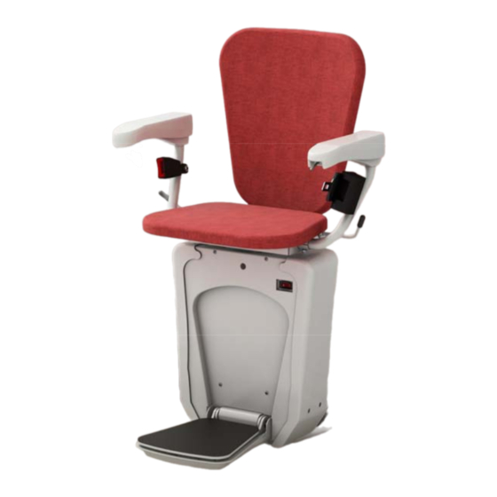
- Page 1 Installation Manual ALPHA C h a i r - s t a i r l i f t Web: www.lehner-lifttechnik.at Tel: +4372783514 Email: office@lehnerlifttechnik.at Mobile: +436645453689...
-
Page 2: Table Of Contents
Stairlift ALPHA Installation Manual Edition March 2014 CONTENTS OBSERVE THE FOLLOWING POINTS BEFORE INSTALLATION! ........2 INSTALLATION OF THE RAILS ..................3 INSTALLATION OF THE DRIVE UNIT ONTO THE RAIL ........... 5 EXPLANATION OF UPPER AND LOWER TROLLEY ............7 ... -
Page 3: Observe The Following Points Before Installation
Stairlift ALPHA Installation Manual Edition March 2014 Observe the following points before installation! Installation teams must have a general knowledge in: working on electric controls basic mechanical engineering and providing adequate fixation of the rails and pillars reading and understanding circuit diagrams and wiring schematics The following points are necessary for the installation: ... -
Page 4: Installation Of The Rails
Stairlift ALPHA Installation Manual Edition March 2014 Installation of the rails Pillar Connection between first and second rail part Pillar height measured from the center of upper rail Step 1: Start fixing the rail from the bottom! Do not start installation from the top. - Page 5 Stairlift ALPHA Installation Manual Edition March 2014 Step 5: Fix the rail parts with the locking pin. Tighten the other pillars at the correct height with the 3 worm screws. Step 6: When all rail parts are connected and all pillars a set to the correct height check again all clearance measures and the correct position of the rail according to the installation drawing.
-
Page 6: Installation Of The Drive Unit Onto The Rail
Stairlift ALPHA Installation Manual Edition March 2014 Installation of the drive unit onto the rail Step 1: Take the box with the drive unit close to the upper end of the rail. Open the box so that the rails and trolleys are on the top of the box. Take out the drive unit and place it on the floor so that it is standing upright Step 2: Take off the wooden plates on each side. - Page 7 Stairlift ALPHA Installation Manual Edition March 2014 Step 3: Take of the side and front plastic covers. Then put the chair into the fixation and fix and lock it with the screw and washer from inside the drive unit. Washer and screw Step 4: Use cable ties to fix the connection cable between from the chair to the drive unit.
-
Page 8: Explanation Of Upper And Lower Trolley
Stairlift ALPHA Installation Manual Edition March 2014 Explanation of upper and lower trolley Contact safety pad switches Curve speed reduction lever Contact safety pad switches Oversspeed governor switch Overspeed governor Pins – see below The lower pin is the ultimate stop pin. This activates the safety switch at the end of the rail (in case the normal stop would not work). -
Page 9: Speed Reduction Lever (Slowdown Arm) For Curve Speed
Stairlift ALPHA Installation Manual Edition March 2014 Speed reduction lever (slowdown arm) for curve speed Take of the top metal cover of the upper trolley and take out a foam cube that is located between the speed control pin and the back of the trolley. This foam is there so the speed reduction lever cannot get bent when the drive unit is put onto the rails at the start of the installation. -
Page 10: Installing Of The Charging Station/Limit Assembly
Stairlift ALPHA Installation Manual Edition March 2014 Installing of the charging station/limit assembly The chairlift is stop when it reaches the end of the charging station by the metal pin pressing the lower carriage contact plate. Make sure the seat stops in the correct place and mark this spot for the charging station. - Page 11 Stairlift ALPHA Installation Manual Edition March 2014 Checks: Check the correct function of all safety contact pads. These are located on the bottom and top trolley, on the side and below the drive unit and under the footrest. These contact pads should top the lift when pressed against the driving direction.
- Page 12 Stairlift ALPHA Installation Manual Edition March 2014 Control switchboard The LED indication on the switchboard can be used for fault finding. Please check the wiring diagram for more detailed information. Here only some simple advice is given. In this example a right hand side stairlift is located in the lower stop position.
-
Page 13: Overspeed Governor
Stairlift ALPHA Installation Manual Edition March 2014 Overspeed governor Explanation: The overspeed governor is set to trip at 0,3m/s so of speed. The tripping point is set via the length of the activation screw. Screws, pins and springs that keep the governor in place are set by the factory and sealed with paint markings. -
Page 14: Troubleshooting
Stairlift ALPHA Installation Manual Edition March 2014 Troubleshooting The seat does not react at all from the call station or the armrest control Check if LED 24 is on. If not the safety circuit is broken (swivel seat switch, overspeed switch and ultimate stop switch) ... -
Page 15: Attachments
Stairlift ALPHA Installation Manual Edition March 2014 The lift stop during driving upwards with load Check if LED 27 is on. If it is on, turn potentiometer R40 the maximum possible counter-clockwise. Try again. The seat does not stop in the intermediate stop station.
Need help?
Do you have a question about the ALPHA and is the answer not in the manual?
Questions and answers