
Related Manuals for LEGRAND inform DSP EVO 6 KVA


Summary of Contents for LEGRAND inform DSP EVO 6 KVA
- Page 1 UNINTERRUPTIBLE POWER SUPPLY DSP EVO 6-10 KVA OPERATION MANUAL ENGLISH 288717270 KULL.KILAV. DSP EVO 6-10kVA (ING) A5 INF511-Y01-U800-2-01...
- Page 2 All rights reserved. The information in this document is subject to change without notice. Publish statement Thank you for purchasing this series UPS. This series UPS is an intelligent, single phase in single phase out, high frequency online UPS designed by our R&D team who is with years of designing experiences on UPS.
-
Page 3: Table Of Contents
Table Of Content 1. SAFETY ......................... 4 1.1 SAFETY ........................4 1.2 SYMBOL DESCRIPTION ..................4 1.3 DESCRIPTION OF COMMONLY USED SYMBOLS ..........5 2. PRODUCT INTRODUCTION ................... 6 2.1 THE APPEARANCE OF THE PRODUCT .............6 2.2 THE PRINCIPLE OF THE PRODUCT ..............7 2.3 PRODUCT CATEGORY ..................7 3. -
Page 4: Safety
1. Safety This chapter mainly introduces the safety signs and security considerations of 6K/10K series high frequency online ups. Before any operation of equipment, you should read the content of this chapter carefully. 1.1 SAFETY There exists dangerous voltage and high temperature inside the UPS. During the installation, operation and maintenance, please abide the local safety instructions and relative laws, otherwise it will result in personnel injury or equipment damage. -
Page 5: Description Of Commonly Used Symbols
There are three levers of safety grade: Dangerous, Warning and Attention. The remark is on the right side of the safety symbol, the detailed comments are shown as following: Dangerous: Indicate risk of serious injury or death or seriously damage of the equipment. Warning: Indicate risk of serious injury or damage of the equipment. -
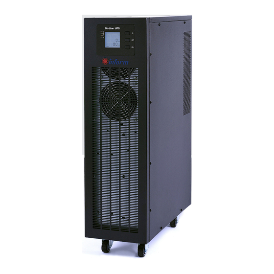
Page 6: Product Introduction
2. Product Introduction 2.1 THE APPEARANCE OF THE PRODUCT 2.1.1 6k/10K-S Fig.1 6/10kVA(S) Fig.2 6/10kVA(S)Rear Fig.3 6/10kVA(S) Front Panel view Panel view (without Rear Panel view (with Maintenance) Maintenance) 1. USB 1. USB 2. RS232 2. RS232 3. EPO 3. EPO 4. -
Page 7: The Principle Of The Product
2.2 THE PRINCIPLE OF THE PRODUCT Maintenance Switch Bypass Input Output Rectifier Inverter Switch Input Switch Charger Battery Group Fig. 2-1 UPS Principle Diagram Input filter: Complete filtering the input AC utility power to provide the clean power for UPS. AC/DC converter: Convert the filtered AC mains to DC and boost the DC for DC/ AC inverter. -
Page 8: Installation
3. Installation 3.1 UNPACKING AND INSPECTION Unpacking the UPS and check that whether it’s damaged during the transporta- tion. If damaged or some parts missing, don’t start the machine and inform the carrier and franchiser. Check the annex (please consult Appendix Table 2). Check if the UPS is just what you wanted to purchase. -
Page 9: Ups Input And Output Connection
Fig.3-2 Wrong power configuration INPUT L OUTPUT L LOAD INPUT N OUTPUT N 3.3 UPS INPUT AND OUTPUT CONNECTION Minimum 10AWG copper wires are required for the 6KVA, and 8AWG for 10KVA, including input/output cables, battery cables. Switch off all breakers before connecting cables Remove the cover of the terminals, see Fig 3-3, following it to connect the cables Fig.3-3 I/O terminals connection Bat+... -
Page 10: Connection Of The Ups Communication Cables
3.4 CONNECTION OF THE UPS COMMUNICATION CABLES RS-232 cable provided in accessories can be used to connect the UPS with PC Follow steps below to install SNMP (if purchased): A. Remove the cover of SNMP slot at UPS rear panel and keep it for further use. B. -
Page 11: Panel Display, Operation And Running
WARNING: Before installing battery, make sure that the UPS and breaker are all turned off. ώ Remove all your metallic adornment such as finger ring, watch, and so on before connecting battery. No anti-connection or short circuit between the battery anode and cathode fore- ώ... -
Page 12: Turn Off Operation
4.1.2 Turn off operation Turn off the UPS in line mode (without batteries) a) Press and hold the OFF key for 2 seconds to turn off the inverter and the UPS is in Bypass mode now; on the contrary, you may press the hold the OFF key for 2 seconds in order to change over back to inverter mode. -
Page 13: Lcd Display
4.2.2 LCD display NOTICE! The display provides more functions than those described in this manual. There are 10 interfaces available in the LCD display: ITEM Interface Description Content Displayed Voltage & Frequency Input Voltage & Current Bat. + Voltage & Current Bat. - Page 14 Battery ( 2 ) Input voltage ( 3 ) Bat + voltage (Positive) Output ( 4 ) Bat – voltage (Negative) ( 5 ) Output voltage 20% load per gird ( 6 ) Load ( 7 ) PFC/ Ambient temperature up, only shows the high tempera- ture Internal...
- Page 15 ( 8 ) Alarm Code ( 9 ) Software version & model ( 10 ) Bus voltage If some of above interfaces have battery charging, it will display the charging information at the same time as shown below. Charging Input Input Boost Floating...
-
Page 16: Parameters Setting
4.3 PARAMETERS SETTING The setting function is controlled by 3 buttons (Enter , Off ▲, On ▼): Enter ---goes into the setting page and value adjustment; Off ▲ & On ▼---for choosing different pages. After the UPS turn ON, press buttons & ▲ for 3 seconds and then goes into the setting interface page. -
Page 17: Output Frequency Class Setting
4.3.3 Output frequency class setting When under the output voltage setting press On▼ or when under battery capacity setting press Off▲, it goes to the frequency setting. The frequency line flashes as in above picture. • Use button Enter to choose the different frequen- cy. -
Page 18: Battery Quantity Setting
4.3.5 Battery quantity setting When under the battery capacity setting press On▼ or when under bypass voltage upper limit setting press Off▲, it goes to the battery quantity setting. The battery quantity line flashes as in above picture. • Use button Enter to choose the different battery quantity. -
Page 19: Bypass Volt-Lo Setting
4.3.7 Bypass Volt-Lo setting When under the bypass voltage upper limit setting press On▼ or when under Buzzers mute setting press Off▲, it goes to the bypass lower limit setting. The bypass lower limit line flashes as in above picture. (“-” for negative, positive does not have any symbol.) •... -
Page 20: Battery Test Setting
4.3.9 Battery Test Setting Battery self-test setting When choosing On1, UPS can transfer to Battery Mode This page is the introduction automatically per 30 days. And to the Battery self-test setting. the Battery Self-test Time is 10 The default Settings is “OFF” seconds. -
Page 21: Display Messages/ Records
4.4 DISPLAY MESSAGES/ RECORDS This section lists the event and alarm messages that the UPS might display. The messages are listed in alphabetical order. This section is listed with each alarm message to help you troubleshoot problems. 4.4.1 Operational Status and Mode(s) Item Content Displayed Fault... -
Page 22: Alarm Information
4.4.2 Alarm Information Item UPS Alarm Warning Buzz Rectifier Fault Beep continuously Fault LED lit Inverter fault (Including Beep continuously Fault LED lit Inverter bridge is shorted) Inverter Thyristor short Beep continuously Fault LED lit Inverter Thyristor broken Beep continuously Fault LED lit Bypass Thyristor short Beep continuously Fault LED lit Bypass Thyristor broken... - Page 23 Item UPS Alarm Warning Buzz Battery over voltage Once per second Fault LED blinking Mains Site Wiring Fault Once per second Fault LED blinking Bypass Site Wiring Fault Once per second Fault LED blinking Output Short-circuit Once per second Fault LED blinking Rectifier over current Once per second Fault LED blinking...
-
Page 24: Maintenance
NOTICE: The following process must be performed if UPS is connected with generator: • First turn on generator, after it runs stably connect output power of generator to UPS input terminal, then turn on UPS. After UPS turned on, please connect load one-by-o- •... -
Page 25: Troubleshooting And Performance Of The Product
6. Troubleshooting and performance of the product In case the UPS can not work normally, it might be wrong in installation, wiring or operation. Please check these aspects first. If you need help, contact our service depart- ment, the following messages should be provided for analysis: •... -
Page 26: Emc Standard/Safety Standard
6.2 EMC STANDARD/SAFETY STANDARD Our products are manufactured according to the following EMC international grade ώ standard and has passed the CE authentication: EMC standard number Safety standard number IEC62040-2 IEC62040-1 IEC61000-4-2 GB4943-2005 IEC61000-4-3 IEC61000-4-4 IEC61000-4-5 6.3 PRODUCT PERFORMANCE Type 6 kVA 10 kVA Capacity... - Page 27 Model 6 kVA 10 kVA Capacity 5.4kW 9 kW Battery number 16/18/20 Pcs. Can be set Battery type VRLA Charge model Boost charge or float charge auto switch Charge time Boost charge up to 20Hr (Max) Charge current (MAX.) Output type Single phase &...
- Page 28 Model 6 kVA 10 kVA Capacity 5.4kW 9 kW Between Normal and battery mode Between inverter and bypass Noise <55dB (1m) Display LED+LCD Safety Meeting IEC62040-1, GB4943 Max input voltage 320Vac, 1 hour (static) Conduction: IEC 62040-2 Radiation: IEC 62040-2 Harmonics: IEC 62040-2 IEC 62040-2 Isolation resistance...
-
Page 29: Appendix 1 Usb Communication Port Definition
Appendix 1 USB communication port definition Definition of Male port: Pin 1 VCC, Pin 2 D- pin 3 D+, Pin 4 GND Application: use UPSilon2000 Power Management software Available functions of the USB • Monitor UPS power status • Monitor UPS alarm info •... - Page 30 PC RS232 portu UPS RS232 portu Pin 2 Pin 2 UPS send,PC receive Pin 3 Pin 3 PC send, UPS receive Pin 5 Pin 5 ground Available function of RS232: • Monitor UPS power status. • Monitor UPS alarm info. •...
- Page 32 www.informups.com...
Need help?
Do you have a question about the inform DSP EVO 6 KVA and is the answer not in the manual?
Questions and answers