Ruijie RG-N18000-XH Series Hardware Installation And Reference Manual
Hide thumbs
Also See for RG-N18000-XH Series:
- Hardware installation and reference manual (103 pages) ,
- Hardware installation and reference manual (177 pages)

Related Manuals for Ruijie RG-N18000-XH Series


Summary of Contents for Ruijie RG-N18000-XH Series
- Page 1 RG-N18000-XH Series Switches Hardware Installation and Reference Guide Document version: V2.0 Date: March 19, 2024 Copyright © 2024 Ruijie Networks...
- Page 2 Unless agreed upon otherwise in the contract, Ruijie Networks does not provide any explicit or implicit statements or warranties regarding the content of this document.
-
Page 3: Preface
Preface Intended Audience This document is intended for: Network engineers Technical support and servicing engineers Network administrators Technical Support Ruijie Networks website: https://www.ruijienetworks.com/ Online support center: https://ruijienetworks.com/support Case portal: https://caseportal.ruijienetworks.com Community: https://community.ruijienetworks.com ... - Page 4 Note The manual offers configuration information (including model, port type and command line interface) for indicative purpose only. In case of any discrepancy or inconsistency between the manual and the actual version, the actual version prevails.
-
Page 5: Table Of Contents
Contents Preface ..............................I 1 Overview ............................1 1.1 About the RG-N18000-XH ......................1 1.2 Component Modules ........................1 1.3 Chassis ............................2 1.3.1 RG-N18010-XH ......................2 1.3.2 RG-N18018-XH ......................9 1.4 Supervisor Modules ......................... 17 1.4.1 M18000XH-CM ......................17 1.4.2 M18000XH-CM II ...................... - Page 6 1.7.1 RG-PAH3000I-F ......................43 1.8 Fan Module ..........................47 1.8.1 M18010XH-FAN ......................47 1.8.2 M18018XH-FAN ......................50 1.8.3 M18010XH-FAN III ....................... 53 1.8.4 M18018XH-FAN III ....................... 56 1.9 Cables ............................58 1.9.1 Console Cable ......................58 1.9.2 Ethernet Cable ......................59 1.9.3 Power Cord ........................
- Page 7 2.2.4 Temperature ......................... 66 2.2.5 Humidity ........................67 2.2.6 Cleanliness ........................67 2.2.7 Power Supply ....................... 68 2.2.8 System Grounding ....................... 70 2.2.9 Preventing Electromagnetic Interference ..............71 2.2.10 Surge Protection ......................71 2.3 Rack-Mounting Guidelines....................... 71 2.4 Tools ............................72 2.5 Unpacking the Switch ......................
- Page 8 3.4.1 Installation Guidelines ....................85 3.4.2 Procedure ........................85 3.5 Installing the Fan Module ......................86 3.6 Installing the Power Module..................... 88 3.7 Installing the Switch Fabric Module ..................89 3.7.1 Installation Guidelines ....................89 3.7.2 Procedure ........................90 3.8 Installing the Supervisor Module ..................... 91 3.8.1 Installation Guidelines ....................
- Page 9 5.1 Monitoring ..........................103 5.1.1 Monitoring the LEDs ....................103 5.1.2 Running the CLI Commands ..................103 5.2 Maintenance .......................... 103 5.2.1 Replacing the Supervisor Module ................104 5.2.2 Replacing the Line Card .................... 105 5.2.3 Replacing the Power Module ..................106 5.2.4 Replacing the Fan Module ..................
- Page 10 6.2.10 Optical Port Linkdown ....................119 7 Appendix ............................119 7.1 Labeling Process ........................119 7.1.1 Hand Writing on Labels ....................119 7.1.2 Pasting Labels ......................119 7.1.3 Label Contents ......................120 7.2 Connectors and Media ......................121 7.2.1 100BASE-TX/10BASE-T Port ..................121 7.2.2 1000BASE-T Port ......................
-
Page 11: Overview
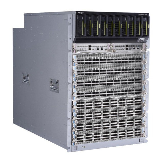
RG-N18000-XH series switch adopts the new Clos architecture, provides 400GE ports, and delivers diverse data center features, which is capable of long-term evolution to 800GE ports. It can be used with Ruijie’s RG-S6930- 2C and RG-S6910-3C switches for a high-performance and high-reliability data center network. -
Page 12: Chassis
Hardware Installation and Reference Guide Overview Supervisor Switch Fabric Chassis Line Card Power Module Fan Module Module Module M18010XH-FAN M18000XH- 36QXS-DB M18000XH- 36CQ-DB M18000XH- 18CQ-DB M18000XH- 48CQ-CES M18018XH- M18000XH-CM RG-PAH3000I-F M18018XH-FAN FE-E IV M18000XH- 36QC-CES M18000XH- RG-N18018- 48XS-DB M18000XH- 36QXS-DB M18000XH-CM M18018XH- M18018XH-FAN... - Page 13 Hardware Installation and Reference Guide Overview 1. Appearance Figure 1-1 Appearance Figure 1-2 Front View...
- Page 14 Hardware Installation and Reference Guide Overview Table 1-3 Front Panel Components Component Chassis header, including logo and model Air intake of power module Mounting bracket Cable management bracket assembly The chassis has two switches for redundancy, as shown in Figure 1-3. The I toggle indicates ON and the O toggle indicates OFF.
- Page 15 Hardware Installation and Reference Guide Overview Figure 1-4 Rear View Table 1-5 Rear Panel Components Component Grounding stud Power receptacle Captive screw of fan module Fan module status Fan module slot Ground for ESD-preventive wrist strap 2. Cooling The working temperature of the RG-N18010-XH ranges from 0° C to 40° C (32° F to 104° F). The cooling system should ensure reliability, security, and maintainability.
- Page 16 Hardware Installation and Reference Guide Overview Figure 1-5 Air Intake Table 1-6 Air Intake of Each Component Component Air intake of power module Air intake of supervisor module Air intake of line card Figure 1-6 Air Exhaust...
- Page 17 Hardware Installation and Reference Guide Overview Table 1-7 Air Exhaust of Each Component Component Air exhaust of power module Air exhaust of supervisor module, switch fabric module, and line card 3. Technical Specifications Table 1-8 Technical Specifications Class Item Specification Without packing materials and cable management brackets: 442 mm x 896 mm x 708 mm (17.40 in.
- Page 18 Hardware Installation and Reference Guide Overview Class Item Specification Noise Sound pressure level at 27° C (80.6° F): < 78 dB AC power protection Surge protection Common mode: 6 kV Differential mode: 6 kV Power supply mode HVDC Power connector Three-pin connector, subject to the power module With the M18010XH-FAN modules: 18,760 W Max power consumption...
-
Page 19: Rg-N18018-Xh
Hardware Installation and Reference Guide Overview Class Item Specification Mean Time to Recovery 0.5 hours (MTTR) Availability 0.9999984 Power redundancy N + M Fan redundancy N + 1 Hot swapping Hot swappable power and fan modules GB/T 9254.1 Regulation Safety GB 4943.1 compliance Environment protection... - Page 20 Hardware Installation and Reference Guide Overview 1. Appearance Figure 1-7 Appearance...
- Page 21 Hardware Installation and Reference Guide Overview Figure 1-8 Front View Table 1-9 Front Panel Components Component Chassis header, including logo and model Air intake of power module Mounting bracket Cable management bracket assembly The chassis has two switches for redundancy, as shown in Figure 1-3. The I toggle indicates ON and the O toggle indicates OFF.
- Page 22 Hardware Installation and Reference Guide Overview Caution Remove supervisor modules, line cards, switch fabric modules, and power modules from the chassis before handling or transporting the chassis. Set the power switch of the chassis to OFF before unplugging the power cord. Figure 1-9 Rear View Table 1-10 Rear Panel Components...
- Page 23 Hardware Installation and Reference Guide Overview 2. Cooling The working temperature of the RG-N18018-XH ranges from 0° C to 40° C (32° F to 104° F). The cooling system should ensure reliability, security, and maintainability. The RG-N18010-XH draws air for heat dissipation. ...
- Page 24 Hardware Installation and Reference Guide Overview Component Air intake of supervisor module Air intake of line card Figure 1-11 Air Exhaust Table 1-12 Air Exhaust of Each Component Component Air exhaust of power module Air exhaust of supervisor module, switch fabric module, and line card...
- Page 25 Hardware Installation and Reference Guide Overview 3. Technical Specifications Table 1-13 Technical Specifications Class Item Specification Without cable management brackets: 442 mm x 1052 mm x 1345 mm (17.10 in. x 41.42 in. x 52.95 in., 31 RU) Dimensions With cable management brackets: 442 mm x 1091 mm x 1345 mm (17.10 in.
- Page 26 Hardware Installation and Reference Guide Overview Class Item Specification AC: 100 V AC to 240 V AC, 50 Hz to 60 Hz Voltage HVDC: 240 V DC to 380 V DC Max power With the M18010XH-FAN modules: 38,900 W consumption With the M18010XH-FAN III modules: 18,000 W Rated voltage range: 100 V to 176 V;...
-
Page 27: Supervisor Modules
Hardware Installation and Reference Guide Overview Class Item Specification compliance Safety GB 4943.1 Environment Environment protection regulation protection Warning Operation of this equipment in a residential environment could cause radio interference. This equipment is not suitable for use in locations where children are likely to be present. ... - Page 28 Hardware Installation and Reference Guide Overview 2. Ports Table 1-14 Ports Connector Port Description Accessory Type The SFP+ port can be auto-negotiated to the data rate of 1 Gbps, mainly used as the VSL interface. Subject to 10GE optical module SFP+ port the optical Working mode: Full-duplex...
- Page 29 Hardware Installation and Reference Guide Overview Connector Port Description Accessory Type The console port is connected to a console for local configuration. Standards compliance: RS-232 Console port RJ45 Console cable Working mode: Duplex Universal Asynchronous Receiver/Transmitter (UART) Baud rate: ○ Range: 9,600 bits/s to 115,200 bits/s ○...
- Page 30 Hardware Installation and Reference Guide Overview Silkscreen Description Label Active/Standby Solid green: The module is the active supervisor module. Primary supervisor Off: The module is the standby supervisor module. module LED Solid yellow: Temperature alarm affects system performance, but the system can continue to work.
- Page 31 Hardware Installation and Reference Guide Overview Silkscreen Description Label Solid green: The switch is using the USB serial port. Mini-USB port status LED Off: The switch is using the RJ45 serial port. 5. Technical Specifications Table 1-17 Technical Specifications Class Item Specification 2.2 GHz octa-core...
-
Page 32: M18000Xh-Cm Ii
Hardware Installation and Reference Guide Overview 1.4.2 M18000XH-CM II 1. Appearance Figure 1-14 Appearance Figure 1-15 Front View 2. Ports Table 1-18 Ports Connector Port Description Accessory Type The SFP+ port can be auto-negotiated to the data rate of 1 Gbps, mainly used as the VSL interface. Subject to 10GE optical module SFP+ port... - Page 33 Hardware Installation and Reference Guide Overview Connector Port Description Accessory Type The USB port is connected with a USB flash drive for configuration backup and firmware upgrade. USB 2.0 FAT32 file format Note USB port USB 2.0 flash drive To ensure data security and prevent damage to your equipment, use USB flash drives of well-known brands and good quality.
- Page 34 Hardware Installation and Reference Guide Overview 3. LEDs Table 1-19 LEDs Silkscreen Description Label Solid green: The system is operating normally. Blinking green: The system is starting up. Solid red: System status ○ The system (including all modules) is not functioning properly. Status ○...
- Page 35 Hardware Installation and Reference Guide Overview Silkscreen Description Label Solid yellow: The port has made a successful 10/100 Mbps link. Blinking yellow: The port is sending and receiving traffic at 10/100 Management Mbps. LINK/ACT port status Solid green: The port has made a successful 1,000 Mbps link. Blinking green: The port is sending and receiving traffic at 1,000 Mbps.
-
Page 36: Line Cards
Hardware Installation and Reference Guide Overview Line Cards 1.5.1 M18000XH-48CQ-CES 1. Appearance Figure 1-16 Appearance Figure 1-17 Front View Note The M18000XH-48CQ-CES has three rows of ports. The top row includes ports 1F, 4F, 7F…46F, the middle row includes ports 2F, 5F, 8F…47F, and the bottom row includes ports 3F, 6F, 9F…48F. ... - Page 37 Hardware Installation and Reference Guide Overview 2. Ports Table 1-21 Ports Connector Port Description Accessory Type The 100GE QSFP28 port is backward compatible with the 40GE QSFP+ module for downlink data transmission. Working mode: Full-duplex 100GE optical module Optical attributes: Subject to the module or Subject to 100GE cable...
-
Page 38: M18000Xh-36Qc-Ces
Hardware Installation and Reference Guide Overview Without packing materials: 437.6 mm x 515 mm x 55.4 mm Dimensions (17.23 in. x 20.28 in. x 2.18 in.) Physical (W x D x H) Without packing materials: 693 mm x 573 mm x 223 mm characteristics (27.28 in. - Page 39 Hardware Installation and Reference Guide Overview 2. Ports Table 1-24 Ports Connector Port Description Accessory Type The 400GE QSFP-DD port is backward compatible 400GE QSFP-DD 400GE Subject to with the 100GE module for uplink data transmission. module QSFP-DD the optical Working mode: Full-duplex 100GE optical module port...
-
Page 40: M18000Xh-48Xs-Db
Hardware Installation and Reference Guide Overview Max. power Power supply 1,610 W consumption Reliability Hot swapping Supported 1.5.3 M18000XH-48XS-DB 1. Appearance Figure 1-20 Appearance Figure 1-21 Front View Note The M18000XH-48XS-DB has two rows of ports. The ports on the top row start with 1 followed by the remaining odd-numbered ports, and the ports on the bottom row start with 2 followed by the remaining even-numbered ports. - Page 41 Hardware Installation and Reference Guide Overview 3. LEDs Table 1-28 LEDs Silkscreen Description Label Solid green: The line card is operating normally. Blinking green: The line card is starting up. Continuous blinking Line card Status indicates an anomaly. status LED Solid red: The line card is not functioning properly.
-
Page 42: M18000Xh-36Qxs-Db
Hardware Installation and Reference Guide Overview 1.5.4 M18000XH-36QXS-DB 1. Appearance Figure 1-22 Appearance Figure 1-23 Front View Note The M18000XH-36QXS-DB has two rows of ports. The ports on the top row start with 1 followed by the remaining odd-numbered ports, and the ports on the bottom row start with 2 followed by the remaining even-numbered ports. - Page 43 Hardware Installation and Reference Guide Overview 3. LEDs Table 1-31 LEDs Silkscreen Description Label Solid green: The line card is operating normally. Blinking green: The line card is starting up. Continuous blinking Line card Status indicates an anomaly. status LED Solid red: The line card is not functioning properly.
-
Page 44: M18000Xh-36Cq-Db
Hardware Installation and Reference Guide Overview 1.5.5 M18000XH-36CQ-DB 1. Appearance Figure 1-24 Appearance Figure 1-25 Front View Note The M18000XH-36CQ-DB has two rows of ports. The ports on the top row start with 1 followed by the remaining odd-numbered ports, and the ports on the bottom row start with 2 followed by the remaining even-numbered ports. - Page 45 Hardware Installation and Reference Guide Overview 3. LEDs Table 1-34 LEDs Silkscreen Description Label Solid green: The line card is operating normally. Blinking green: The line card is starting up. Continuous blinking Line card Status indicates an anomaly. status LED Solid red: The line card is not functioning properly.
-
Page 46: M18000Xh-18Cq-Db
Hardware Installation and Reference Guide Overview Reliability Hot swapping Supported Note The M18000XH-36CQ-DB module supports line-rate forwarding only when used with the N18010XH-FE-D II or the N18018XH-FE-D II module. 1.5.6 M18000XH-18CQ-DB 1. Appearance Figure 1-26 Appearance Figure 1-27 Front View Note The M18000XH-18CQ-DB has two rows of ports. - Page 47 Hardware Installation and Reference Guide Overview 2. Ports Table 1-36 Ports Connector Port Description Accessory Type The 100GE QSFP28 port is backward compatible with the 40GE QSFP+ module and can be split into four 10GE or 25GE ports for downlink data transmission.
-
Page 48: Switch Fabric Module
Hardware Installation and Reference Guide Overview 4. Technical Specifications Table 1-38 Technical Specifications Class Item Specification 2.2 GHz quad-core Technical Memory DDR4 4 GB SDRAM indicators NOR flash: 16 MB (for BootROM) Flash Memory NAND flash: 8 GB Without packing materials: 437.6 mm x 515 mm x 55.4 mm (17.23 Dimensions in. -
Page 49: M18018Xh-Fe-E Iv
Hardware Installation and Reference Guide Overview 2. LEDs Table 1-39 LEDs Silkscreen Description Label Solid green: The switch fabric module is operating normally. Blinking green: The switch fabric module is starting up. Continuous Switch fabric Status blinking indicates an anomaly. module LED Solid red: The switch fabric module is not functioning properly. - Page 50 Hardware Installation and Reference Guide Overview Figure 1-31 Front View 2. LEDs Table 1-41 LEDs Silkscreen Description Label Solid green: The switch fabric module is operating normally. Blinking green: The switch fabric module is starting up. Continuous Switch fabric Status blinking indicates an anomaly.
-
Page 51: M18010Xh-Fe-D Ii
Hardware Installation and Reference Guide Overview 1.6.3 M18010XH-FE-D II 1. Appearance Figure 1-32 Appearance Figure 1-33 Front View 2. LEDs Table 1-43 LEDs Silkscreen Description Label Solid green: The switch fabric module is operating normally. Blinking green: The switch fabric module is starting up. Continuous Switch fabric Status blinking indicates an anomaly. -
Page 52: M18018Xh-Fe-D Ii
Hardware Installation and Reference Guide Overview Max. power Power supply 210 W consumption Reliability Hot swapping Supported 1.6.4 M18018XH-FE-D II 1. Appearance Figure 1-34 Appearance Figure 1-35 Front View 2. LEDs Table 1-45 LEDs Silkscreen Description Label Solid green: The switch fabric module is operating normally. Blinking green: The switch fabric module is starting up. -
Page 53: Power Module
RG-PAH3000I-F 1. Overview The smart power module for the RG-N18000-XH series supports power consumption management and hot swapping. It can obtain the output power, output current, and operating temperature in real time. The RG-PAH3000I-F supports dual power inputs, including three combination modes: AC and AC, HVDC and HVDC, and AC and HVDC. - Page 54 Hardware Installation and Reference Guide Overview 2. Appearance Figure 1-36 Appearance Figure 1-37 Front View...
- Page 55 Hardware Installation and Reference Guide Overview Figure 1-38 Side View 3. LEDs Table 1-48 LEDs Silkscreen Description Label Solid green: The power input is normal. Blinking green at 0.5 Hz: The input voltage exceeds the limit (under- voltage or over-voltage occurs but the internal auxiliary power module Input is operating normally).
- Page 56 Hardware Installation and Reference Guide Overview 4. Technical Specifications Table 1-49 Technical Specifications Item Specification Without packing materials: 485.54 mm x 104.8 mm x 40.8 mm (19.12 in. x 4.13 in. x 1.61 in.) Dimensions (W x D x H) With packing materials: 635 mm 270 mm 115 mm (25.00 in.
-
Page 57: Fan Module
Hardware Installation and Reference Guide Overview Fan Module 1.8.1 M18010XH-FAN 1. Appearance Figure 1-39 Appearance... - Page 58 Hardware Installation and Reference Guide Overview Figure 1-40 Front View 2. LEDs Table 1-50 LEDs Silkscreen Description Label Solid green: The fan module is operating normally. FAN status Blinking green: The fan module is being initialized. Solid red: The fan module is not functioning properly. Off: The fan module is not receiving power.
- Page 59 Hardware Installation and Reference Guide Overview Item Specification Number of fans Rated voltage 54 V DC Typical power consumption 180 W Max. power consumption 900 W Max. fan rotation speed 15,000 RPM Max. airflow volume 700 CFM Max. air pressure 3,825 Pa Hot swapping Supported...
-
Page 60: M18018Xh-Fan
Hardware Installation and Reference Guide Overview 1.8.2 M18018XH-FAN 1. Appearance Figure 1-41 Appearance... - Page 61 Hardware Installation and Reference Guide Overview Figure 1-42 Front View 2. LEDs Table 1-52 LEDs Silkscreen Description Label Solid green: The fan module is operating normally. FAN status Blinking green: The fan module is being initialized. Solid red: The fan module is not functioning properly. Off: The fan module is not receiving power.
- Page 62 Hardware Installation and Reference Guide Overview 3. Technical Specifications Table 1-53 Technical Specifications Item Specification Without packing materials: 140.2 mm x 124.9 mm x 1107.7 mm (5.52 in. x 4.92 in. x 43.61 in.) Dimensions (W x D x H) With packing materials: 1240 mm x 266 mm x 213 mm (48.82 in.
-
Page 63: M18010Xh-Fan Iii
Hardware Installation and Reference Guide Overview 1.8.3 M18010XH-FAN III 1. Appearance Figure 1-43 Appearance... - Page 64 Hardware Installation and Reference Guide Overview Figure 1-44 Front View 2. LEDs Table 1-54 LEDs Silkscreen Description Label Solid green: The fan module is operating normally. FAN status Blinking green: The fan module is being initialized. Solid red: The fan module is not functioning properly. Off: The fan module is not receiving power.
- Page 65 Hardware Installation and Reference Guide Overview 3. Technical Specifications Table 1-55 Technical Specifications Item Specification Without packing materials: 140.2 mm x 121.7 mm x 612.6 mm (5.92 in. x 4.79 in. x 24.12 in.) Dimensions (W x D x H) With packing materials: 759 mm x 279 mm x 233 mm (29.88 in.
-
Page 66: M18018Xh-Fan Iii
Hardware Installation and Reference Guide Overview 1.8.4 M18018XH-FAN III 1. Appearance Figure 1-45 Appearance... - Page 67 Hardware Installation and Reference Guide Overview Figure 1-46 Front Panel 2. LEDs Table 1-56 LEDs Silkscreen Description Label Solid green: The fan module is operating normally. FAN status Blinking green: The fan module is being initialized. Solid red: The fan module is not functioning properly. Off: The fan module is not receiving power.
-
Page 68: Cables
Hardware Installation and Reference Guide Overview Silkscreen Description Label Solid green: The switch fabric module is operating normally. Blinking green: The switch fabric module is starting up. Continuous Switch fabric blinking indicates an anomaly. module LED Solid red: The switch fabric module is not functioning properly. Off: The switch fabric module is not receiving power. -
Page 69: Ethernet Cable
Hardware Installation and Reference Guide Overview Figure 1-47 Console Cable Table 1-58 Console Cable Components Component Description B connector RJ45 connector with shielded crystal head A connector DB9 RS-232 female connector with blue rubber core Screw Captive screw Cable UL2464, 26 AGW sleeve 1.9.2 Ethernet Cable... -
Page 70: Power Cord
Hardware Installation and Reference Guide Overview 1.9.3 Power Cord 1. Applicable Power Cords Table 1-59 Power Cords Chassis AC/HVDC Power Cord CAB-HVDC-3M-IEC-16A-B CAB-HVDC-3M-GB-16A-B RG-N18010-XH CAB-HVDC-5M-IEC-16A-B CAB-HVDC-5M-GB-16A-B CAB-HVDC-3M-IEC-16A-B CAB-HVDC-3M-GB-16A-B RG-N18018-XH CAB-HVDC-5M-IEC-16A-B CAB-HVDC-5M-GB-16A-B Caution The power cords that come with the power modules comply with standards of the destination country or region, for example, the power cords illustrated in this manual are China-specific power cords. -
Page 71: Grounding Wire
Hardware Installation and Reference Guide Overview Figure 1-49 IEC Standard-Compliant Power Cord 1.9.4 Grounding Wire Table 1-60 Grounding Wire Specifications Rated Cross- Cable Current- Chassis Color Installation Sectional Length Sleeve Carrying Area Capability UL10455 6 Yellow- RG-N18010-XH Crimping 95 A 13.4784 mm 3,000+ 30 mm green... -
Page 72: Pluggable Modules
Caution Always use Ruijie certified pluggable modules. Uncertified pluggable modules may lead to service instability. Ruijie will not claim responsibility for the service problems caused by uncertified pluggable modules or provide a solution. The models of pluggable modules applicable to the chassis are subject to update without notification. -
Page 73: Preparing For Installation
Hardware Installation and Reference Guide Preparing for Installation Preparing for Installation Safety Guidelines Note To avoid personal injury or equipment damage, review the safety guidelines in this chapter before you begin the installation. Only trained and qualified personnel should be allowed to install, replace, or service this equipment. ... -
Page 74: Electricity Safety
Hardware Installation and Reference Guide Preparing for Installation 2.1.3 Electricity Safety Always observe the local regulations and standards. Only trained and qualified personnel should be allowed to operate the equipment. Carefully check your work area for possible hazards, such as ungrounded power extension cables, missing safety grounds, and moist floors. -
Page 75: Laser Safety
Hardware Installation and Reference Guide Preparing for Installation An ESD-preventive socket is located in the lower right corner of the front panel and in the lower left corner of the rear panel respectively. Figure 2-1 Wearing an ESD-Preventive Wrist Strap for the M18010XH Figure 2-2 Wearing an ESD-Preventive Wrist Strap for the M18018XH 2.1.5... -
Page 76: Storage Guidelines
Hardware Installation and Reference Guide Preparing for Installation When an optical transceiver is working, ensure that the port is connected to an optical cable or covered by a dust cap to keep out dust and prevent burning your eyes. ... -
Page 77: Humidity
Hardware Installation and Reference Guide Preparing for Installation Note The operating temperature is measured at the point that is 1.5 m (4.92 ft.) above the floor and 0.4 m (1.31 ft.) before the equipment with no protective plates in front or at the back of the equipment. 2.2.5 Humidity To ensure normal operation and prolonged service life of the equipment, maintain an appropriate humidity in the... -
Page 78: Power Supply
Hardware Installation and Reference Guide Preparing for Installation Table 2-2 Gas Requirement Average Maximum (mg/m mg/m mg/m Sulfur dioxide (SO 0.11 0.37 Hydrogen sulfide (H 0.071 0.36 Chlorine (Cl) 0.034 Nitric oxide (NO) 0.26 0.52 Note The average value is measured over one week. The maximum value is the upper limit of the harmful gas measured in one week for up to 30 minutes every day. - Page 79 Hardware Installation and Reference Guide Preparing for Installation Module Max. Power Consumption (W) M18018XH-FE-E IV 950 W M18018XH-FAN 1,800 W M18010XH-FAN III 610 W M18018XH-FAN III 1,220 W M18000XH-48XS-DB 235 W M18000XH-36QXS-DB 650 W M18000XH-36CQ-DB 650 W M18000XH-18CQ-DB 340 W M18018XH-FE-D II 420 W M18010XH-FE-D II...
-
Page 80: System Grounding
Hardware Installation and Reference Guide Preparing for Installation 2.2.8 System Grounding A reliable grounding system is the basis for stable and reliable operation, which is indispensable for preventing lightning strikes and interference. Carefully check the grounding conditions at the installation site according to the grounding specifications, and complete grounding properly based on the site situation. -
Page 81: Preventing Electromagnetic Interference
Hardware Installation and Reference Guide Preparing for Installation 2.2.9 Preventing Electromagnetic Interference Electromagnetic interference mainly comes from outside the equipment or application system and affects the equipment through capacitive coupling, inductive coupling, electromagnetic waves, and other conduction modes. Interference prevention measures should be taken for the power supply system. ... -
Page 82: Tools
Hardware Installation and Reference Guide Preparing for Installation (3) The square hole rack post is at least 180 mm (7.09 in.) from the front door, and the front door is at most 25 mm (0.98 in.) thick. This ensures an available clearance of at least 155 mm (6.10 in.). The rack depth (distance between front and rear doors) is at least 1,200 mm (47.24 in.). -
Page 83: Unpacking The Switch
Hardware Installation and Reference Guide Preparing for Installation Unpacking the Switch Note Check your goods carefully against Package Contents or purchase contract. If you have any questions, contact your distributor. 2.5.1 Unpacking the Chassis Table 2-4 Unpacking the Chassis Step Description RG-N18018-XH RG-N18010-XH... -
Page 84: Unpacking The Switch Fabric Module
Hardware Installation and Reference Guide Preparing for Installation Two persons are required to slide the shipping box off the pallet base. Remove the static- shielding container. Remove the two L- brackets on each side using an adjustable wrench and a screwdriver. -
Page 85: Unpacking The Line Card
Hardware Installation and Reference Guide Preparing for Installation box is intact. Use a paper cutter to cut the tapes holding the cardboard sleeves of the box, and open the shipping box. Take out the foam block and the inner box from the shipping box. - Page 86 Hardware Installation and Reference Guide Preparing for Installation flat surface, and check whether the seal on top of box is intact. Use a paper cutter to cut the tapes holding the cardboard sleeves of the box, and open the shipping box. Take out the foam block and the inner box from the shipping box.
-
Page 87: Unpacking The Supervisor Module
Hardware Installation and Reference Guide Preparing for Installation 2.5.4 Unpacking the Supervisor Module Table 2-7 Unpacking the Supervisor Module Step No. Description M18000XH-CM Cut off the packing straps on the shipping box with scissors, place the box on a flat surface, and check whether the seal on top of box is intact. -
Page 88: Installing The Switch
Hardware Installation and Reference Guide Installing the Switch Remove the tape on the static- shielding container, open and reach into the bag with both hands, grab the two sides of the chassis, lift the switch out of the static-shielding container, and place it on an ESD-preventive workbench. -
Page 89: Installation Procedure
Hardware Installation and Reference Guide Installing the Switch Installation Procedure Figure 3-1 Installation Procedure Start Prepare Install the chassis. Connect the grounding wire. Install the power module. Connect the power cord. Verify installation. Set the power Troubleshoot switch to ON. Set the power Normal? switch to OFF. - Page 90 Hardware Installation and Reference Guide Installing the Switch Installing the Switch Fabric Module Installing the Supervisor Module Installing the Line Card (10) Installing the Pluggable Module (11) Verifying Installation (12)
-
Page 91: Installing The Rack
Hardware Installation and Reference Guide Installing the Switch (13) Cord Installing the Rack 3.2.1 Installation Guidelines Make sure the following guidelines are met: All expansion bolts for securing the rack base to the ground are installed from bottom to up in the sequence of large flat washer, spring washer, and nut, and the installation holes on the base are flush with the expansion bolts. -
Page 92: Installing The Chassis
Hardware Installation and Reference Guide Installing the Switch Figure 3-2 Shelf Bracket Rail Location Warning Make sure that the shelf bracket rails can bear weight of the chassis and its component modules. Install the chassis in the rack as required. ... -
Page 93: Procedure
Hardware Installation and Reference Guide Installing the Switch 3.3.2 Procedure (1) Based on the shelf bracket rail location, measure the height of L-brackets and determine the locations of cage nuts with the aid of the included mounting template. Mark the locations and install cage nuts on the marked square holes on the front rack posts. - Page 94 Hardware Installation and Reference Guide Installing the Switch Figure 3-5 Mounting the RG-N18010-XH in a Standard 19-Inch or Scorpio Rack Figure 3-6 Mounting the RG-N18018-XH in a Standard 19-Inch or Scorpio Rack Note The chassis provides three bracket location options for adapting to the racks with different depths. Install the brackets according to actual conditions.
-
Page 95: Installing The Protective Grounding Wire
Hardware Installation and Reference Guide Installing the Switch Figure 3-7 Bracket Location Options Installing the Protective Grounding Wire 3.4.1 Installation Guidelines A reliable grounding system is the basis for stable and reliable operation, which is indispensable for preventing lightning strikes and interference. The chassis has a grounding stud on its rear panel. Connect the grounding stud to the grounding terminal of the rack and then connect the grounding terminal to the grounding bar of the equipment room. -
Page 96: Installing The Fan Module
Hardware Installation and Reference Guide Installing the Switch ● The maintenance personnel should check whether the AC power socket is reliably connected to the building's protective ground. If not, the maintenance personnel should use a protective grounding wire to connect the protective ground terminal of the AC power socket to the building's protective ground. ●... - Page 97 Hardware Installation and Reference Guide Installing the Switch Figure 3-8 Installing the Fan Module 2. Installing the M18018XH-FAN or the M18018XH-FAN III Wear an ESD-preventive wrist strap and an ESD-preventive glove, ensuring that the ESD-preventive wrist strap makes good skin contact and is electrically connected to ground. (1) Press the buttons beside the handholds to eject the handholds.
-
Page 98: Installing The Power Module
Hardware Installation and Reference Guide Installing the Switch Figure 3-9 Installing the Fan Module Installing the Power Module Wear an ESD-preventive wrist strap that is electrically connected to ground, ensuring that it makes good skin contact. The RG-N18000-XH provides ten power module slots. To improve system stability and availability, you are advised to power on dual power domains for each power module. -
Page 99: Installing The Switch Fabric Module
E series switch fabric module as an example. 3.7.1 Installation Guidelines The RG-N18000-XH series chassis adopts the Clos architecture and midplane-free design, and the switch fabric module and the line card are orthogonally interconnected. The switch fabric module is inside the fan tray. To remove the switch fabric module, take out the fan tray in advance. -
Page 100: Procedure
Hardware Installation and Reference Guide Installing the Switch 3.7.2 Procedure (1) Position the switch fabric module in front of the open slot, unlatch the ejector levers, and insert the switch fabric module into the slot. (2) Slide the switch fabric module into the slot until you feel it snap into place. (3) Close the ejector levers. -
Page 101: Installing The Supervisor Module
M18000XH-CM as an example. 3.8.1 Installation Guidelines The RG-N18000-XH series chassis provides two supervisor module slots on the front panel. Before you begin (1) Wear an ESD-preventive wrist strap and an ESD-preventive glove, ensuring that the ESD-preventive wrist strap is electrically connected to ground. -
Page 102: Installing The Line Card
3.9.1 Installation Guidelines The RG-N18000-XH series chassis provides eight line card slots on the front panel. Before you begin (1) Wear an ESD-preventive wrist strap that is electrically connected to ground. (2) Remove the replacement card from its packing materials. -
Page 103: Installing M18000Xh-48Cq-Ces And M18000Xh-36Qc-Ces
Hardware Installation and Reference Guide Installing the Switch Figure 3-14 Installing the Line Card Caution If a slot is to remain empty, install a filler panel to allow for adequate airflow and to keep dust out of the chassis. ... - Page 104 Hardware Installation and Reference Guide Installing the Switch Figure 3-15 Pulling out a Pair of Ejector Levers Attach the ejector levers to the ejector lever retainers of the line card. Figure 3-16 Attaching Ejector Levers to Ejector Lever Retainers (3) Hold the line card with one hand, and place your other hand underneath the line card to support it. Position the line card in front of the open slot.
- Page 105 Hardware Installation and Reference Guide Installing the Switch Figure 3-17 Sliding the Line Card into the Slot (4) Keep pressing the ejector levers for 3 seconds after they lock in place. Make sure that the ejector levers engage behind the front of the slot so that the line card plugs into the receptacle at the back of the slot. Figure 3-18 Pivoting Ejector Levers Inward and Pressing Them for Three Seconds Screw in the captive screws to seat the line card firmly in the slot.
- Page 106 Hardware Installation and Reference Guide Installing the Switch Figure 3-19 Seating the Line Card Firmly in the Slot (6) Press the spring tab on each ejector lever retainer to remove the ejector levers. Place the ejector levers back inside the chassis and keep them secure for future use.
- Page 107 Hardware Installation and Reference Guide Installing the Switch Figure 3-20 Placing Ejector Levers back Inside the Chassis Caution If a slot is to remain empty, install a filler panel to allow for adequate airflow and to keep dust out of the chassis.
-
Page 108: Installing The Pluggable Module
Hardware Installation and Reference Guide Installing the Switch 3.10 Installing the Pluggable Module Note Make sure that you have mounted the chassis in the rack before installing the pluggable module. For procedure, see Optical Module Hardware Installation and Reference Guide for details. 3.11 Connecting the Power Cord Connect the power cord according to the notation on the power module and location requirements. - Page 109 Hardware Installation and Reference Guide Installing the Switch The power cord is long enough to avoid over-extension. The power socket is connected to the earth ground as required with a rated current of at least 10 A. Each power module receives power from a power socket.
-
Page 110: Commissioning
Hardware Installation and Reference Guide Commissioning Commissioning Setting Up the Configuration Environment Connect the serial port of a PC to the console port of the device with a cable, as shown in Figure 4-1. Figure 4-1 Configuration Environment The first login to the device must be performed through the console port. (1) Connect the serial port of a PC to the console port of the device with a standard RS-232 cable. - Page 111 Hardware Installation and Reference Guide Commissioning Click Serial in the left column. Set Bits per second to 115,200, Data bits to 8, Parity to None, Stop bits to 1, and Flow control to None. Click Open to set up the connection.
-
Page 112: Powering On The Device
Hardware Installation and Reference Guide Commissioning (4) After setting up the configuration environment, power on the device. If the device is already configured with a password, a notification will appear. Click Accept, and enter your username and password for connection. Powering on the Device 4.2.1 Checklist Before Power-on... -
Page 113: Monitoring And Maintenance
Hardware Installation and Reference Guide Monitoring and Maintenance Monitoring and Maintenance Monitoring 5.1.1 Monitoring the LEDs Each module installed in the chassis features a LED, which can be used to monitor the status of each module while the switch is running. See 1 Overview for details. -
Page 114: Replacing The Supervisor Module
Hardware Installation and Reference Guide Monitoring and Maintenance 5.2.1 Replacing the Supervisor Module 1. Before you begin (1) Wear an ESD-preventive wrist strap and an ESD-preventive glove, ensuring that the ESD-preventive wrist strap is electrically connected to ground. (2) Remove the replacement module from its packing materials. 2. -
Page 115: Replacing The Line Card
Hardware Installation and Reference Guide Monitoring and Maintenance Figure 5-2 Installing the Supervisor Module Caution If a slot is to remain empty, install a filler panel to allow for adequate airflow and to keep dust out of the chassis. ... -
Page 116: Replacing The Power Module
Hardware Installation and Reference Guide Monitoring and Maintenance Figure 5-3 Removing the Line Card Figure 5-4 Installing the Line Card Caution If a slot is to remain empty, install a filler panel to allow for adequate airflow and to keep dust out of the chassis. -
Page 117: Replacing The Fan Module
Hardware Installation and Reference Guide Monitoring and Maintenance Caution After hot swapping a power module, wait for at least 30 seconds before proceeding with next hot swapping operation. Make sure that the chassis is secured to avoid the chassis falling down during power module swapping. ... - Page 118 Hardware Installation and Reference Guide Monitoring and Maintenance 1. Before you begin (1) Wear an ESD-preventive wrist strap and an ESD-preventive glove, ensuring that the ESD-preventive wrist strap is electrically connected to ground. (2) Remove the replacement module from its packing materials. 2.
- Page 119 Hardware Installation and Reference Guide Monitoring and Maintenance Figure 5-8 Installing the M18010XH-FAN Replacing the M18018XH-FAN (1) Use a Phillips screwdriver to loosen the captive screws. (2) Press the buttons beside the handholds to eject the handholds. Avoid any obstacles along the ejection path.
- Page 120 Hardware Installation and Reference Guide Monitoring and Maintenance Figure 5-9 Removing the M18018XH-FAN...
-
Page 121: Replacing The Switch Fabric Module
Hardware Installation and Reference Guide Monitoring and Maintenance Figure 5-10 Installing the M18018XH-FAN 5.2.5 Replacing the Switch Fabric Module The switch fabric module is inside the fan tray. To remove the switch fabric module, take out the fan tray in advance. - Page 122 Hardware Installation and Reference Guide Monitoring and Maintenance 2. Procedure To ensure no packet drop upon replacement, run the power off command to power off the switch fabric module before replacing it. The replacement module will be powered on automatically. For example, before replacing FE3, run the power off slot fe3 command in privileged EXEC mode and confirm the operation.
- Page 123 Hardware Installation and Reference Guide Monitoring and Maintenance Figure 5-12 Switch Fabric Module Layout for the RG-N18018-XH (1) Run the power off command and check whether the switch fabric module is powered off. (2) Remove the fan tray where the switch fabric module resides. Unlatch the ejector levers on the switch fabric module.
-
Page 124: Replacing The Cable Management Bracket
Hardware Installation and Reference Guide Monitoring and Maintenance Figure 5-14 Replacing the Switch Fabric Module for the RG-N18018-XH Figure 5-15 Caution Do not hold the removed switch fabric module using ejector levers. Do not lift the switch fabric module until it is fully disengaged from the chassis. Pay attention to connector protection. -
Page 125: Replacing The Lithium Battery
Hardware Installation and Reference Guide Monitoring and Maintenance Figure 5-16 Replacing the Cable Management Bracket 5.2.7 Replacing the Lithium Battery The equipment has a built-in lithium battery to maintain the real-time clock without external power supply. To replace the lithium battery, please contact your distributor or technical support team. Danger ●... -
Page 126: Troubleshooting
Hardware Installation and Reference Guide Troubleshooting Troubleshooting Flowchart The equipment is not working properly. Check whether the rack is installed properly. Check whether the chassis is mounted on the rack properly. Check whether the power cord is connected properly. Check whether the power module is installed properly. -
Page 127: Common Issues
Hardware Installation and Reference Guide Troubleshooting Common Issues 6.2.1 Forgetting Login Password Symptom The login password is forgotten. Handling Method Contact technical support team. 6.2.2 AC Power Module Failure Symptom All LEDs on the front panel are off. The fan status LED is off, and the fan does not rotate. Handling Method Unplug the power cord from the power module. -
Page 128: Supervisor Module Led Exception
Hardware Installation and Reference Guide Troubleshooting 6.2.5 Supervisor Module LED Exception Handling Method The Status LED of the supervisor module becomes abnormal after the supervisor module is powered on or works for some time. For example, the status LED is blinking or off, and the alarm LED is red. Handling Method Check whether the supervisor module is firmly seated in the slot. -
Page 129: Optical Port Linkdown
Hardware Installation and Reference Guide Appendix (1) Check whether the line card is installed in place. (2) If the fault persists, contact Shen Zhen SDG DONZHI Technology for technical support. 6.2.10 Optical Port Linkdown Symptom The system runs normally. After you insert an optical transceiver into an optical port and plug in an optical cable, the link cannot be set up. -
Page 130: Label Contents
Hardware Installation and Reference Guide Appendix Figure 7-1 Keeping the Label Text Area Facing Right or Downwards (2) Labeling procedure Figure 7-2 Signal Cable Labeling Procedure 7.1.3 Label Contents The contents of both sides of the label identify the location of the ports connected to the two ends of the power cord. -
Page 131: Connectors And Media
Hardware Installation and Reference Guide Appendix Figure 7-3 Signal Cable Label Connectors and Media 7.2.1 100BASE-TX/10BASE-T Port Table 7-1 100BASE-TX/10BASE-T Pin Assignment MDI Mode MDI-X Mode Output Transmit Data+ Input Receive Data+ Output Transmit Data– Input Receive Data-– Input Receive Data+ Output Transmit Data+ Input Receive Data–... - Page 132 Hardware Installation and Reference Guide Appendix for data transmission. Figure 7-6 shows the twisted pair connection for the 1000BASE-T port. The connection method and signal description are provided considering self-made cables. Keep the side without the RJ45 locking clip facing yourself. The signal cables are numbered 1 to 8 from left to right. Figure 7-6 Cable Connection Modes and Signals Table 7-2...
-
Page 133: Surge Protection
Hardware Installation and Reference Guide Appendix Figure 7-7 1000BASE-T Twisted Pair Connections Surge Protection 7.3.1 Installing an AC Power Arrester When an AC power cord from outdoors is directly plugged into the power port of the switch, the AC power connector must be connected to an external surge protector power strip to protect the switch against lightning strikes. -
Page 134: Installing An Ethernet Port Arrester
Hardware Installation and Reference Guide Appendix Figure 7-8 Power Arrester Note The power arrester does not come with the equipment. Please purchase it based on actual requirements. Important points: Make sure that the PE terminal of the power arrester is well grounded. ... - Page 135 Hardware Installation and Reference Guide Appendix (1) Tear one side of the protective paper for the double-sided adhesive tape and paste the tape to the enclosure of the Ethernet port arrester. Tear the other side of the protective paper for the double-sided adhesive tape and paste the Ethernet port arrester to the switch enclosure.
-
Page 136: Site Selection
Hardware Installation and Reference Guide Appendix Site Selection The equipment room should be at least 5 km (16,404.20 ft.) away from heavy pollution sources, such as the smelter works, coal mine, and thermal power plant. The equipment room should be at least 3.7 km (12,139.11 ft.) away from medium pollution sources, such as the chemical factory, rubber factory, and electroplating... - Page 137 Hardware Installation and Reference Guide Appendix cords are routed beside the rack, and top cabling or bottom cabling is adopted according to the locations of the DC power distribution box, AC power socket, or surge protection box in the equipment room. ...
- Page 138 Hardware Installation and Reference Guide Appendix corners. The metal hole traversed by cables should have a smooth and fully rounding surface or an insulated lining. Use cable ties to bundle up cables properly. Please do not connect two or more cable ties to bundle up cables. ...
- Page 139 Hardware Installation and Reference Guide Appendix For the cable terminals fastened by screw threads, tighten the bolt or screw and take cable retention measures, as shown in Figure 7-13. Figure 7-13 Cable Fastening Hard power cords should be fastened in the terminal connection area to prevent stress on terminal connection and cable.
Need help?
Do you have a question about the RG-N18000-XH Series and is the answer not in the manual?
Questions and answers