Ruijie RG-N18000-X Series RG-N18010-X Hardware Installation And Reference Manual
Hide thumbs
Also See for RG-N18000-X Series RG-N18010-X:
- Hardware installation and reference manual (122 pages)
Table of Contents
Advertisement
Quick Links
Advertisement
Table of Contents

Related Manuals for Ruijie RG-N18000-X Series RG-N18010-X


Summary of Contents for Ruijie RG-N18000-X Series RG-N18010-X
- Page 1 RG-N18000-X Series Switches Hardware Installation and Reference Guide V1.22...
- Page 2 This document is provided “as is”. The contents of this document are subject to change without any notice. Please obtain the latest information through the Ruijie Networks website. Ruijie Networks endeavors to ensure content accuracy and will not shoulder any responsibility for losses and damages caused due to content omissions, inaccuracies or errors.
- Page 3 Appendix B "Mini-GBIC Modules" Appendix C “Lightening Protection” Appendix D “Cabling Recommendations in Installation” Appendix E “Site Selection” Obtaining Technical Assistance Ruijie Networks Website: https://www.ruijienetworks.com/ Technical Support Website: https://ruijienetworks.com/support Case Portal: https://caseportal.ruijienetworks.com Community: https://community.ruijienetworks.com...
- Page 4 Means reader be careful. In this situation, you might do something that could result in equipment damage or loss of data.
-
Page 5: Product Overview
Hardware Installation and Reference Guide Product Overview 1 Product Overview Launched by Ruijie independently, RG-N18000-X series next generation core switches adopt the Clos architecture and support large buffer. RG-N18000-X series support dual supervisor modules and redundancy of power supply, switch fabric and fan modules. - Page 6 Hardware Installation and Reference Guide Product Overview Operating 0° C to 40° C (32° F to 104° F) Temperature Storage -40° C to 70° C (-40° F to 158° F) Temperature Operating Humidity 10% to 90% RH (non-condensing) Storage Humidity 5% to 95% RH Long term operation height: 3000m at 35°...
- Page 7 Hardware Installation and Reference Guide Product Overview Front Panel The front panel of the RG-N18018-X switch is shown in the following figure. Figure 1-2 Front Panel of the RG-N18018-X Switch...
- Page 8 Hardware Installation and Reference Guide Product Overview ① Model name ⑤ Supervisor module slot Note ② Cable management brackets ⑥ Service module slot ③ Air intake of the power supply module ⑦ Anti-static wrist strap ④ Bracket Ensure the supervisor module, service module, switch fabric module and power supply module are removed from the chassis before you move or transport the RG-N18018-X chassis.
- Page 9 Hardware Installation and Reference Guide Product Overview ① Power supply module ④ Fan module LED Note ② Fan module slot ⑤ Captive screws of the fan module ③ Anti-static wrist strap jack ⑥ Grounding point Power supply The RG-N18018-X switch adopts both AC and DC power supply input. ...
- Page 10 Hardware Installation and Reference Guide Product Overview ① Air intakes for supervisor modules Note: ② Air intakes for service modules ③ Air intakes for power modules Figure 1-5 Ventilation and Heat Dissipation System of the RG-N18018-X Switch (Exhaust Vents)
- Page 11 Hardware Installation and Reference Guide Product Overview ① Exhaust vents for power modules Note: ② Exhaust vents for switch fabric, service and supervisor modules For the supervisor and service modules, air flows across the chassis from the front intakes to the back vents. For the power supply modules, air flows in from the front intakes and out from the back vents.
- Page 12 Hardware Installation and Reference Guide Product Overview The chassis should be mounted in a place with sufficient space for air circulation. Sufficient space (10 cm at least) must be reserved at the air intakes and exhaust vents for ventilation. If any module slot is unoccupied, install a filler panel to ensure proper airflow. Ensure there is at least one filler panel installed in two neighboring unoccupied slots.
- Page 13 Hardware Installation and Reference Guide Product Overview Operation altitude: -500m to 5,000m MTBF 418,000 hours 62 dB at 27° C (80.6° F) Noise 87 dB at 50° C (122° F) Weight 52kg (114.64lbs) Cable management brackets excluded: 442 mm x 961 mm x 534 mm(17.40 in. x 37.83 in. x Dimensions 21.02 in.), 12U (W x D x H)
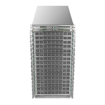
- Page 14 Hardware Installation and Reference Guide Product Overview Front Panel The front panel of the RG-N18010-X switch is shown in the following figure Figure 1-7. Figure 1-7 Front Panel of the RG-N18010-X Switch...
- Page 15 Hardware Installation and Reference Guide Product Overview ① Model name ⑤ Supervisor module slot Note ② Cable management brackets ⑥ Service module slot ③ Air intake of the power supply module ⑦ Anti-static wrist strap ④ Bracket Ensure the supervisor module, service module, switch fabric module and power supply module are removed from the chassis before you move or transport the RG-N18010-X chassis.
- Page 16 Hardware Installation and Reference Guide Product Overview ① Power supply module ④ Fan module LED Note ② Fan module slot ⑤ Captive screws of the fan module ③ Anti-static wrist strap jack ⑥ Grounding point Power Supply AC input: The RG-PA2700I power supply module is supported. This type of power supply module supports power management.
- Page 17 Hardware Installation and Reference Guide Product Overview ① Air intakes for supervisor modules Note: ② Air intakes for service modules ③ Air intakes for power supply modules Figure 1-10 Ventilation and Heat Dissipation System of the RG-N18010-X Switch (Exhaust Vents)
- Page 18 Hardware Installation and Reference Guide Product Overview ① Exhaust vents for power supply modules Note: ② Exhaust vents for switch fabric, service and supervisor modules For supervisor and service modules, air flows in from the front intakes and out from the back vents. ...
- Page 19 Hardware Installation and Reference Guide Product Overview Specifications Model RG-N18006-X Module Slot Two supervisor module slots, four service module slots and six switch fabric module slots Supervisor Module M18006X-CM II Supervisor Module Supported Redundancy Switch Fabric Module M18006X-FE-C I M18000X-36CQ-CB M18000X-36QXS-CB M18000X-18CQ-CB M18000X-48XS2CQ-CB...
- Page 20 Hardware Installation and Reference Guide Product Overview RG-N18006-X switch is a class A product. In a domestic environment, this product may cause radio interference in which case the user may be required to take adequate measures. Product Appearance The hardware system of the RG-N18006-X switch is composed of the chassis, power system, system modules and cooling system.
- Page 21 Hardware Installation and Reference Guide Product Overview ① Model name ⑤ Supervisor module slot Note ② Cable management brackets ⑥ Service module slot ③ Power supply module ⑦ Anti-static wrist strap ④ Bracket Ensure the supervisor module, service module, switch fabric module and power supply module are removed from the chassis before you move or transport the RG-N18006-X chassis.
- Page 22 Hardware Installation and Reference Guide Product Overview ① Fan module slot ④ Captive screws of the fan module Note ② Anti-static wrist strap jack ⑤ Grounding point ③ Fan module LED Power Supply AC input: The RG-PA3000I power supply module is supported. This type of power supply module supports power management.
- Page 23 Hardware Installation and Reference Guide Product Overview ① Air intakes for supervisor modules Note: ② Air intakes for service modules ③ Air intakes for power supply modules Figure 1-15 Ventilation and Heat Dissipation System of the RG-N18006-X Switch (Exhaust Vents)
- Page 24 Hardware Installation and Reference Guide Product Overview Note: ① Exhaust vents for power supply, switch fabric, service and supervisor modules For supervisor and service modules, air flows in from the front intakes and out from the back vents. For the power supply modules, air flows in from the front intakes and out from the back vents.
- Page 25 Hardware Installation and Reference Guide Product Overview External Port The M18000X-CM II module provides four external ports: Universal Serial Bus (USB) port: By connecting to the USB port, the USB storage devices can store logs, host version, alarms and other diagnosis information, facilitating online upgrade of switch software and storage of logs. To secure data and prevent damage to the device, it is recommended to use high-quality flash disks produced by reliable manufacturers.
- Page 26 Hardware Installation and Reference Guide Product Overview Initialization is in progress. Continuous blinking indicates Blinking green errors. (Any module is being initialized.) Solid green The fan is operational. The fan is NOT in the position. (The fan tray is NOT in the Fan status LED position or is NOT receiving power.) Solid red...
- Page 27 Hardware Installation and Reference Guide Product Overview External Port The M18000X-CM II-C module provides four external ports: Universal Serial Bus (USB) port: By connecting to the USB port, the USB storage devices can store logs, host version, alarms and other diagnosis information, facilitating online upgrade of switch software and storage of logs. To secure data and prevent damage to the device, it is recommended to use high-quality flash disks produced by reliable manufacturers.
- Page 28 Hardware Installation and Reference Guide Product Overview stacks In stacking mode, the module is the primary supervisor Solid green module. The module is NOT receiving power or is NOT in the position. Solid green The module is operational. Switch fabric module status Solid red One of the modules is faulty.
- Page 29 Hardware Installation and Reference Guide Product Overview EMC Standards GB9254-2008 CLASS A Safety Standards GB4943-2011 Operating 0° C to 45° C (32° F to 113° F) Temperature Storage -40° C to 70° C (-40° F to 158° F) Temperature Operating Humidity 10% to 90% RH (non-condensing) MTBF 265,000 hours...
- Page 30 Hardware Installation and Reference Guide Product Overview Press the button, and the system starts to collect information, during which the device will not restart. After the collection is complete, the device restarts automatically. Hold the button for a while, the system starts to collect information.
- Page 31 Hardware Installation and Reference Guide Product Overview Blinking The MGMT port is transmitting or receiving data. Mini USB port LED RJ45 serial port is in use. Solid green USB serial port is in use. Specifications Model M18006X-CM II 16-core CPU, each core with the clock speed of 1.5G BOOTROM 8 MB Flash Memory...
- Page 32 Hardware Installation and Reference Guide Product Overview External Port It provides 36 QSFP28 ports. The QSFP28 ports support 100G QSFP28 modules, 40G QSFP+ modules, as well as 100G-4x25G and 40G-4x10G optical interface modules. Hot swapping of the M18000X-36CQ-CB and QSFP28/QSFP+ modules is supported.
- Page 33 Hardware Installation and Reference Guide Product Overview Temperature Operating Humidity 10%-90% RH (non-condensing) MTBF 100,000 hours Weight Net weight: 10.25 kg Dimensions 429 mm x 522 mm x 50 mm (W x D x H) 1.4.5 M18000X-18CQ-CB Module Appearance Figure 1-20 Appearance of the M18000X-18CQ-CB Module External Port It provides 18 QSFP28 ports.
- Page 34 Hardware Installation and Reference Guide Product Overview 100GBASE-SR4 MMF 100GBASE-LR4 SMF 100GBASE-iLR4 SMF 100GBASE-eSR4 MMF Status, Link/ACT Hot Swapping Supported Power Consumption 475W EMC Standards GB9254-2008 CLASS A Safety Standards GB4943-2011 Operating 0° C to 45° C (32° F to 113° F) Temperature Storage -40 to 70°...
- Page 35 Hardware Installation and Reference Guide Product Overview SDRAM DDRIII 4GB Port Type 36 QSFP+ ports, supporting 40G QSFP+ modules and 40G-4x10G optical interface module 40GBASE-SR4 MMF Transmission 40GBASE-LR4 SMF Medium 40GBASE-LSR4 MMF 40GBASE-ER4 SMF Status, Link/ACT Hot Swapping Supported Power Consumption 482W EMC Standards GB9254-2008 CLASS A...
- Page 36 Hardware Installation and Reference Guide Product Overview Blinking The port is transmitting and receiving data. Specifications Model M18000X-48XS2CQ-CB Quad-core CPU, each core with the clock speed of 1.0G BOOTROM 8 MB Flash Memory 1 GB SDRAM DDRIII 4GB Provides 48 SFP+ ports that support 10G SFP+ modules and Gigabit SFP modules, and two Port Type QSFP28 ports that support 100G QSFP28 modules, 40G QSFP+ modules.
- Page 37 Hardware Installation and Reference Guide Product Overview It provides 18 QSFP+ ports and 18 QSFP28 ports. The QSFP+ ports support 40G QSFP+ and 40G-4x10G optical interface modules. The QSFP28 ports support 100G QSFP28 and 40G QSFP+ modules as well as 40G-4x10G optical interface modules.
- Page 38 Hardware Installation and Reference Guide Product Overview (W x D x H) 1.4.9 M18000X-48XT2CQ-CB Figure 1-24 Appearance of the M18000X-48XT2CQ-CB Module Appearance External Port It provides 48 10G RJ45 ports and two QSFP28 ports. The RJ45 ports support 1G/10G auto-negotiation and full duplex. The QSFP28 ports support 100G QSFP28 modules and 40G QSFP+ modules.
- Page 39 Hardware Installation and Reference Guide Product Overview Hot Swapping Supported Power Consumption 304W EMC Standards GB9254-2008 CLASS A Safety Standards GB4943-2011 Operating 0° C to 45° C (32° F to 113° F) Temperature Storage Temperature -40° C to 70° C (-40° F to 158° F) Operating Humidity 10% to 90% RH (non-condensing) MTBF...
- Page 40 Hardware Installation and Reference Guide Product Overview Medium 40GBASE-LR4 SMF 40GBASE-LSR4 MMF 40GBASE-ER4 SMF 100GBASE-SR4 MMF 100GBASE-LR4 SMF 100GBASE-iLR4 SMF 100GBASE-eSR4 MMF Status, Link/ACT Hot Swapping Supported Power Consumption 795W EMC Standards GB9254-2008 CLASS A Safety Standards GB4943-2011 Operating 0° C to 40° C (32° F to 104° F) Temperature Storage -40 to 70°...
- Page 41 Hardware Installation and Reference Guide Product Overview EMC Standards GB9254-2008 CLASS A Safety Standards GB4943-2011 Operating 0° C to 45° C (32° F to 113° F) Temperature Storage -40° C to 70° C (-40° F to 158° F) Temperature Operating Humidity 10% to 90% RH (non-condensing) MTBF 275,000 hours...
- Page 42 Hardware Installation and Reference Guide Product Overview 1.4.13 M18010X-FE-C I Module Appearance Figure 1-28 Appearance of the M18010X-FE-C I Module External Port Identification Status Meaning on the panel The module is NOT receiving power. Solid red The module is faulty. System LED Status Initialization is in progress.
- Page 43 Hardware Installation and Reference Guide Product Overview External Port Identification Status Meaning on the panel The module is NOT receiving power. Solid red The module is faulty. System LED Status Initialization is in progress. Continuous blinking indicates Blinking green errors.
- Page 44 Hardware Installation and Reference Guide Product Overview Initialization is in progress. Continuous blinking indicates Blinking green errors. Solid green The module is operational. Specifications Model M18010X-FE-D I Quad-core CPU , each core with the clock speed of 1.0G BOOTROM 8 MB Flash Memory 16GB (EMMC) SDRAM...
- Page 45 Hardware Installation and Reference Guide Product Overview Power Consumption 589W Hot Swapping Supported EMC Standards GB9254-2008 CLASS A Safety Standards GB4943-2011 Operating 0° C to 40° C (32° F to 104° F) Temperature Storage -40° C to 70° C (-40° F to 158° F) Temperature Operating Humidity 10% to 90% RH (non-condensing)
- Page 46 Hardware Installation and Reference Guide Product Overview Dimensions 47.5 mm x 245.8 mm x 261.4 (W x D x H) 1.4.18 RG-PA2700I Module Appearance Figure 1-33 Appearance of the RG-PA2700I Module External port The RG-PA2700I module provides 54 VAC input to the overall system of the RG-NN18010-X and RG-N18018-X switch.
- Page 47 Hardware Installation and Reference Guide Product Overview Max Voltage 90 VAC to 290VAC; 47/63Hz Range 100VAC to 105VAC power: 1,200W Max Power 105VAC to 176VAC power: 1,450W Output 175VAC to 200VAC power: 2,400W 200VAC to 240VAC power: 2,700W High Current DC 192VDC to 350VDC power: 2,700W Parameter...
- Page 48 Hardware Installation and Reference Guide Product Overview Specifications Module Model RG-PD2400I Rated Voltage -40 VDC to -72VDC Range Max Voltage -40 VDC to -72VDC Range Max Power 2,400W Output Weight Net weight: 2.05 kg (Single module; power cord excluded) Power Cord 60A power cord Requirement When you plug in the power cord, please fasten the anti-loose screw to the power cord to prevent loosening.
- Page 49 Hardware Installation and Reference Guide Product Overview Solid green Solid red Overvoltage. Solid green Solid red Overcurrent. Solid green Solid orange Temperature alarm Solid green Solid red Over-temperature fault Specifications Module Model RG-PA3000I-F Rated Voltage 100-240V~; 50/60Hz Range Max Voltage 90-290V~;...
- Page 50 Hardware Installation and Reference Guide Product Overview ① Captive screws of the fan tray Note: ② Fan status LED ③ Fan handle ④ Nylon slide Composition The M18018X-FAN is the fan for service, management and switch fabric modules on the RG-N18018-X. There are three M18018X-FAN trays drawing air out to form convection for heat dissipation.
- Page 51 Hardware Installation and Reference Guide Product Overview The fan is NOT receiving power or fails. Status Solid green The fan is operational. Solid red The fan is faulty. The corresponding switch fabric module is NOT receiving power. Solid red The corresponding switch fabric module is faulty. FE (two—one on the left The corresponding switch fabric module is being initialized.
- Page 52 Hardware Installation and Reference Guide Product Overview ① Captive screws of the fan tray Note: ② Fan status LED ③ Fan handle ④ Nylon slide Composition The M18010X-FAN is the fan for service, management and switch fabric modules on the RG-N18010-X. There are three M18010X-FAN trays drawing air out to form convection for heat dissipation.
- Page 53 Hardware Installation and Reference Guide Product Overview Composition The M18006X-FAN is the fan for service, management and switch fabric modules on the RG-N18006-X. There are three M18006X-FAN trays drawing air out to form convection for heat dissipation. Specifications Power Weight 2.7 KG Dimension 96.02 mm x...
- Page 54 Hardware Installation and Reference Guide Product Overview Function Meaning Status Monitoring Rotational speed monitoring, failure alarm Automatic Speed-adjustment controlled by temperature Speed-adjustment Hot Swapping Hot swapping is supported by the fan tray.
-
Page 55: Preparation Before Installation
Hardware Installation and Reference Guide Preparation before Installation 2 Preparation before Installation 2.1 Safety Suggestions To avoid body injury and equipment damage, please carefully read the safety suggestions before you install RG-N18000-X. The following safety suggestions do not cover all possible dangers. 2.1.1 General Suggestions ... - Page 56 Hardware Installation and Reference Guide Preparation before Installation Take dust prevention measures in the room. Maintain an appropriate humidity. Always wear an anti-static wrist strap when you touch any circuit board. Try to hold a circuit board by its edges. Do not touch any components or the PCB. ...
-
Page 57: Laser Safety
Hardware Installation and Reference Guide Preparation before Installation Figure 2-2 Preventing EMI on RG-N18010-X 2.1.5 Laser Safety... -
Page 58: Installation Site Requirements
Hardware Installation and Reference Guide Preparation before Installation Among the modules supported by RG-N18000-X, there are a great number of optical modules that are Class I laser products. Precautions: When a fiber transceiver works, ensure that the port has been connected with a fiber or is covered with a dust cap so as to keep out dust and avoid burning your eyes. -
Page 59: Cleanness Requirements
Hardware Installation and Reference Guide Preparation before Installation The ambient humidity is measured at the point that is 1.5m above the floor and 0.4m before the equipment when there is no protective plate in front or back of the equipment rack. 2.2.6 Cleanness Requirements Dust poses the top threat to the running of the equipment. -
Page 60: System Grounding Requirements
Hardware Installation and Reference Guide Preparation before Installation M18000X-6QXS6CQ-CB M18000X-48XT2CQ-CB M18000X-32CQ-DB M18000X-48CQ-CE M18018X-FE-C II M18018X-FE-C V M18010X-FE-C I M18010X-FE-C II M18006X-FE-C I M18018X-FE-D II M18010X-FE-D I M18010X-FE-E II The RG-N18018-X provides N+M redundancy of power supply. You are recommended to use multiple power supplies for the equipment to ensure its continuous and stable operation by avoiding the impact of unexpected power failures on the equipment. -
Page 61: Emi Consideration
Hardware Installation and Reference Guide Preparation before Installation The ground required for EMC design includes shielding ground, filter ground, noise and interference suppression, and level reference. All the above constitute the comprehensive grounding requirements. The grounding resistance should be less than 1Ω. Two grounding points are reserved at the right back of the chassis. The grounding point is pasted with a conspicuous warning label. -
Page 62: Installation Tools
Hardware Installation and Reference Guide Preparation before Installation Be sure that the slide rail in the cabinet is enough to bear the weight of a RG-N18000-X and its installation accessories. Be sure that the cabinet provides an earthing terminal for the switch to be grounded. ... - Page 63 Hardware Installation and Reference Guide Preparation before Installation Device panels are installed and operational. Chassis Carton Fans, screwdriver, wrench, anti-static wrist strap, yellow/green grounding wires, quick installation guide, slide rail, packing list Module Carton Modules, packing list, documentation A normal delivery should contain the above mentioned items, which may differ from the actual delivery, depending on purchase contracts.
-
Page 64: Product Installation
Hardware Installation and Reference Guide Product Installation 3 Product Installation RG-N18000-X series Ethernet switch must be used and fixed in the room. Make sure you have carefully read part 2 and this part, and be sure that the requirements set forth in part 2 have been met. -
Page 65: Mounting The Cabinet
Hardware Installation and Reference Guide Product Installation 3.3 Mounting the Cabinet Precautions When you install the cabinet, pay attention to the following: All expansion bolts for fastening the cabinet base to the ground should be installed and tightened in sequence from bottom up (large plain washer, spring washer, and nut), and the installation holes on the base and the expansion bolts should be well aligned. -
Page 66: Mounting The Switch To A Cabinet
Hardware Installation and Reference Guide Product Installation Before installing a slide rail, make sure that the weight capacity of the slide rail meets requirements. There are variable kinds of slide rails. The rail appearance and installation is subject to actual conditions. In order to keep the cabinet balanced, please install the slide rail to as low a position as possible in the cabinet if only one RG-N18000-X switch is installed. - Page 67 Hardware Installation and Reference Guide Product Installation Figure 3-2 Slide Rail Installation Positions Place the switch on the slide rail, and drive it smoothly into the cabinet until the front bracket reaches the square hole strip. Align the installation holes on the bracket with the cage nuts on the square hole strip, and mount them with screws. Figure 3-3 Mounting the RG-18018X Switch into a 19-Inch IEC Cabinet...
- Page 68 Hardware Installation and Reference Guide Product Installation Figure 3-4 Mounting the RG-18010X Switch into a 19-Inch IEC Cabinet...
-
Page 69: Connecting The System Ground
Hardware Installation and Reference Guide Product Installation 3.5 Connecting the System Ground A good grounding system protects your switch against lightning strikes and interferences and ensures its normal operation and reliability. Precaution The sectional area of the grounding wire should be determined according to the possible maximum current. Cables of good conductor should be used. -
Page 70: Installing Power Supply
Hardware Installation and Reference Guide Product Installation 3.6 Installing Power Supply The RG-N18000-X series switches provide RG-PA2700I RG-PA3000I-F for AC power supplies and RG-PD2400I for DC power supplies. Before performing the following procedures, wear an anti-static wrist strap close to your kin and keep it grounded well. -
Page 71: Installing Fan
Hardware Installation and Reference Guide Product Installation The host power is the summation of the power of all working modules, including the supervisor module, service module and fan. For the power consumption of each module, see the module specifications. 3.7 Installing Fan RG-N18018-X adopts M18018X-FAN module for heat dissipation, RG-18010X adopts M18010-FAN module and RG-18006X adopts M18006-FAN module. - Page 72 Hardware Installation and Reference Guide Product Installation 3.8 Installing Switch Fabric Module An N18000-X series switch adopts the CLOS architecture midplane-free design, and the switch fabric module and service module are orthogonally interconnected. The switch fabric module resides in the fan tray. Therefore, remove the fan tray before installing the switch fabric module.
- Page 73 Hardware Installation and Reference Guide Product Installation Preparation Wear an anti-static wrist strap close to your skin and have it properly grounded. Take out the supervisor module from the package. Steps Pull out the levers on both sides of the supervisor module. Support the bottom of the supervisor module with one hand and hold the supervisor module with the other hand to insert the supervisor module into the slot along the rail.
- Page 74 Hardware Installation and Reference Guide Product Installation 3.10.1 Installing M18000X-48CQ-CE Module M18000X-48CQ-CE cannot be used with switch fabric modules except E-class modules, e.g., M18010X-FE-E II. M18000X-48CQ-CE only supports the chassis of version 2.0. Preparation Wear an anti-static wrist strap close to your skin and have it properly grounded. Take out the service module from the package.
-
Page 75: Installing Swappable Interface Modules (Optional)
Hardware Installation and Reference Guide Product Installation Remove the cable management brackets and install them back onto the chassis. Figure 3-13 Removing Cable Management Brackets In order to ensure the reliability of the system ventilation and heat dissipation performance and address the requirement of the dust-filter, filler panel needs to be installed in the slot where no service module or service module has been installed. -
Page 76: Installing Sfp+/Sfp Modules
Hardware Installation and Reference Guide Product Installation Preparation Wear an anti-static wrist strap to your wrist and tighten the lock. Make sure it is properly grounded. Take out the SFP+/SFP/QSFP+/QSFP28 module you want to install from packing bag. Do not touch the connecting finger on the module. -
Page 77: Installing 40-Gigabit Qsfp+ Modules
Hardware Installation and Reference Guide Product Installation After you connect the copper module to the Ethernet network through the connector, the Link/ACT status is on. Otherwise, please check the connector. Precaution If the SFP+ module cannot be inserted to the end, do not push it forcefully. Please try the other end of the module. ... - Page 78 Hardware Installation and Reference Guide Product Installation Figure 3-19 Installing the QSFP+ Module Equipped with a Pull Tap Use the fiber optical patch cord to connect the 40G QSFP+ module to the fiber optical network. Select the patch cord with the connector corresponding to the port. After the patch cord is connected, the Link/ACT Status LED is on.
-
Page 79: Connecting The Power Cord
Hardware Installation and Reference Guide Product Installation Figure 3-21 Installing the QSFP28 Module Equipped with a Pull Tap Use the fiber optical patch cord to connect the 100G QSFP28 module to the fiber optical network. Select the patch cord with the connector corresponding to the port. After the patch cord is connected, the Link/ACT Status LED is on. - Page 80 Hardware Installation and Reference Guide Product Installation Make sure the socket is powered off before the power cord is connected. Connect the DC power cord Insert the DC power plug into the power module socket. Fasten the anti-loose screw of the power cord onto the power panel. Connect the other end of the power cord to an external power socket.
-
Page 81: System Debugging
Hardware Installation and Reference Guide System Debugging 4 System Debugging 4.1 Establishing the Configuration Environment Establishing the Configuration Environment If you log in to the switch for the first time, please use the Console port. Connecting the Console Cable Connect one end of the DB-9 jack of the console cable to the serial port of the PC. Connect one end of the console cable RJ45 to the Console port of the switch. - Page 82 Hardware Installation and Reference Guide System Debugging Choose Start > Programs > Accessories > Communications > Hyperterminal. The hyperterminal window appears. Click Cancel. A window appears as shown in Figure 4-2. Figure 4-2 In the Connectivity Note window, type the name of the new connection and click OK. A window appears as shown in Figure 4-3.
-
Page 83: Power-On Startup
Hardware Installation and Reference Guide System Debugging After setting the serial port parameters, click OK. The Hyperterminal window appears.. 4.2 Power-on Startup Checking Before Power-on The switch is fully grounded. The power cable is correctly connected. The power supply voltage complies with the requirement of the switch. ... -
Page 84: Monitoring And Maintenance
Replacing Fuses To replace the old fuse wire with the correspondent new one, please contact the technical support representatives of Ruijie Networks. The following table lists the specifications for the module fuses. Module Fuse Slot Number... - Page 85 Hardware Installation and Reference Guide Monitoring and Maintenance M18000X-CM II-C 5A/125V M18000X-CM X 5A/125V M18000X-36CQ-CB F1, F2, F3, F4 30A/125V M18000X-32CQ-DB F1, F2, F3, 30A/125V M18000X-18CQ-CB 30A/125V M18000X-36QXS-CB 30A/125V M18018X-FE-C II 15A/85V M18018X-FE-C V F1, F2 30A/125V M18018X-FE-D II 15A/85V M18010X-FE-C I 15A/85V M18010X-FE-C II...
-
Page 86: General Installation Troubleshooting Flow
Check the connection of the serial port and its parameters Check the connection of the fibers or cables of various ports Contact Technical Support of Ruijie Networks for hardware problems 6.2 Common Troubleshooting Procedures Fault 1: The AC power module does not work. - Page 87 RG-N18000-X Software Configuration Guide. If not, modify the serial port configuration parameters. If there is still no serial port printed information, please contact Ruijie Customer Service Department for technical support. Fault 7: The serial port console outputs illegible characters.
- Page 88 Check whether the rates of the two sides match and whether the optical fiber type meets requirements. In addition, for ports supporting different rates, check whether rate modes are configured correctly. If above mentioned methods do not take effect, please contact Ruijie Networks for technology assistance.
-
Page 89: Replacing Modules
Hardware Installation and Reference Guide Replacing Modules 7 Replacing Modules 7.1 Replacing Swappable Interface Modules (Optional) 7.1.1 Replacing SFP+/SFP Modules Take the following steps to remove SFP/SFP+ modules: Unplug the optical fiber. Turn down the handle of the module until it is horizontal. Pull the tab to take out the SFP/SFP+ module, as shown in Figure 7-1. - Page 90 Hardware Installation and Reference Guide Replacing Modules If you want to remove the module equipped with a bail-clasp latch, turn down the handle of the module until it is horizontal and pull the bail-clasp latch to take out the QSFP+ module, as shown in Figure 7-3. If you want to remove the module equipped with a pull tab, pull the tab to take out the QSFP+ module gently, as shown in Figure 7-3: Figure 7-3 Replacing the QSFP+ Module Equipped a Bail-clasp Latch Figure 7-4 Replacing the QSFP+ Module Equipped with a Pull-tab Latch...
- Page 91 Hardware Installation and Reference Guide Replacing Modules Precaution Unplug the optical fiber before replacing the module. Do not pull out the module forcefully without turning down the handle of the module. Immediately install the dust plug to the module port and the switch fiber port. 7.2 Replacing Supervisor Module Preparation Wear an anti-static wrist strap close to your skin and have it properly grounded.
-
Page 92: Replacing Power Module
Hardware Installation and Reference Guide Replacing Modules Pull out the levers on both sides of the service module. Support the bottom of the service module with one hand and hold the service module with the other hand to insert the service module into the slot along the rail. Drive the levers close to the service module, and the service module will hit the back panel. -
Page 93: Replacing Fan
Hardware Installation and Reference Guide Replacing Modules Note: A: Power modules to be removed B: Power module to be installed 7.5 Replacing Fan Do not touch any bare wire, terminal or the power instruction on the switch. The fan tray supports hot swapping, If you want to remove the fan tray when the switch is operational, do not remove the fan tray until the fan stops rotating, Besides, do not put your hands inside the fan tray. - Page 94 Hardware Installation and Reference Guide Replacing Modules 7.6 Replacing Switch Fabric Module The switch fabric module resides in the fan tray. Therefore, remove the fan tray before replacing the switch fabric module. The N18000-X series switch employs the 2+1 fan tray redundancy solution. Therefore, replace the switch fabric modules in the fan trays one by one, to ensure that the other two fan trays are working.
-
Page 95: Replacing Cable Management Bracket
Hardware Installation and Reference Guide Replacing Modules After the switch fabric module is removed, do not hold the switch fabric module by the ejector lever, to prevent damage caused by sudden fall-off of the switch fabric module. Raise the switch fabric module only after it is totally removed from the cabinet. Protect the front-end high-speed connector and place the removed switch fabric module in an anti-static shielding bag. -
Page 96: Connecting The External Port Cables
Hardware Installation and Reference Guide Cables 8 Cables This chapter describes the precautions and simple steps for cable connection and bundling. See Appendix D cabling Recommendations in Installation for detailed cabling and bundling. 8.1 Connecting the External Port Cables Precautions ... -
Page 97: Appendix A Connectors And Media
Hardware Installation and Reference Guide Appendix A Connectors and Media Appendix A Connectors and Media 1000BASE-T/100BASE-TX/10BASE-T The 1000BASE-T/100BASE-TX/10BASE-T is a 10/100/1000 Mbps auto-negotiation port that supports auto MDI/MDIX. Compliant with IEEE 802.3ab, 1000BASE-T requires Category 5e 100-ohm UTP or STP (STP is recommended) with a maximum distance of 100 meters (328 feet). - Page 98 Hardware Installation and Reference Guide Appendix A Connectors and Media...
-
Page 99: Appendix B Mini-Gbic, 10G And 40G Module
Hardware Installation and Reference Guide Appendix B Mini-GBIC, 10G and 40G Module Appendix B Mini-GBIC, 10G and 40G Module We provide 1000M SFP modules (Mini-GBIC modules), 10G SFP+ modules, 40G QSFP+ modules and 100G QSFP28 modules. According to the interface type of the switch module. You can select modules to suit your specific needs. The following models and technical specifications of some 1000M SFP modules, 10G SFP+ modules and 40G QSFP+ modules are listed for your reference. - Page 100 Hardware Installation and Reference Guide Appendix B Mini-GBIC, 10G and 40G Module interface) The existing 10 G SFP+ copper modules: Copper Module Connector Conductor Wire Support Model Cable Data Rate(Gb/s) Type Type Diameter (AWG) Length(m) (Yes/No) XG-SFP-AOC1M Active SFP+ 10.3125 XG-SFP-AOC3M Active SFP+...
-
Page 101: Appendix C Switch Lightning Protection
Hardware Installation and Reference Guide Appendix C Switch Lightning Protection Appendix C Switch Lightning Protection Installing AC Power Arrester (lightning protection cable row) The external lightning protection cable row shall be used on the AC power port to prevent the switch from being struck by lightning when the AC power cable is introduced from the outdoor and directly connected to the power port of the switch. - Page 102 Hardware Installation and Reference Guide Appendix C Switch Lightning Protection Ethernet port arrester to the switch framework. The paste location for the Ethernet port arrester shall be as close to the grounding terminal of the switch. Based on the distance of the switch grounding terminal, cut the grounding line for the Ethernet port arrester and firmly tighten the grounding line to the grounding terminal of the switch.
-
Page 103: Appendix D Cabling Recommendations In Installation
Hardware Installation and Reference Guide Appendix D Cabling Recommendations in Installation Appendix D Cabling Recommendations in Installation When RG-N18000-X series switches are installed in standard 19-inch cabinets, route cable bundles upward or downward along the sides of the rack depending on the actual situation in the equipment room. All cable connectors should be placed at the bottom of the cabinet rather than be exposed outside of the cabinet. - Page 104 Hardware Installation and Reference Guide Appendix D Cabling Recommendations in Installation If cables are to be bent, bind them first but do not tie cable ties within the bend to avoid stress on the cables, which may otherwise cause the wires inside to break, as shown in Figure D-3. Figure D-3 Do Not Tie Cable Ties within the Bend ...
- Page 105 Hardware Installation and Reference Guide Appendix D Cabling Recommendations in Installation Flat washer Note Spring washer Flat washer When using a stiff cable, fix it near the cable lug to avoid stress on the lug and cable. Do not use self-tapping screws to fasten terminals. ...
-
Page 106: Appendix E Site Selection
Hardware Installation and Reference Guide Appendix E Site Selection Appendix E Site Selection The machine room should be at least 5km away from the heavy pollution source such as the smelter, coal mine and thermal power plant, 3.7km away from the medium pollution source such as the chemical industry, rubber industry and electroplating industry, and 2km away from the light pollution source such as the food manufacturer and leather plant.
Need help?
Do you have a question about the RG-N18000-X Series RG-N18010-X and is the answer not in the manual?
Questions and answers