Table of Contents
Advertisement
Quick Links
Advertisement
Table of Contents

Related Manuals for Wyrestorm MX-0804-SCL


Summary of Contents for Wyrestorm MX-0804-SCL
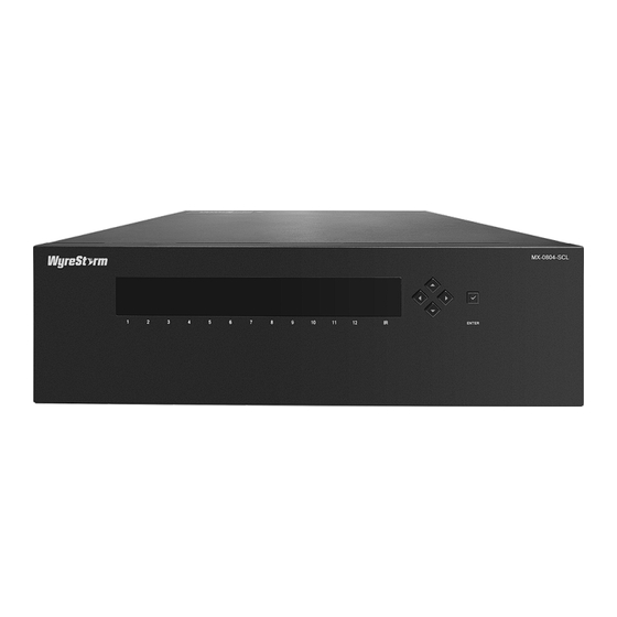
- Page 1 MX-0804-SCL 12 Slot Seamless Modular Matrix User Manual Version: V1.0.0...
- Page 2 Important Safety Instructions 1. Do not expose this apparatus 6. Clean this apparatus to rain, moisture, dripping or only with dry cloth. splashing and that no objects filled with liquids, such as vases, shall be placed on the apparatus. 7. Unplug this apparatus 2.
-
Page 3: Table Of Contents
Table of Contents Introduction ...................... 2 Overview ....................2 Features ....................2 Package Contents ..................3 Specifications ................... 3 Panel Description ..................5 Front Panel ..................5 Rear Panel ..................6 Installation and Wiring ..................7 Installation ....................7 Wiring ....................... 7 Control of the Matrix .................. -
Page 4: Introduction
Introduction Overview This product is a 12-slot modular switching matrix which is configured to have 8x HDMI input and 4x output boards. All inputs and outputs support resolutions up to 4K@60Hz 4:4:4 8bit and compliant with HDCP 2.2. It comes with advanced EDID management to offset conflicts between screens and ensure output of highest resolution compatible to all connected displays. -
Page 5: Package Contents
Package Contents 1 x Matrix 1 x AC Power Cord with only EU Pin 1 x IR Remote 1 x IR Receiver (38KHz) 1 x USB to UART Cable 12 x Phoenix Male Connectors (3.5mm, 5 Pins) ... - Page 6 Technical Analog Audio In: PCM 2.0 VESA: 1024 x 768 , 1280 x 800 , 1600 x 1200 , 1920 x 1200 and AUTO (preferred native timing of the display). Output Resolution Supported SMPTE: 1280 x 720 , 1920 x 1080 , 3840 x 2160 , 3840 x 2160 1 = at 23.98 Hz, 2 = at 24 Hz, 3 = at 25 Hz, 4 = at 29.97 Hz,...
-
Page 7: Panel Description
Panel Description The following panel instructions are based on an 8x4 matrix installed with: 8 x HDMI input boards • 4 x HDMI output boards • Front Panel Name Description Indicate the inserted input board status during Input Channel startup. Indicator (1-8) input board is not installed, the... -
Page 8: Rear Panel
Rear Panel Name Description HDMI IN Connect to HDMI sources. HDMI OUT Connect to HDMI displays. Connect this 5-pin Phoenix female connector to AUDIO IN balanced stereo audio source for embedding with the HDMI input. Connect this 5-pin Phoenix female connector to an AUDIO OUT audio receiver for stereo audio de-embedding output from the HDMI. -
Page 9: Installation And Wiring
Installation and Wiring Installation Note: Before installation, please ensure the matrix is disconnected from the power supply. The matrix occupies 3U space and can be placed on a solid and stable surface or installed on a standard equipment rack. To install the matrix on an equipment rack: Position and install the mounting brackets provided to the front panel. - Page 10 (on the rear panel). The front panel LEDs will display “MX-0804-SCL”, then show “I I I I I I I I O O O O” and “1 2 3 4 5 6 7 8 9 10 11 12” alternately.
- Page 11 Laptop Laptop Laptop Display Display Ethernet Switch Control System HDMI OUT HDMI OUT Ethernet HDMI IN HDMI IN AUDIO IN RS232 Microphone AUDIO IN HDMI IN S/PDIF OUT HDMI IN AUDIO OUT Blu-ray Player Apple TV Amplifier IR Remote Mixer...
-
Page 12: Control Of The Matrix
Control of the Matrix The matrix can be controlled through Front Panel, IR Remote (IR Receiver can be connected when the matrix is less accessible), LAN (Web UI or Telnet) or RS232. The following sections will explain the basic instructions of the above control methods and are based on an 8x4 matrix installed with: 8 x HDMI input boards •... -
Page 13: Ir Remote Control
Press to select input Press the Enter () button to confirm the selection. When the selection takes effect the LED stops blinking. Press to confirm IR Remote Control The matrix can be controlled by the IR Remote provided. Point the IR Remote directly to the Select output matrix’s IR receiving window, you can select input channel/display... -
Page 14: System Code Switch
To select an input source for an output display: Select the target output channel / display from "OUTPUT" or press "All" to select all outputs. The front panel LED flashes to indicate the selected output. Select the target input channel / source from "INPUT" for the selected output(s) or press "No"... - Page 15 To get access to Web UI: Connect the LAN port of the matrix to the ethernet switch with DHCP server, and connect the PC to the same ethernet switch. Get the IP address through the tool “SmartSetGUI” or API Commands (see separate document “API Command Set_MX-0804-SCL”).
-
Page 16: Matrix Control
The Admin Setting is designed for advanced controls, e.g., CEC Setting, EDID Setting, Resolution Setting, Audio Input Setting, Port Naming, etc. Matrix Control The matrix Control page is used to perform the following functions: • Switch • Preset Switch The Switch section manages distribution of input source to output displays. Click the switch button ( turns to ) to select the input source for the... -
Page 17: Admin Setting
Admin Setting The Admin Setting page is used for advanced control of the following functions: • CEC Setting • EDID Setting • Resolution Setting • Audio Input Setting • Port Naming • Preset Name • Network • Change Password • Update Web UI •... - Page 18 CEC Setting CEC Setting allows you to control CEC-enabled devices connected to the matrix through HDMI, without the need of touching the device. • Output: click the drop-down menu to select the output. Display On: click to power on the display connected to the output •...
- Page 19 To configure the EDID setting of any input through Web UI, please ensure the EDID DIP switch at rear panel of the matrix is set to “0000” (or up position). For more information, please refer to EDID Management Section. To set up the EDID setting for an input channel: Click "Enter"...
- Page 20 Note: The Resolution Read section shows the results of refresh: If the display connected to the output supports the selected resolution, the output will show "Fix" with selected resolution value. If the display connected to the output fails to be detected, the output will show "Display not detected", like Output 3.
- Page 21 Port Naming allows you to redefine inputs and outputs to names easy to remember. Save: click to save and apply all the changes. • • Reset: click to reset all the changes. Note: The length of each port name shall not exceed 15 characters and can include letters, numbers, space.
- Page 22 Static: When enabled, set up the IP address manually. • • Apply: click to enable the network setting. By default, the IP mode is set to “DHCP”. Note: • When "Static" is selected, please ensure your PC is in the same network segment as the matrix, i.e., the IP address of your PC should be set as 192.168.xx.xxx.
- Page 23 This section is used to update your Web UI to the latest version. For latest version of Web UI, please contact the product manufacturer or your local dealer. To update Web UI: Click to "Browse" for the bin file. Click the "Update" button to start upgrading. The following window will pop up to indicate the upgrading is successful.
- Page 24 By default, log part is set to Hide. Custom Web UI Logo Custom Web UI Logo allows you to create your own logo for the Web UI you are using. To customize a Web UI Logo: Click to "Browse" for the new logo file, then click to "Apply". The following window will appear.
- Page 25 Reset All Settings to Default Reset All Settings to Default is the section where a setting can be saved to or loaded from a local PC and restore all the settings of the matrix to factory default. Save Settings: click to save current settings. The following window will •...
- Page 26 Note: When the reset is successful, all the matrix settings will be restored to factory default and the matrix will reboot automatically. Please wait for about 3 minutes until the reboot is done before you reconnect to Web UI. Firmware Firmware section is for you to obtain information of the current firmware in use.
-
Page 27: Rs232 Control
RS232 Control Advanced users may need to control the matrix through RS232 serial communication. A USB-UART cable is provided to connect a control PC or control system to the matrix. API command for RS232 control is available in the separate API documentation. A professional RS232 serial interface software (e.g., Serial Assist) may be needed as well. -
Page 28: Edid Management
EDID Management EDID (Extended Display Identification Data) is a data structure provided by a digital display to describe its capabilities to a video source. The matrix features an EDID management that can be used when the EDID setting’s does not meet the installation requirements. By default, the EDID DIP switch (at the rear panel) is set to "0000"...
Need help?
Do you have a question about the MX-0804-SCL and is the answer not in the manual?
Questions and answers