
Related Manuals for Dahua HS4408-4ET-96


Summary of Contents for Dahua HS4408-4ET-96
- Page 1 Ethernet Switch (Hardened Managed Switch) Quick Start Guide ZHEJIANG DAHUA VISION TECHNOLOGY CO., LTD. V1.0.1...
-
Page 2: Foreword
Quick Start Guide Foreword General This manual introduces the installation, functions and operations of the Hardened Managed switch (hereinafter referred to as "the device"). Read carefully before using the device, and keep the manual safe for future reference. Safety Instructions The following signal words might appear in the manual. - Page 3 Quick Start Guide visit our official website. The manual is for reference only. Slight differences might be found between the electronic version and the paper version. All designs and software are subject to change without prior written notice. Product updates ●...
-
Page 4: Important Safeguards And Warnings
Quick Start Guide Important Safeguards and Warnings This section introduces content covering the proper handling of the device, hazard prevention, and prevention of property damage. Read carefully before using the device, and comply with the guidelines when using it. Transportation Requirements Transport the device under allowed humidity and temperature conditions. - Page 5 Quick Start Guide Make sure to install a circuit breaker in the external power circuit. ● A 16 A overcurrent protection device is required to be installed in the external power circuit of ● the product. Voltage stabilizer and lightning surge protector are optional depending on the actual power ●...
- Page 6 Quick Start Guide In a domestic environment this may cause radio interference in which case you may be required ● to take adequate measures. Do not block the ventilator of the device with objects, such as a newspaper, table cloth or ●...
-
Page 7: Table Of Contents
Quick Start Guide Table of Contents Foreword................................I Important Safeguards and Warnings......................III 1 Overview................................1 1.1 Introduction............................1 1.2 Features..............................1 2 Port and Indicator............................2 2.1 Front Panel............................. 2 2.2 Side Panel............................... 6 3 DIN-rail Mount..............................7 4 Wiring................................8 4.1 Connecting GND Cable.......................... -
Page 8: Overview
Quick Start Guide 1 Overview 1.1 Introduction The product is a hardened switch. Equipped with a high performance switching engine, the switch performs optimally. It has low transmission delay, large buffer and is highly reliable. With its full metal and fanless design, the device has great heat dissipation and low power consumption, working in environments ranging from –30 °C to +65 °C (-22 °F to +149 °F). -
Page 9: Port And Indicator
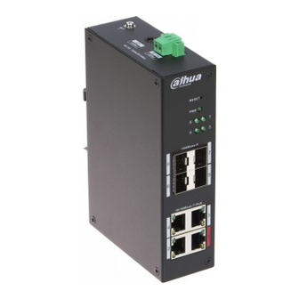
Quick Start Guide 2 Port and Indicator 2.1 Front Panel Front Panel (4-port 100 Mbps) The following figure is for reference only, and might differ from the actual product. Figure 2-1 Front panel (4-port 100 Mbps) Table 2-1 Front panel (4-port 100 Mbps) Description 10/100 Mbps self-adaptive PoE port. - Page 10 Quick Start Guide Description PoE port status indicator. On: Powered by PoE. ● Off: Not powered by PoE. ● Front Panel (8-port 100 Mbps) Figure 2-2 Front panel (8-port 100 Mbps) Table 2-2 Front panel (8-port 100 Mbps) Description 10/100 Mbps self-adaptive PoE port. 1000 Mbps uplink optical port.
- Page 11 Quick Start Guide Description PoE port status indicator. On: Powered by PoE. ● Off: Not powered by PoE. ● Front Panel (4/8-port 1000 Mbps) Figure 2-3 Front panel (4/8-port 1000 Mbps) Table 2-3 Front panel (4/8-port 1000 Mbps) Description 10/100/1000 Mbps self-adaptive PoE port. 10/100/1000 Mbps uplink Ethernet port.
- Page 12 Quick Start Guide Description Data transmission status indicator (Act) for uplink optical port. Flashes: 1000 Mbps data transmission is in progress. ● Off: No data transmission. ● Data transmission status indicator (Act) for Ethernet port. Flashes: 10/100/1000 Mbps data transmission is in progress. ●...
-
Page 13: Side Panel
Quick Start Guide Description Console port. Serial port. Data transmission and connection status indicator (Link/Act) for uplink optical port. On: Connected to device. ● Off: Not connected to device. ● Flashes: Data transmission is in progress. ● 1000 Mbps uplink optical port. Single-port connection or data transmission status indicator (Link/Act). -
Page 14: Din-Rail Mount
Quick Start Guide 3 DIN-rail Mount The device supports DIN-rail mount. Hang the switch hook on the rail, and press the switch to make the buckle latch on to the rail. Different models support dofferent width pf the rail. 4/8-port supports 38 mm and 16-port supports 50 mm. -
Page 15: Wiring
Quick Start Guide 4 Wiring 4.1 Connecting GND Cable Background Information Device GND connection helps ensure device lightning protection and anti-interference. You should connect the GND cable before powering on the device, and power off the device before disconnecting the GND cable. There is a GND screw on the device cover board for the GND cable. It is called enclosure GND. -
Page 16: Connecting Sfp Ethernet Port
Quick Start Guide Figure 4-2 Power terminal Table 4-1 Description of power terminal Description To connect the negative pole. To connect to the positive pole. To connect the power adapter. Procedure Step 1 Connect the device grounding wire. Step 2 Take off the power terminal plug from the device. -
Page 17: Connecting Ethernet Port
Quick Start Guide Do not remove the dust plug of the SFP optical module before connecting the optical ● port. Do not directly insert the SFP optical module with the optical fiber inserted into the ● slot. Unplug the optical fiber before installing it. Figure 4-3 SFP module structure Table 4-2 Description SFP module Name... -
Page 18: Connecting Poe Ethernet Port
Quick Start Guide Figure 4-6 Pin description The cable connection of RJ-45 connector conforms to the standard 568B (1-orange white, 2-orange, 3-green white, 4-blue, 5-blue white, 6-green, 7-brown white, 8-brown). 4.5 Connecting PoE Ethernet Port You can directly connect the device PoE Ethernet port to the switch PoE Ethernet port through network cable to achieve synchronized network connection and power supply. -
Page 19: Initializing And Adding The Device
Quick Start Guide 5 Initializing and Adding the Device 5.1 Initializing the Device You can use DoLynk Care app to scan the QR code of the Device, and then add and initialize the ● Device when the Device is connected to Internet. You can log in to the webpage to initialize the Device and modify the IP address when the ●... - Page 20 Quick Start Guide You can scan the QR code to obtain the SN or manually enter the SN. Figure 5-2 Scan the QR code You need select Switch and select a site, and then tap OK. Step 3 If there is no site, tap , and then select a site.
-
Page 21: Appendix 1 Security Commitment And Recommendation
Dahua employees and provide adequate security for products. Dahua has established a professional security team to provide full life cycle security empowerment and control for product design, development, testing, production, delivery and maintenance. - Page 22 Quick Start Guide Service Configuration 1. Enable HTTPS It is recommended that you enable HTTPS to access Web services through secure channels. 2. Encrypted transmission of audio and video If your audio and video data contents are very important or sensitive, we recommend you to use encrypted transmission function in order to reduce the risk of your audio and video data being eavesdropped during transmission.
- Page 23 Quick Start Guide By viewing logs, you can learn about the IP addresses that attempt to log in to the device and key operations of the logged users. 3. Configure network log Due to the limited storage capacity of devices, the stored log is limited. If you need to save the log for a long time, it is recommended to enable the network log function to ensure that the critical logs are synchronized to the network log server for tracing.
Need help?
Do you have a question about the HS4408-4ET-96 and is the answer not in the manual?
Questions and answers