Table of Contents
Advertisement
Quick Links
Advertisement
Table of Contents

Related Manuals for Dahua PFS4307-4ET-96


Summary of Contents for Dahua PFS4307-4ET-96
- Page 1 Hardened Managed Switch Quick Start Guide V1.0.1...
-
Page 2: Foreword
Foreword General This manual introduces the installation, functions and operations of the hardened managed switch (hereinafter referred to as "the Device"). Read carefully before using the device, and keep the manual safe for future reference. Safety Instructions The following signal words might appear in the manual. Signal Words Meaning Indicates a high potential hazard which, if not avoided, will result in... - Page 3 ● All designs and software are subject to change without prior written notice. Product updates might result in some differences appearing between the actual product and the manual. Please contact customer service for the latest program and supplementary documentation. ● There might be errors in the print or deviations in the description of the functions, operations and technical data.
-
Page 4: Important Safeguards And Warnings
Important Safeguards and Warnings This section introduces content covering the proper handling of the device, hazard prevention, and prevention of property damage. Read carefully before using the device, and comply with the guidelines when using it. Transportation Requirements Transport the device under allowed humidity and temperature conditions. Storage Requirements Store the device under allowed humidity and temperature conditions. - Page 5 Operation Requirements ● Do not disassemble the device without professional instruction. ● Operate the device within the rated range of power input and output. ● Make sure that the power supply is correct before use. ● Make sure the device is powered off before disassembling wires to avoid personal injury ●...
-
Page 6: Table Of Contents
Table of Contents Foreword ........................................I Important Safeguards and Warnings ............................III 1 Overview ........................................1 1.1 Introduction ....................................1 1.2 Features ......................................1 2 Port and Indicator ....................................2 2.1 Front Panel ....................................2 2.2 Side Panel ...................................... 3 3 Installation ....................................... 4 4 Wiring ......................................... -
Page 7: Overview
1 Overview 1.1 Introduction The product is a professional device. The Device is layer-2 hardened switch. Equipped with high performance switching engine and large buffer memory, it features low transmission delay and high reliability. The full-metal and fanless design and efficient surface heat dissipation enable it to work in the environment from –30 °C (–22 °F) to +65 °C (+149°F). -
Page 8: Port And Indicator
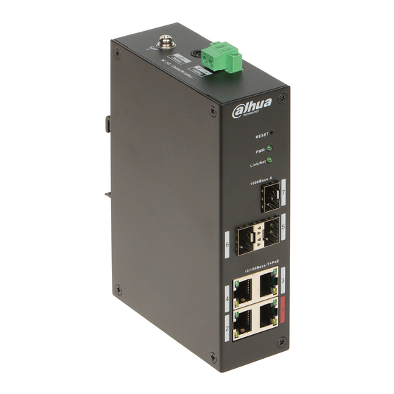
2 Port and Indicator 2.1 Front Panel The following figures are for reference only, and might differ from the actual product. Figure 2-1 Front panel The following are all the ports and indicators on the front panel of the Device. Table 2-1 Description of front panel Description Reset button. -
Page 9: Side Panel
Description Optical-port connection or data transmission status indicator (Link/Act). ● On: Connected to device. ● Off: Not connected to device. ● Flashes: Transmitting 1000 Mbps data. Optical-port connection status indicator (Link). ● On: Connected to device. ● Off: Not connected to device. Optical-port connection or data transmission status indicator (Link/Act). -
Page 10: Installation
3 Installation The Device supports DIN-rail mount. Hang the hook on the rail, press the Device to make the buckle stuck into the rail. The width of the guide rail supported by the Device is 50 mm. Figure 3-1 DIN rail Table 3-1 Component description Description Hook... -
Page 11: Wiring
4 Wiring 4.1 Connecting GND Device GND connection helps ensure device lightning protection and anti-interference. You should connect the GND cable before powering on the Device, and power off the Device before disconnecting the GND cable. There is a GND screw on the Device cover board for the GND cable, which is called enclosure GND. -
Page 12: Connecting Sfp Ethernet Port
To avoid personal injury, do not touch any exposed wire, terminal and areas with danger voltage of the Device and do not dismantle parts or plug connector during power on. Before connecting power, make sure that the power supply conforms to the power supply requirements on the Device label. - Page 13 module is firmly connected to the slot (You can feel that both the top and bottom spring strip of the SFP module are firmly stuck with the SFP slot). Class 1 Laser Product The Device uses laser to transmit signal via optical fiber cable. The laser conforms to the requirements of Class 1 laser products.
-
Page 14: Connecting Ethernet Port
4.4 Connecting Ethernet Port Ethernet port is a standard RJ-45 port. With self-adaptation function, it can be automatically configured to full duplex/half-duplex operation mode. It supports MDI/MDI-X self-recognition of the cable, therefore, you can use cross-over cable or straight-through cable to connect terminal device to network device. -
Page 15: Quick Operation
5 Quick Operation 5.1 Login through Web You can log in to the Device through web for management and operation. For details, see web operation manual. For first login, you need to change the password according to the prompt. Table 5-1 Default factory configuration Parameter Description IP address... -
Page 16: Appendix Cybersecurity Recommendations
Appendix Cybersecurity Recommendations Cybersecurity is more than just a buzzword: it’s something that pertains to every device that is connected to the internet. IP video surveillance is not immune to cyber risks, but taking basic steps toward protecting and strengthening networks and networked appliances will make them less susceptible to attacks. - Page 17 6. Enable HTTPS We suggest you to enable HTTPS, so that you visit Web service through a secure communication channel. 7. MAC Address Binding We recommend you to bind the IP and MAC address of the gateway to the device, thus reducing the risk of ARP spoofing.
Need help?
Do you have a question about the PFS4307-4ET-96 and is the answer not in the manual?
Questions and answers