Advertisement
Quick Links
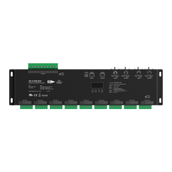
Ultra-Pro 36CH RDM DMX512 Decoder
Important: Read All Instructions Prior to Installation
Function introduction
12-24V DC power input
DC INPUT
13-10AWG
5.5-7.5mm
36 Channels
PHOTOELECTRIC
DMX512 & RDM Decoder
ISOLATION
PRI:
SEC:
Uin=12-24VDC
Uout=36CH x (12-24)VDC
Iin=109A
Iout.Max = 36CHx3A
Pout.Max = 36CHx(36-72)W
TEMP RANGE:-20℃-+50℃
E477171
LED Output 1
LED Output 2
LED Output 3
LED Output 4
R-
G-
B-
W-
R-
G-
B-
W-
R-
G-
B-
W-
R-
G-
V+
V+
V+
V+
V+
V+
V+
V+
1-
2-
3-
4-
1-
2-
3-
4-
1-
2-
3-
4-
1-
2-
4x9=36 channels output
Product Data
Input
Output
Output
Remarks
Voltage
Current
Power
36x(36-72)W
Constant voltage
12-24VDC
36x3A
• Master & decoder mode, RDM function
• Metal housing, digital display to show data directly, easily to set and show DMX address.
• With multiple kinds of DMX in/out ports: RJ 45, XLR3, XLR5 terminal blocks.
• Total 36 PWM output channels, common anode. DMX channel quantity 1CH or 36CH settable.
• PWM output resolution ratio 8bit , 16bit settable.
• Output PWM frequency from 500HZ ~ 35K HZ settable.
• Output dimming curve gamma value from 0.1 ~ 9.9 settable.
• Decoding mode settable.
• Galvanic isolation
Safety & Warnings
• DO NOT install with power applied to device.
• DO NOT expose the device to moisture.
Operation
Before you do other settings, please set the device to be Master or Decoder mode.
= DMX Decoder mode ,
= DMX Master mode(stand alone).
Keep on clicking Down button, to get run1 or run2, then click Enter, then click Down
button to choose 1 or 2, then click Back button.
I. For run2 DMX Master mode: After set the device as run2 (Master mode), if keep on clicking Up button,
you will find below menu on display:
Means brightness for each output PWM channel. First 01 means PWM output channel 1 and it is selectable
from 01 to 36 by clicking "UP" or "Down" button. Second 01 means brightness level, click "Enter" button, the
display flashes, then click "UP" or "Down" button to select from 00-99-FL, which means 0%-99%-100%
brightness, then click "Back" button to confirm.
2xRJ45 terminal:
2xXLR5 terminal:
2xXLR3 terminal:
DMX512 signal
DMX512 signal
DMX512 signal
input & output
input & output
input & output
3
3
12345678
12345678
4
2
2
4
5
1
1
5
DMX Signal
Pin1:GND
DMX Signal
Pin1:GND
DMX Signal
Male
Pin2:D-
Female
Pin2:D-
Male
Pin3:D+
Pin3:D+
DMX IN
DMX OUT
DMX IN
DMX OUT
= DMX Decoder mode
= DMX Master mode(stand alone)
XX
= SET AT CH.36
XX
= 8BIT/16BIT
XX
= PWM FREQUENCY
(00=500HZ thru 35=35kHZ)
XX
= GAMMA CURVE (Default is 1.5)
XX
= SET AT 1.1
LED Output 5
LED Output 6
LED Output 7
LED Output 8
B-
W-
R-
G-
B-
W-
R-
G-
B-
W-
R-
G-
B-
W-
R-
G-
B-
W-
V+
V+
V+
V+
V+
V+
V+
V+
3-
4-
1-
2-
3-
4-
1-
2-
3-
4-
1-
2-
3-
4-
1-
2-
3-
4-
Size(LxWxH)
Protection
393.2x117x37mm
Short circuit
Back Enter
means chasing effects, total 4 effects selectable from 01-04. Click "Up" or "Down" button to select the menu,
then click "Enter" button to enter into the effect, then click "Up" or "Down" button to select from 01-04.
CA01: Fade-up (0%-100%) and fade-down (100%-0%) of output 1, then output 2, output 3, ......, output 36, output 1,
......, cycling chasing
CA02: Fade-up (0%-100%) of output 1, then simultaneous fade-down (100%-0%) of output 1 and fade-up (0%-100%) of
output 2, simultaneous down of output 2 and up of output 3, ......, simultaneous down of output 35 and up of
output 36, simultaneous down of output 36 and up of output 1, ......, cycling chasing
CA03: Fade-up (0%-100%) of output 1, then output 2, output 3, ......, output 36, output 1, ......, cycling chasing
CA04: Fade-down (100%-0%) of output 1, then output 2, output 3, ......, output 36, output 1, ......, cycling chasing
means chasing speed, it selectable from 01-09, 01 is the slowest, 09 is the fastest.
II. For run1 DMX decoder mode: After set the device as run1 (Decoder mode), if keep on clicking Up button,
you will find below menu on display:
DMX signal indicator
3
3
2
1
1
2
on red
XXX
Pin1:GND
DMX Signal
Pin1:GND
Pin2:D-
Female
Pin2:D-
Pin3:D+
Pin3:D+
DMX IN
DMX OUT
you will get this after power on the decoder, it means this decoder supports firmware OTA update function.
XXX
Means DMX address. factory defaults setting is 001.
XX
Means DMX channels quantity. factory defaults setting is CH36
16-12AWG
XX
Means Bit (8bit or 16bit). factory defaults setting is 16bit
5.5-7.5mm
LED Output 9
R-
G-
B-
W-
V+
V+
Means output PWM frequency. factory defaults setting is 10K HZ. PF00=500Hz, PF01=1KHz, PF02=2KHz,
1-
2-
3-
4-
XX
PF03=3KHz,..., PF35=35KHz.
XX
Means output dimming curve gamma value, factory defaults setting is ga 1.5
XX
Means Decoding mode, factory defaults setting is dp1.1
Means the device at run1 mode (DMX decoder mode).
Lock the button:
Under this state there will be no reaction when you play any buttons.
Unlock the button:
Test Mode:
Press and hold down both "Back" and "Up" keys for 3s, the display you show
Under this state, all output channels will light on and off one by one.
Quit Test Mode: Press and hold down both "Back" and "Up" keys for 3s.
Wiring diagram
V
LED Output 1
R-
G-
V+
V+
1-
2-
Up Down
: When DMX signal input is detected, the indicator on the display following after
, if there is no DMX signal input, the indicator will not turn on, and the character
Press and hold down both "Back" and "Down" keys for 3s,the display you show
Press and hold down both "Back" and "Down" keys for 3s.
V+
12V/24V CV PSU
+
V
-
V-
12345678
DC INPUT
13-10AWG
5.5-7.5mm
DMX IN
36 Channels
PHOTOELECTRIC
DMX512 & RDM Decoder
ISOLATION
PRI:
SEC:
Uin=12-24VDC
Uout=36CH x (12-24)VDC
Iin=109A
Iout.Max = 36CHx3A
Pout.Max = 36CHx(36-72)W
TEMP RANGE:-20℃-+50℃
E477171
LED Output 2
LED Output 3
LED Output 4
LED Output 5
B-
W-
R-
G-
B-
W-
R-
G-
B-
W-
R-
G-
B-
W-
R-
G-
B-
W-
V+
V+
V+
V+
V+
V+
V+
V+
V+
3-
4-
1-
2-
3-
4-
1-
2-
3-
4-
1-
2-
3-
4-
1-
2-
3-
4-
turns
will flash.
.
,
DMX512 Signal Input(Under Decoder mode)
DMX512 Signal Out
3
3
3
3
12345678
4
2
2
4
2
1
1
2
5
1
1
5
DMX Signal
Pin1:GND
DMX Signal
Pin1:GND
DMX Signal
Pin1:GND
DMX Signal
Pin1:GND
Male
Pin2:D-
Female
Pin2:D-
Male
Pin2:D-
Female
Pin2:D-
Pin3:D+
Pin3:D+
Pin3:D+
Pin3:D+
DMX OUT
DMX IN
DMX OUT
DMX IN
DMX OUT
= DMX Decoder mode
= DMX Master mode(stand alone)
XX
= SET AT CH.36
XX
= 8BIT/16BIT
XX
= PWM FREQUENCY
(00=500HZ thru 35=35kHZ)
XX
= GAMMA CURVE (Default is 1.5)
XX
= SET AT 1.1
16-12AWG
5.5-7.5mm
LED Output 6
LED Output 7
LED Output 8
LED Output 9
R-
G-
B-
W-
R-
G-
B-
W-
R-
G-
B-
W-
R-
G-
B-
W-
V+
V+
V+
V+
V+
V+
V+
1-
2-
3-
4-
1-
2-
3-
4-
1-
2-
3-
4-
1-
2-
3-
4-
Advertisement

Subscribe to Our Youtube Channel
Related Manuals for Sunricher SR-2108B-M36


Summary of Contents for Sunricher SR-2108B-M36
- Page 1 Ultra-Pro 36CH RDM DMX512 Decoder means chasing effects, total 4 effects selectable from 01-04. Click “Up” or “Down” button to select the menu, then click “Enter” button to enter into the effect, then click “Up” or “Down” button to select from 01-04. CA01: Fade-up (0%-100%) and fade-down (100%-0%) of output 1, then output 2, output 3, ……, output 36, output 1, ……, cycling chasing Important: Read All Instructions Prior to Installation...
- Page 2 1. DMX address setting: 6. DMX decoding mode setting: Select menu , click button “Enter”, display flashes,then click or hold button “Up” / “Down” to set DMX address Select menu , click button “Enter”, display flashes, then click button “Up” / “Down” to choose the decoding mode, (click is slow, hold is fast.), then click button“Back”...
- Page 3 Slider 1= Address 001, 002 master dimming, Slider 2= Address 001 dimming, Slider 1= Address 001-003 master dimming, Slider 2= Address 001 dimming, dp3.2 dp4.3 Use 3 console sliders to control 2 DMX addresses Use 4 console sliders to control 3 DMX addresses Slider 3= Address 002 dimming,..., Slider 9= Address 006 dimming Slider 3= Address 002 dimming, Slider 4= Address 003 dimming.
Need help?
Do you have a question about the SR-2108B-M36 and is the answer not in the manual?
Questions and answers