Table of Contents
Advertisement
Advertisement
Table of Contents

Related Manuals for TP-Link Omada ER8411


Summary of Contents for TP-Link Omada ER8411
- Page 1 Business Networking Solution Installation Guide Omada VPN Router...
- Page 2 Remind to take notice. The note contains the helpful information for a better use of the product. Related Document The User Guide of the product are provided on Download Center. To obtain the latest product information, visit the official website: https://www.tp-link.com.
-
Page 3: Table Of Contents
Contents Chapter 1 Appearance ——————————— 01 Front Panel .................01 Rear Panel ................04 Chapter 2 Installation ——————————— 05 Package Contents ............05 Safety Precautions ............05 Installation Tools ..............07 Product Installation ............07 Chapter 3 Hardware Connection —————— 09 Chapter 4 Software Configuration —————— 10 Appendix A Troubleshooting ————————... -
Page 4: Appearance
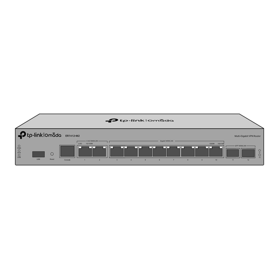
Omada VPN Router Chapter 1 Appearance Front Panel The figures are for demonstration only. They may differ from your actual products. The front panel of ER7412-M2 is shown as the following figure. ■ Indication On: The router is powered on. Off: The router is powered off or power supply is abnormal. - Page 5 Omada VPN Router Interface Description USB 3.0 port for USB modem and USB storage device. Press and hold the button for 5 seconds, the SYS LED will flash quickly, indicating the Reset device is being reset to its factory default settings. Console Connect with a computer for monitoring and configuring the router.
- Page 6 Omada VPN Router Indication For USB Modem: Flashing: A modem is connected and it is initializing. On: The modem is loaded. Off: No modem is inserted, or it is corrupted or incompatible. For USB Storage: On: A USB storage device is inserted and identified. Off: No USB storage device is inserted, or it is corrupted or incompatible.
-
Page 7: Rear Panel
PE (Protecting Earth) cable of AC cord or with Ground Cable. For detailed lightning protection measures, go to https://www.tp-link.com/support, search the model number of your device and go to the product Support web page, refer to the Lightning Protection Guide from the Related Documents: https://www.tp-link.com/us/configuration-guides/lightning_protection_guide/. -
Page 8: Chapter 2 Installation
Omada VPN Router Chapter 2 Installation Package Contents Make sure that the package contains the following items. Please contact your distributor, if any of the listed items is damaged or missing. The figures are for demonstration only. The actual items may differ in appearance and quantity from the depicted. Power Cord and Console Router Cable... - Page 9 Omada VPN Router Keep the equipment room at an appropriate level of temperature and humidity. Too much or too little humidity may lead to bad insulation, leakage of electricity, mechanical property changes, and corrosion. High temperatures may accelerate aging of the insulation materials, significantly shortening the service life of the device.
-
Page 10: Installation Tools
Use the signal SPD (Surge Protective Device) when wiring outdoor. ■ Note: For detailed lightning protection measures, go to https://www.tp-link.com/support, search the model number of your device and go to the product Support web page, refer to the Lightning Protection Guide from the Related Documents: https://www.tp-link.com/us/configuration-guides/lightning_protection_guide/. - Page 11 Omada VPN Router Figure 2-1 Desktop Installation Feet Bottom of the Device Notch Rack Installation ■ To install the device in a rack, follow the instructions described below: 1. Check the efficiency of the grounding system and the stability of the rack. 2.
-
Page 12: Chapter 3 Hardware Connection
Omada VPN Router Chapter 3 Hardware Connection Follow the steps below to connect your router to the internet. Connect via Ethernet Modem Internet Connect to RJ45 WAN Port Connect via fiber network Internet Connect to SFP/SFP+ WAN Slot Fiber-Optic Cable SFP/SFP+ Module Note: 1. -
Page 13: Chapter 4 Software Configuration
Make sure the ports you select as WAN ports correspond to the real situation. For the detailed configurations, refer to the User Guide and CLI Guide. The guides can be found on the download center of our official website: https://www.tp-link.com/support/download/. Controller Mode ■... - Page 14 Launch a web browser and enter https://omada.tplinkcloud.com in the address bar. Enter your TP-Link ID and password to log in. Click + Add Controller and choose Hardware Controller to add your controller. Then you can further configure the controller.
- Page 15 After installing Omada Software Controller, you can remotely access the controller through Omada Cloud Portal. Follow the steps below. a. Enable Cloud Access on the setting page on the controller and bind a TP-Link ID to your controller. If you have configured this in the setup wizard, skip the step.
- Page 16 Omada VPN Router c. Enter your TP-Link ID and password to log in. A list of controllers that have been bound with your TP-Link ID will appear. Then you can click Launch to further configure the controller. For the detailed configurations, refer to the User Guide of the controller. The guide can be found on the download center of our official website: https://www.tp-link.com/support/download/.
-
Page 17: Appendix A Troubleshooting
Omada VPN Router Appendix A Troubleshooting Q1. What should I do if I want to change the mode of the WAN/LAN ports? Recommended) Refer to the Interface Description table of this guide for the default mode of the WAN/LAN ports. Connect a computer to a LAN port of this router. -
Page 18: Appendix B Specifications
Omada VPN Router Appendix B Specifications Specifications for routers with RJ45 Ports and SFP/SFP+ Slots Item Content IEEE 802.3, IEEE 802.3u, IEEE 802.3ab, IEEE 802.3ad, IEEE 802.3z, Standards IEEE 802.3x, IEEE 802.1p, IEEE 802.1q, IEEE 802.1x, IEEE 802.1d, IEEE 802.1s, IEEE 802.1w, IEEE 802.1ab 10BASE-T: 2-pair UTP/STP of Cat. 3,4,5 (maximum 100 m) 100BASE-TX: 2-pair UTP/STP of Cat. - Page 19 EU Declaration of Conformity TP-Link hereby declares that the device is in compliance with the essential requirements and other relevant provisions of directives 2014/30/EU, 2014/35/EU, 2011/65/EU and (EU)2015/863. The original EU Declaration of Conformity may be found at https://www.tp-link.com/en/support/ce/...
- Page 20 To ask questions, find answers, and communicate with TP-Link users or engineers, please visit https://community.tp-link.com to join TP-Link Community. For technical support, the user guide and other information, please visit https://www.tp-link.com/support, or simply scan the QR code. © 2023 TP-Link 7106510771 REV1.0.1...
Need help?
Do you have a question about the Omada ER8411 and is the answer not in the manual?
Questions and answers