Table of Contents
Advertisement
Quick Links
Advertisement
Table of Contents

Subscribe to Our Youtube Channel
Related Manuals for DFI CS100-C246


Summary of Contents for DFI CS100-C246
- Page 1 CS100-Q370/C246/H310 Mini-ITX Industrial Motherboard User’s Manual A50800917...
-
Page 2: Copyright
Copyright FCC and DOC Statement on Class B This publication contains information that is protected by copyright. No part of it may be re- This equipment has been tested and found to comply with the limits for a Class B digital produced in any form or by any means or used to make any transformation/adaptation without device, pursuant to Part 15 of the FCC rules. -
Page 3: Table Of Contents
Table of Contents I/O Connectors ................... 23 SATA (Serial ATA) Connectors ..............23 Digital I/O Connector .................. 23 Digital I/O Power Connector ................ 23 Cooling Fan Connectors................24 Copyright ......................2 Power Connectors ..................24 LVDS LCD Panel Connector ................. 25 Trademarks ...................... -
Page 4: Warranty
Warranty Static Electricity Precautions 1. Warranty does not cover damages or failures that arised from misuse of the product, in- It is quite easy to inadvertently damage your PC, system board, components or devices even ability to use the product, unauthorized replacement or alteration of components and prod- before installing them in your system unit. -
Page 5: About The Package
About the Package The package contains the following items. If any of these items are missing or damaged, please contact your dealer or sales representative for assistance. • One CS100-Q370/C246/H310 motherboard • One COM port cable (Length: 250mm, 1 x COM port) •... -
Page 6: Chapter 1 - Introduction
Chapter 1 Chapter 1 - Introduction Specifications SYSTEM Processor 8th Generation Intel ® Core™ Processors, LGA 1151 Socket, TDP up to 80W INTERNAL I/O Serial 1 x RS-232 (RS-232 w/ power) (2.0mm pitch) Intel ® Xeon E-2176G Processor (support ECC Memory) Display 1 x LVDS LCD Panel Connector ®... -
Page 7: Features
Chapter 1 Features • Wake-On-LAN • Watchdog Timer This feature allows the network to remotely wake up a Soft Power Down (Soft-Off) PC. It is supported via the onboard LAN port or via a PCI LAN card that uses the PCI PME (Power Man- The Watchdog Timer function allows your application to regularly “clear”... - Page 8 Chapter 1 • Power Failure Recovery When power returns after an AC power failure, you may choose to either power-on the system manually or let the system power-on automatically. • USB The CS100-Q370/C246 supports the new USB 3.1 Gen2 and CS100-H310 supports the USB 3.1 Gen1.
-
Page 9: Chapter 2 - Hardware Installation
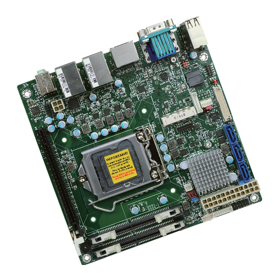
Chapter 2 Chapter 2 - Hardware Installation Board Layout Panel Mini PCIe/mSATA Select (JP2) Power (CS100-Q370/C246 only) Select Chassis SATA 3.0 (JP8) LVDS LCD Panel Intrusion COM 2 SATA 2 SATA 1 SATA 0 USB 2.0 LCD/Inverter Power SPI Flash BIOS Select (JP9) USB 7,8,9,14 PTN3460... -
Page 10: Block Diagram
Chapter 2 Block Diagram Important: Electrostatic discharge (ESD) can damage your board, processor, disk drives, add-in boards, and other components. Perform installation procedures at an ESD workstation only. If such a station is not available, you can provide some ESD protection by wear- ing an antistatic wrist strap and attaching it to a metal part of the system chassis. -
Page 11: Installing The Sodimm Module
Chapter 2 The system board supports the following memory interface. Installing the SODIMM Module Note: Single Channel (SC) The system board used in the following illustrations may not resemble the actual Data will be accessed in chunks of 64 bits from the memory channels. board. -
Page 12: Cpu
Chapter 2 6. Grasping the module by its edges, position the module above the socket with the “notch” in the module aligned with the “key” on the socket. The keying mechanism ensures the module can be plugged into the socket in only one way. The system board is equipped with a surface mount LGA 1151 socket. -
Page 13: Installing The Cpu
Chapter 2 Load lever Installing the CPU 5. Lifting the load lever will at the same time lift the load plate. 1. Make sure the PC and all other peripheral devices connected to it has been powered down. Lift the load lever up to 2. - Page 14 Chapter 2 7. Insert the CPU into the 8. Close the load plate then socket. The gold triangular push the load lever down. mark on the CPU must align with the corner of While closing the load Retention knob the CPU socket shown on plate, make sure the front the photo.
-
Page 15: Installing The Fan And Heat Sink
Chapter 2 Installing the Fan and Heat Sink 4. Rotate each screw that are diagonally across the heat sink. Perform the same The CPU must be kept cool by using a CPU fan with heat sink. Without sufficient air circula- procedure for the other tion across the CPU and heat sink, the CPU will overheat damaging both the CPU and system board. -
Page 16: Jumper Settings
Chapter 2 Jumper Settings Backlight Brightness Select Clear CMOS 1-2 On: 1-2 On: +3.3V (default) Normal (default) 2-3 On: 2-3 On: Clear CMOS If you encounter the followings, JP7 is used to select the power level of backlight brightness control: +3.3V (default) or +5V. a) CMOS data becomes corrupted. -
Page 17: Com 2 Rs232/Power Select
Chapter 2 COM 2 RS232/Power Select 5 3 1 5 3 1 6 4 2 6 4 2 1-3 (RI-), 2-4 (DCD-) On: 3-5 (+5V), 4-6 (+12V) On: RS232 (default) RS232 with power COM 2 COM 2 RS232 RS232 with power DCD- +12V SIN-... -
Page 18: Lcd/Inverter Power Select
Chapter 2 LCD/Inverter Power Select Panel Power Select 1-2 On: 1-2 On: +12V +12V (default) 2-3 On: 3-4 On: +5V 5-6 On: +3.3V (default) JP8 is used to select the power supplied with the LCD panel. JP9 is used to select the power level of LVDS LCD inverter connector. Important: Before powering-on the system, make sure that the power settings of JP8 match the LCD panel’s specification. -
Page 19: Mini Pcie/Msata Signal Select (Cs100-Q370/C246 Only)
Chapter 2 Mini PCIe/mSATA Signal Select (CS100-Q370/C246 only) 1-2 On: Mini PCIe (default) 2-3 On: mSATA JP2 is used to select the Mini PCIe signal. Chapter 2 Hardware Installation www.dfi .com... -
Page 20: Rear Panel I/O Ports
Chapter 2 Rear Panel I/O Ports RJ45 LAN Ports LAN 1 LAN 2 COM 1 LAN 1 LAN 2 Line-in (optional) Line-out Mic-in CS100-H310 DP++*2 USB 2.0*4 USB 3.1 Gen1*4 LAN 1 LAN 2 LAN 1 LAN 2 CS100-H310 COM 1 LAN 1 LAN 2 Line-in (optional) -
Page 21: Usb Ports
Chapter 2 USB Ports Graphics Interfaces The display ports consist of the following: USB 9 • 1 VGA port USB 14 • 2 DP++ ports USB 7 USB 8 USB 2.0 USB 4 USB 2 USB 3 USB 1 USB 3.1 Gen1 USB 3.1 Gen1 DP++ CS100-H310... -
Page 22: Com (Serial) Ports
Chapter 2 COM (Serial) Ports Audio 1 2 3 4 5 Line-in (optional) Line-out 6 7 8 9 Mic-in COM 1: RS232 Rear Audio COM 2: RS232 Front Audio Rear Audio COM 1 and COM 2 are fixed at RS232. Please refer pin functions of COM 1 above. The system board is equipped with 2 audio jacks (Line-out and Mic-in). -
Page 23: I/O Connectors
Chapter 2 I/O Connectors Digital I/O Connector Digital I/O Power Connector SATA (Serial ATA) Connectors SATA 3.0 6Gb/s SATA 2 SATA 1 SATA 0 Digital I/O Digital I/O Power +12V Ground 5VDU The 8-bit Digital I/O connector provides powering-on function to external devices that are con- Features nected to these connectors. -
Page 24: Cooling Fan Connectors
Chapter 2 Cooling Fan Connectors Power Connectors 12 24 Speed Control +3.3V ATX power CPU Fan Sense +12V +12V Ground +5VSB PWR_OK PS_ON# +3.3V -12V +3.3V +3.3V Sense +12V Power ystem Fan 1 Ground Ground +12V +12V Ground The fan connectors are used to connect cooling fans. The cooling fans will provide adequate airflow throughout the chassis to prevent overheating the CPU and system board components. -
Page 25: Lvds Lcd Panel Connector
Panel Power Panel Power Panel Power Note: 1. LVDS LCD Panel Connector (DFI PN: 346-714000-204G) Description: WTB HEADER 40P, 1.25mm, M,H=4.8mm, 180D, SMT, BEIGE, 712-76-40GWE0 (PRINEX) RoHS 2. LCD/Inverter Power Connector (DFI PN: 346-510801-100G) Description: BOX HEADER 1*8, 8P/2.0mm/180D, 721-81-08TW00(PINREX)RoHS Chapter 2 Hardware Installation www.dfi... -
Page 26: Chassis Intrusion Connector
Chapter 2 Chassis Intrusion Connector Front Panel Connector Front Chassis Panel Signal Intrusion Ground PWR-LED HD-LED ATX-SW RESET HD-LED - Hard Drive LED This LED will light when the hard drive is being accessed. The board supports the chassis intrusion detection function. Connect the chassis intrusion sensor cable from the chassis to this connector. -
Page 27: Expansion Slots
Chapter 2 Expansion Slots S/PDIF Connector Mini PCI Express & mSATA (CS100-Q370/CS246) mSATA (CS100-H310) PCI Express x16 S/PDIF Mini PCI Express Slot The S/PDIF connector is used to connect an external S/PDIF port. Your S/PDIF port may be The full-size Mini PCIe socket supports the installation of a Mini PCIe card or an mSATA card. mounted on a card-edge bracket. -
Page 28: Lpc Connector
LPC Connector Connecting the EXT-RS232/RS485 Card to the Motherboard With DFI’s proprietary technology, CS100-Q370/C246/H310 supports two extension modules for additional four COM ports. The EXT-RS232/RS485 card is connected to CS100-Q370/C246/H310 via the LPC connector. The illustrations below guide you how to connect the extension module to 14 13 the motherboard. -
Page 29: Battery
Chapter 2 Battery Battery Connector +3.3V Connect to the battery connector Battery The lithium ion battery powers the real-time clock and CMOS memory. It is an auxiliary source of power when the main power is shut off. Safety Measures • Danger of explosion if battery incorrectly replaced. •... -
Page 30: Chapter 3 - Bios Setup
Chapter 3 Chapter 3 - BIOS Setup Legends Overview Keys Function The BIOS is a program that takes care of the basic level of communication between the CPU and peripherals. It contains codes for various advanced features found in this system board. Right and Left arrows Moves the highlight left or right to select a menu. -
Page 31: Ami Bios Setup Utility
Chapter 3 AMI BIOS Setup Utility Aptio Setup Utility - Copyright (C) 2019 American Megatrends, Inc. Main Advanced Chipset Security Boot Save & Exit Main BIOS Version B194.01A Set the Time. Use Tab to switch between Time FSP version 07.00.56.50 elements. -
Page 32: Advanced
Chapter 3 Advanced RC ACPI Settings The Advanced menu allows you to configure your system for basic operation. Some entries are This section is used to configure the system ACPI parameters. defaults required by the system board, while others, if enabled, will improve the performance of your system or let you set some features according to your preference. - Page 33 Chapter 3 CPU Configuration Aptio Setup Utility - Copyright (C) 2019 American Megatrends, Inc. Advanced This section is used to configure the CPU. RC ACPI Settings select 0-23 For example enter 3 for 3am and 15 [Enabled] Wake System from S5 via RTC for 3pm Aptio Setup Utility - Copyright (C) 2019 American Megatrends, Inc.
- Page 34 Chapter 3 Power & Performance PCH-FW Configuration This section is used to configure the power & performance options. This section configures the parameters of Management Engine Technology. Aptio Setup Utility - Copyright (C) 2019 American Megatrends, Inc. Aptio Setup Utility - Copyright (C) 2019 American Megatrends, Inc. Advanced Advanced Power &...
- Page 35 Chapter 3 Aptio Setup Utility - Copyright (C) 2019 American Megatrends, Inc. Aptio Setup Utility - Copyright (C) 2019 American Megatrends, Inc. Advanced Advanced ME State [Enabled] Confi gure Intel(R) Active Secure Erase mode [Simulated] Change Secure Erase Manageability Features State [Enabled] Management Technology Force Secure Erase...
- Page 36 Chapter 3 Aptio Setup Utility - Copyright (C) 2019 American Megatrends, Inc. Aptio Setup Utility - Copyright (C) 2019 American Megatrends, Inc. Advanced Advanced Hide Unconfi gure ME Confi rmation [Disabled] OEMFlag Bit 6: ME State [Enabled] Confi gure Management Prompt Hide Unconfi...
- Page 37 Chapter 3 Trusted Computing PTN3460 Configuration This section configures settings relevant to Trusted Computing innovations. This section is used to configure the PTN3460 Parameters. Aptio Setup Utility - Copyright (C) 2019 American Megatrends, Inc. Aptio Setup Utility - Copyright (C) 2019 American Megatrends, Inc. Advanced Advanced TPM20 Device Found...
- Page 38 Chapter 3 Serial Port NCT6106D Super IO Configuration Enable or disable the serial COM port. This section is used to configure the I/O functions supported by the onboard Super I/O chip. Aptio Setup Utility - Copyright (C) 2019 American Megatrends, Inc. Advanced WatchDog Timer Unit NCT6106D Super IO Confi...
- Page 39 Chapter 3 NCT6106D HW Monitor CPU Smart Fan/System Smart Fan(1) Control This section displays the hardware health monitor and also configures smart fan and case Enable or disable the CPU smart fan/system smart fan(1). open functions. Boundary 1 to Boundary 4 Aptio Setup Utility - Copyright (C) 2019 American Megatrends, Inc.
- Page 40 Chapter 3 Serial Port Console Redirection Aptio Setup Utility - Copyright (C) 2019 American Megatrends, Inc. Advanced This section configures settings relevant to serial port console redirection. COM1 Emulation: ANSI: Console Redirection Settings Extended ASCII char set. VT100: ASCII char set. Aptio Setup Utility - Copyright (C) 2019 American Megatrends, Inc.
- Page 41 Chapter 3 CSM Configuration USB Configuration This section is used to configure the CSM settings. This section is used to configure the USB settings. Aptio Setup Utility - Copyright (C) 2019 American Megatrends, Inc. Aptio Setup Utility - Copyright (C) 2019 American Megatrends, Inc. Advanced Advanced USB Confi...
- Page 42 Chapter 3 Network Stack Configuration Boot option filter This section is used to configure the Network Stack settings. This field controls Legacy/UEFI ROMs priority. Aptio Setup Utility - Copyright (C) 2019 American Megatrends, Inc. Network Advanced This field controls the execution of UEFI and Legacy Network OpROM. Network Stack [Disabled] Enable/Disable UEFI...
-
Page 43: Chipset
Chapter 3 Chipset Ipv4 PXE Support Enable or disable IPv4 PXE boot support. If disabled, IPv4 PXE boot support will not This section configures relevant chipset functions. be available. Ipv6 PXE Support Aptio Setup Utility - Copyright (C) 2019 American Megatrends, Inc. Main Advanced Chipset... - Page 44 Chapter 3 PEG Port Configuration PCH-IO Configuration This section configures the PEG port. This section configures the PCH parameters. Aptio Setup Utility - Copyright (C) 2019 American Megatrends, Inc. Aptio Setup Utility - Copyright (C) 2019 American Megatrends, Inc. Chipset Chipset PEG Port Confi...
- Page 45 Chapter 3 Aptio Setup Utility - Copyright (C) 2019 American Megatrends, Inc. Aptio Setup Utility - Copyright (C) 2019 American Megatrends, Inc. Chipset Chipset Contol the PCI Express PCI Express Confi guration PCI Express Root Port Mini PCIE [Enabled] Settings. Hot Plug [Disabled] Root Port.
- Page 46 Chapter 3 Aptio Setup Utility - Copyright (C) 2019 American Megatrends, Inc. Aptio Setup Utility - Copyright (C) 2019 American Megatrends, Inc. Chipset Chipset Control Detection of the SATA And RST Confi guration Enable/Disable SATA HD Audio Subsystem Confi guration Settings Device.
-
Page 47: Security
Chapter 3 Security Boot Aptio Setup Utility - Copyright (C) 2019 American Megatrends, Inc. Aptio Setup Utility - Copyright (C) 2019 American Megatrends, Inc. Main Advanced Chipset Security Boot Save & Exit Main Advanced Chipset Security Save & Exit Boot Set Administrator Password Description Password... -
Page 48: Save & Exit
Chapter 3 Save & Exit Note: If "Boot option filter" is set to "UEFI and Legacy" or "UEFI only" and "Quiet Boot" is set to enabled, "BGRT Logo" will show up for configuration. Refer to the Aptio Setup Utility - Copyright (C) 2019 American Megatrends, Inc. Advanced >... -
Page 49: Updaing The Bios
You may refer to how-to-video, How to the safety concerns, the BIOS (SPI ROM) chip cannot be removed from this system board update AMI BIOS in UEFI mode on DFI products?, at https://www.dfi.com/Knowledge/Video/5 and used on another system board of the same model. -
Page 50: Chapter 4 - Supported Software
Please download drivers, utilities and software applications required to enhance the perfor- tion tips then click “Install”. mance of the system board at https://www.dfi.com/product/index/1410#download . Intel Chipset Software Installation Utility The Intel Chipset Software Installation Utility is used for updating Windows ®... - Page 51 Chapter 4 Intel Graphics Driver 3. Go through the readme document for system re- quirements and installation To install the driver, download “CS100 Graphics Driver” zip file at our website. tips then click “Next”. 1. Setup is now ready to install the graphics driver.
- Page 52 Chapter 4 Audio Driver Intel LAN Driver To install the driver, download “CS100 Audio Driver” zip file at our website. To install the driver, download “CS100 LAN Driver” zip file at our website. 1. Setup is ready to install the 1.
- Page 53 Chapter 4 Intel Management Engine Interface Drivers 4. Click “Install” to begin the installation. To install the driver, download “CS100 MEI Driver” zip file at our website. 1. Setup is ready to install the driver. Click “Next”. 5. The step displays the installing status in the prog- ress.
- Page 54 Chapter 4 SIO Driver 3. Click “Next” to install to the default folder, or click “Change” to choose another To install the driver, download “CS100 SIO Driver” zip file at our website. destination folder. 1. Setup is ready to install the driver. Click “Next”.
- Page 55 Chapter 4 5. Setup is now installing the 3. Go through the readme docu- driver. ment for system requirements and installation tips then click “Next”. 4. Setup is ready to install the driver. 6. Click “Yes, I want to restart Click “Next”.
- Page 56 Chapter 4 Intel Rapid Storage Technology 3. Go through the readme document to view system requirements and installa- The Intel Rapid Storage Technology is a utility that allows you to monitor the current status tion information then click of the SATA drives. It enables enhanced performance and power management for the storage “Next”.
- Page 57 Chapter 4 6. Click “Yes, I want to restart this computer now” to complete the installation and then click “Finish”. Chapter 4 Supported Software www.dfi .com...
-
Page 58: Chapter 5 - Raid (Cs100-Q370/C246 Only)
Chapter 5 Chapter 5 - RAID (CS100-Q370/C246 Only) Settings The system board allows configuring RAID on Serial ATA drives. It supports RAID 0, RAID 1, and RAID 5. To enable the RAID function, the following settings are required. RAID Levels 1. - Page 59 Chapter 5 Step 3: Create a RAID Volume Step 4: Install the Intel Rapid Storage Technology Utility 1. Go to the “Advanced” menu of the AMI BIOS and select “Intel(R) Rapid Storage Technol- The Intel Rapid Storage Technology Utility can be installed from within Windows. It allows ogy”.
-
Page 60: Chapter 6 - Intel Amt Settings (Cs100-Q370/C246 Only)
Chapter 6 Chapter 6 - Intel AMT Settings (CS100-Q370/C246 only) Enable Intel AMT in the AMI BIOS ® Overview 1. Power-on the system then press <Del> to enter the main menu of the AMI BIOS. Intel Active Management Technology (Intel ®... - Page 61 Chapter 6 4. In the Save & Exit menu, select Save Changes and Reset and then press <Enter>. Configure Intel AMT in the Intel Management Engine BIOS ® ® A dialog box will appear. Select Yes and press Enter to reset the system after saving all changes made.
- Page 62 Chapter 6 2. Select MEBx Login and press Enter. You will be prompted for a password. The default 4. You will be asked to verify the new password. Enter the same new password in the space password is “admin”. Enter the default password in the space provided under Intel(R) ME provided under Verify Password then press Enter.
- Page 63 Chapter 6 6. If you want to change ME password, select Change ME Password then press Enter. 8. You will be asked to verify the new password. Enter the same new password in the space Enter the current password in the space provided under Intel(R) ME Password then press provided under Verify Password then press Enter.
- Page 64 Chapter 6 Press Esc until you return to the Main Menu. Select Intel(R) AMT then press Enter. In the Intel(R) AMT Configuration menu, select Manageability Feature Selection Select Enabled or Disabled then press Enter. then press Enter. Select Enabled or Disabled then press Enter. Intel(R) Management Engine BIOS Extension v12.0.0.0010/Intel(R) ME v12.0.34.1425 Intel(R) Management Engine BIOS Extension v12.0.0.0010/Intel(R) ME v12.0.34.1425 Copyright(C) 2003-17 Intel Corporation.
- Page 65 Chapter 6 Select SOL then press Enter. Select Enabled or Disabled then press Enter. Select KVM Feature Selection then press Enter. Select Enabled or Disabled then press Enter. Intel(R) Management Engine BIOS Extension v12.0.0.0010/Intel(R) ME v12.0.34.1425 Intel(R) Management Engine BIOS Extension v12.0.0.0010/Intel(R) ME v12.0.34.1425 Copyright(C) 2003-17 Intel Corporation.
- Page 66 Chapter 6 In the User Consent menu, select User Opt-in then press Enter. Select NONE or KVM Press Esc until you return to the Intel(R) AMT Configuration menu. Select Password or ALL then press Enter. Policy then press Enter. You may choose to use a password only during setup and configuration or to use a pass- word anytime the system is being accessed.
- Page 67 Chapter 6 In the Intel(R) ME Network Setup menu, select Intel(R) ME Network Name Set- Select Domain Name then press Enter. Enter the computer’s domain name then press tings then press Enter. Enter. Intel(R) Management Engine BIOS Extension v12.0.0.0010/Intel(R) ME v12.0.34.1425 Intel(R) Management Engine BIOS Extension v12.0.0.0010/Intel(R) ME v12.0.34.1425 Copyright(C) 2003-17 Intel Corporation.
- Page 68 Chapter 6 Select Dynamic DNS Update then press Enter. Select Enabled or Disabled then press Select TTL then press Enter. Enter value then press Enter. Enter. If Dynamic DNS Update is set to Enabled, Periodic Update Interval and TTL fields will show up. Intel(R) Management Engine BIOS Extension v12.0.0.0010/Intel(R) ME v12.0.34.1425 Intel(R) Management Engine BIOS Extension v12.0.0.0010/Intel(R) ME v12.0.34.1425 Copyright(C) 2003-17 Intel Corporation.
- Page 69 Chapter 6 In the Wired LAN IPV4 Configuration menu, select DHCP Mode then press Enter. Select Subnet Mask Address then press Enter. Enter address then press Enter. Select Enabled or Disabled then press Enter. If set to Disabled, IPV4 Address, Subnet Mask Address, Default Gateway Address, Preferred DNS Address and Alternate DNS Address will show up.
- Page 70 Chapter 6 Select Preferred DNS Address then press Enter. Enter address then press Enter. Press Esc until you return to the Intel(R) AMT Configuration menu. If you want to activate the current network settings and open the ME network inferface, select Activate Network Access, press Enter, then press Y.
- Page 71 Chapter 6 In the Intel(R) AMT Configuration menu, select Remote Setup And Configuration In the Intel(R) Remote Setup And Configuration menu, select Provisioning Re- then press Enter. cord then press Enter. Intel(R) Management Engine BIOS Extension v12.0.0.0010/Intel(R) ME v12.0.34.1425 Intel(R) Management Engine BIOS Extension v12.0.0.0010/Intel(R) ME v12.0.34.1425 Copyright(C) 2003-17 Intel Corporation.
- Page 72 Chapter 6 In the Intel(R) Remote Setup And Configuration menu, select Provisioning Press Esc until you return to the Intel(R) Remote Setup And Configuration menu. Server FQDN then press Enter. Enter the FQDN then press Enter. Select TLS PKI then press Enter. Select Remote Configuration ** then press Enter. Select Enabled or Disabled then press Enter.
- Page 73 Chapter 6 In the Intel(R) Remote Configuration menu, select Manage Hashes then press In the Intel(R) AMT Power Control menu, select Idle Timeout then press Enter. Enter. Select the hash name then press Insert to enter custom hash certificate name, Enter the timeout value and press Enter.
Need help?
Do you have a question about the CS100-C246 and is the answer not in the manual?
Questions and answers