Table of Contents
Advertisement
Quick Links
Advertisement
Table of Contents

Related Manuals for DFI CS181


Summary of Contents for DFI CS181
- Page 1 CS181 Mini-ITX Industrial Motherboard User’s Manual ver.A_MP_3-1521_13-13...
- Page 2 1. The changes or modifications not expressly approved by the party responsible for com- pliance could void the user’s authority to operate the equipment. 2. Shielded interface cables must be used in order to comply with the emission limits. User's Manual | CS181...
-
Page 3: Table Of Contents
RC ACPI Configuration ....................34 CPU Configuration ......................34 Power & Performance ....................35 PCH-FW Configuration ....................35 Trusted Computing ......................38 NCT5525D Super IO Configuration ................39 NCT5525D HW Monitor ....................40 Serial Port Console Redirection ...................41 USB Configuration ......................42 Network Stack Configuration..................43 User's Manual | CS181... - Page 4 • To reduce the risk of electric shock, unplug the power cord before removing the sys- tem chassis cover for installation or servicing. After installation or servicing, cover the system chassis before plugging the power cord. User's Manual | CS181...
- Page 5 Before Using the System Board When installing the system board in a new system, you will need at least the following internal components. User's Manual | CS181...
-
Page 6: Chapter 1 - Introduction
1 x M.2 2230 E Key (USB2.0/PCIe x1 Gen2) (support BT/Wi-Fi module) Audio Audio Codec Realtek ALC888S-VD2-GR ® ® Ethernet Controller Q370: 1 x Intel I219LM PHY (10/100/1000Mbps) / H310: 1 x Intel I219V PHY (10/100/1000Mbps) ® 3 x Intel I210IT PCIe (10/100/1000Mbps) User's Manual | CS181... - Page 7 Storage: 5 to 90% RH MTBF CS181-Q370 : 538,449 hrs @ 25°C; 324,118 hrs @ 45°C ; 213,302 hrs @ 60°C CS181-H310 : 538,449 hrs @ 25°C; 324,118 hrs @ 45°C ; 213,302 hrs @ 60°C Calculation model: Telcordia Issue 4, GB, GC – Ground Benign, Controlled...
-
Page 8: Features
Event) signal. However, if your system is in the Suspend mode, you can power-on the system only through an IRQ or DMA interrupt. Wake-On-USB This function allows you to use a USB keyboard or USB mouse to wake up a system from the S3 (STR - Suspend To RAM) state. User's Manual | CS181... -
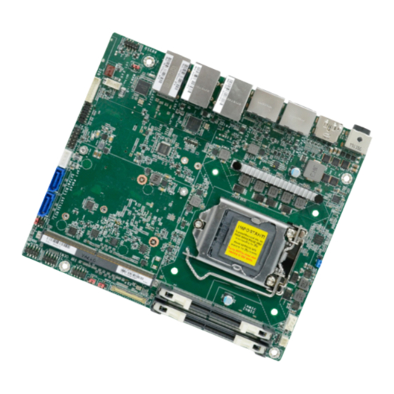
Page 9: Chapter 2 - Hardware Installation
ESD protection. DP_HDMI DPA/DPB DPC/DPD USB3_1/2 USB2_1/2 CN59.G3 USB3_3/4 DPJP202 USB2_3/4 LAN2 DPJP203 LAN3/4 M2JP204 MXM3.1-B DIO Power SYS_FAN CN59.G4 Front Panel DPJP201 SATA0(R3) SATA1(R2) MADE IN TAIWAN User's Manual | CS181... -
Page 10: System Memory
Data will be accessed in chunks of 128 bits from the memory channels. Dual channel provides better system performance because it doubles the data transfer rate. Features • 260-pin SO-DIMM up to 64GB • DDR4 2400/2666MHz 4 5 ° Step 1 User's Manual | CS181... - Page 11 Inspect that the clip sits in the notch. If not, please pull the clips outward, release and remove the Step 3 card, and mount it again. User's Manual | CS181...
-
Page 12: Cpu
Lift the load lever up when it’s released. Load lever Protective cap Retention tab Note: The system board used in the following illustrations may not resemble the actual board. These illustrations and photos are for reference only. User's Manual | CS181... - Page 13 Important: 9. Press down the load The CPU will fit in only one orientation and can easily be seated without ex- lever and hook it under erting any force. the retention tab. User's Manual | CS181...
-
Page 14: Jumper Settings
• 2. Put a jumper cap on pin 2 and pin 3. Wait for a few seconds and set it back to its SYS_FAN CN59.G4 Front Panel DPJP201 SATA0(R3) SATA1(R2) default setting, i.e. jumper cap on pin 1 and pin 2. • 3. Plug the power cord and power-on the system. MADE IN TAIWAN User's Manual | CS181... -
Page 15: Power (M2Jp204)
1-2 On USB3_1/2 USB2_1/2 2-3 On CN59.G3 This jumper is to switch M.2 Power output type. USB3_3/4 DPJP202 USB2_3/4 LAN2 DPJP203 LAN3/4 M2JP204 MXM3.1-B DIO Power SYS_FAN CN59.G4 Front Panel DPJP201 SATA0(R3) SATA1(R2) MADE IN TAIWAN User's Manual | CS181... -
Page 16: Lcd Driver Power (Dpjp201)
3-4 On CN59.G3 3V3 (default) 5-6 On USB3_3/4 DPJP202 USB2_3/4 LAN2 DPJP203 This jumper is to select LCD Panel Power output type. LAN3/4 M2JP204 MXM3.1-B DIO Power SYS_FAN CN59.G4 Front Panel DPJP201 SATA0(R3) SATA1(R2) MADE IN TAIWAN User's Manual | CS181... -
Page 17: Dimm Power (Dpjp202)
USB3_1/2 USB2_1/2 2-3 On CN59.G3 USB3_3/4 DPJP202 USB2_3/4 LAN2 DPJP203 This jumper is to determine the type of Panel Backlight Selection. LAN3/4 M2JP204 MXM3.1-B DIO Power SYS_FAN CN59.G4 Front Panel DPJP201 SATA0(R3) SATA1(R2) MADE IN TAIWAN User's Manual | CS181... -
Page 18: Lcd Backlight Power (Dpjp203)
5V (Default) 2-3 On CN59.G3 USB3_3/4 DPJP202 USB2_3/4 LAN2 DPJP203 This jumper is to switch eDP Panel Inverter Power Selection output type. LAN3/4 M2JP204 MXM3.1-B DIO Power SYS_FAN CN59.G4 Front Panel DPJP201 SATA0(R3) SATA1(R2) MADE IN TAIWAN User's Manual | CS181... -
Page 19: Rear I/O Ports
The HDMI port which carries both digital audio and video signals is used to connect a LCD monitor or digital TV that has the HDMI port. • 1 DC-In • 4 RJ45 LAN ports • 4 USB 3.2 ports • 1 HDMI User's Manual | CS181... -
Page 20: Usb Ports
A ports at the rear side. Wake-On-USB Keyboard/Mouse The Wake-On-USB Keyboard/Mouse function allows you to use a USB keyboard or USB mouse to wake up a system from the S3 (STR - Suspend To RAM) state. User's Manual | CS181... -
Page 21: Dc-In
Using a voltage higher than the recommended range may result in failure in start- ing and booting the system or causing irreversible damage to the system board. A power adaptor/converter is necessary when the power source on site does not comply with the power specifications of the board. User's Manual | CS181... -
Page 22: Internal I/O Ports
Safety Measures Ground • There exists explosion hazard if the battery is incorrectly installed. • Replace only with the same or equivalent type recommended by the manufacturer. CTRL • Dispose of used batteries according to local ordinances. User's Manual | CS181... -
Page 23: Edp
The eDP connector is an embedded displayport which has advanced power-saving features to connect a display device to transmit digital communication of audio and video signals. eDP_HPD_C eDP_LANE2_P The table on the right indicates the pin fuctions of the eDP connector. eDP_LANE2_N eDP_LANE3_P eDP_LANE3_N N.C. eDP_PANEL_PWR N.C. User's Manual | CS181... -
Page 24: Usb2_5/6
The additional USB ports may be mounted on a card-edge bracket. Install the card-edge bracket to an available slot at the rear of the system chassis and then insert the USB port cables to a connector. User's Manual | CS181... -
Page 25: Com (Serial) Port
The serial ports are asynchronous communication ports with 16C550A-compatible UARTs that can be used with modems, serial printers, remote display terminals, and other serial devices. COM 1 supports three serial modes, i.e. RS232, RS422, and RS485. User's Manual | CS181... -
Page 26: Sata (Serial Ata) And Sata Power
The Serial ATA (SATA) connector is used to connect the Serial ATA device. The system board support one SATA port and provides data rate up to 6Gb/s. Connect one end of the Serial ATA cable to a SATA connector and the other end to your Serial ATA device. User's Manual | CS181... -
Page 27: Front Panel
Power On Suspend) state, it will blink at 1-second intervals. When the system is in the S3 (STR - Suspend To RAM) state, it will blink at 4-second intervals. Power Switch This switch is used to power on or off the system. User's Manual | CS181... -
Page 28: Lpc
„ LPC Pin Assignment Pin Assignment Pin Assignment „ Digital I/O Pin Assignment LAD1 RST# LAD0 Pin Assignment Pin Assignment FRAME# VCC3 D_IOA0_C D_IOA1_C LAD3 GND1 D_IOA2_C D_IOA3_C LAD2 D_IOA4_C D_IOA5_C SERIRQ GND2 D_IOA6_C D_IOA7_C 5VSB User's Manual | CS181... -
Page 29: Dio Power
The Front Audio internal connector allows you to connect to the second line-out and mic-in +12V jacks that are at the front panel of your system. „ Front Audio Pin Assignment 5VSB Pin Assignment Pin Assignment Mic2-L Mic2-R N.C. Line2-R Mic2-JD Line2-L Line2-JD User's Manual | CS181... -
Page 30: Installing The M.2 Module
Screw tight the card onto the stand-off with a screw driver and a stand-off screw until the gap between the card and the stand-off closes up. The card should be lying parallel to the board when it’s correctly mounted. User's Manual | CS181... -
Page 31: Installing The Mini Pcie Module
Screw tight the card onto the stand- off with a screw driver and a stand- off screw until the gap between the card and the stand-off closes up. The card should be lying paral- lel to the board when it’s correctly mounted. User's Manual | CS181... -
Page 32: Chapter 3 - Bios Settings
“Reset” button. You may also additional options are available for that field. To display the submenu, move the highlight to restart the system by pressing the <Ctrl> <Alt> and <Del> keys simultaneously. that field and press <Enter>. User's Manual | CS181... -
Page 33: Main
The time format is <hour>, <minute>, <second>. The time is based on the 24-hour military-time clock. For example, 1 p.m. is 13:00:00. Hour displays hours from 00 to 23. Minute displays min- utes from 00 to 59. Second displays seconds from 00 to 59. User's Manual | CS181... -
Page 34: Rc Acpi Configuration
[Enabled], please set up the time of day — hour, minute, and second — for the system to wake up. Note: Some of the fields may not be available when the features are not supported by the equipped CPU. User's Manual | CS181... -
Page 35: Power & Performance
When disabled, AMT BIOS features are no longer supported and user is no longer able to ac- cess MEBx Setup. This option does not disable manageability features in FW. ME Unconfig on RTC Clear When disabled, ME will not be unconfigured on RTC Clear. Note: The sub-menus are detailed in following sections. User's Manual | CS181... - Page 36 Version 2.20.1271. Copyright (C) 2019 American Megatrends, Inc. USB Provisioning of AMT Secure Erase Mode Enable or disable AMT USB Provisioning. Select Secure Erase module behavior: Simulated or Real. Force Secure Erase Enable or disable Force Secure Erase on next boot. User's Manual | CS181...
- Page 37 This field is used to enable or disable the ME FW Image Re-Flash function, which allows the ration. user to update the ME firmware. Unconfigure ME Enable or disable to unconfigure ME with resetting MEBx password to default. User's Manual | CS181...
-
Page 38: Trusted Computing
This field is used to enable or disable BIOS support for the security device such as an TPM 2.0 to achieve hardware-level security via cryptographic keys. Pending operation To clear the existing TPM encryption, select "TPM Clear" and restart the system. This field is not available when "Security Device Support" is disabled. User's Manual | CS181... -
Page 39: Nct5525D Super Io Configuration
SuperIO WatchDog Timer Electrical Interface Mode Set SuperIO WatchDog Timer Timeout value. The range is from 0 (disabled) to 255. Choose mode between RS232 / RS485 / RS422 Note: The sub-menus are detailed in following sections. User's Manual | CS181... -
Page 40: Nct5525D Hw Monitor
▼ SYS Smart Fan/CPU Smart Fan Control = [Disabled] Fix Fan Speed Count Set the fan speed, the value ranging from 1-100%, 100% being full speed. The fans will al- ways operate at the specified speed regardless of gauged temperatures. User's Manual | CS181... -
Page 41: Serial Port Console Redirection
▼ SYS Smart Fan/CPU Smart Fan Control = [Disabled] Fix Fan Speed Count Set the fan speed, the value ranging from 1-100%, 100% being full speed. The fans will al- ways operate at the specified speed regardless of gauged temperatures. User's Manual | CS181... -
Page 42: Usb Configuration
Enable or disable USB Mass Storage Driver Support. Parity Select parity bits: None, Even, Odd, Mark or Space. Stop Bits Select stop bits: 1 bit or 2 bits. Flow Control Select flow control type: None or Hardware RTS/CTS. User's Manual | CS181... -
Page 43: Csm Configuration
Set the number of times the presence of media will be checked. Use either +/- or numeric keys This field determines OpROM execution policy for devices other than Network, Storage or to set the value. Video. User's Manual | CS181... -
Page 44: Usb Power Control
F9: Optimized Defaults F10: Save & Exit ESC: Exit Version 2.20.1271. Copyright (C) 2019 American Megatrends, Inc. USB Power 5V_Dual: Support system wake from S3/S4 by USB KB&MS 5V: No Support system wake from S3/S4 by USB KB&MS User's Manual | CS181... -
Page 45: Chipset
Version 2.20.1271. Copyright (C) 2019 American Megatrends, Inc. Version 2.20.1271. Copyright (C) 2019 American Megatrends, Inc. Primary Display Select which of IGFX/PEG/PCI Graphics device to be the primary display. Internal Graphics Keep IGFX enabled based on the setup options. User's Manual | CS181... -
Page 46: Peg Port Configuration
Enable or disable the root port, or select "Auto" for auto-detection. Enable or disable this field to detect non-compliance PCIe devices in the PEG. Max Link Speed Configure PCIE1/PCIE3 port’s Max Speed: Auto, Gen1, Gen2 or Gen3. User's Manual | CS181... -
Page 47: Pch-Io Configuration
Assign the maximum value of Top Of Lower Usable DRAM (TOLUD). Select to specify a fixed value, or select "Dynamic" so that the assignment would adjust TOLUD automatically based on largest MMIO length of installed graphic controller. Teton Glacier Mode Switch between Dynamic Configuration for Teton Glacier Enable or Disabled. User's Manual | CS181... -
Page 48: Sata And Rst Configuration
This field shows up when SATA Mode Selection is set to Intel RST Premium With Intel Optane System Acceleration. Enable or disable to use RST Legacy OROM when CSM is enabled. Port and Hot Plug Enable or disable the Serial ATA port and its hot plug function. User's Manual | CS181... -
Page 49: Hd Audio Configuration
F10: Save & Exit ESC: Exit Version 2.20.1271. Copyright (C) 2019 American Megatrends, Inc. HD Audio Control the detection of the HD Audio device. Disabled HDA will be unconditionally disabled. Enabled HDA will be unconditionally enabled. User's Manual | CS181... -
Page 50: Security
Secure Boot. Press Enter and a prompt will show up for you to confirm. Reset To Setup Mode Clear the database from the NVRAM, including all the keys and signatures installed in the Key Management menu. Press Enter and a prompt will show up for you to confirm. User's Manual | CS181... - Page 51 Export the Secure Boot settings (i.e. all keys and signatures) as files to the root directory of a file system device. Press Enter and select a storage device listed in the pop-up menu. The saved files will be named automatically according to the type of key/signature as listed below. User's Manual | CS181...
-
Page 52: Boot
This field will appear only when a USB flash device is detected. Select this field to restore set- “UEFI only” and “Quiet Boot” is set to enabled, “BGRT Logo” will show up for ting from the USB flash device. configuration. Refer to the Advanced > CSM Configuration for more information. User's Manual | CS181... -
Page 53: Updating The Bios
When the BIOS IC needs to be replaced, you have to populate it properly onto the system board after the EEPROM programmer has been burned and follow the technical person's instructions to confirm that the MAC address should be burned or not. User's Manual | CS181...
Need help?
Do you have a question about the CS181 and is the answer not in the manual?
Questions and answers