Table of Contents
Advertisement
Quick Links
Advertisement
Table of Contents

Related Manuals for DFI CS101-Q370


Summary of Contents for DFI CS101-Q370
- Page 1 CS101-Q370/C246/H310 Mini-ITX Industrial Motherboard User’s Manual A52100945...
-
Page 2: Copyright
CS101-Q370/C246/H310 www.dfi.com Copyright FCC and DOC Statement on Class B This publication contains information that is protected by copyright. No part of it may be re- This equipment has been tested and found to comply with the limits for a Class B digital produced in any form or by any means or used to make any transformation/adaptation without device, pursuant to Part 15 of the FCC rules. -
Page 3: Table Of Contents
CS101-Q370/C246/H310 www.dfi.com Table of Contents Cooling Fan Connector ............22 Digital I/O ................ 22 LVDS LCD Panel ............... 23 eDP Connector (optional) ..........24 Copyright ..................2 Chassis Intrusion Connector ..........25 Front Panel Connector ............25 Trademarks ...................2 Expansion Slots ..............26 Front Audio Connector ............ -
Page 4: Warranty
CS101-Q370/C246/H310 www.dfi.com Warranty Static Electricity Precautions 1. Warranty does not cover damages or failures that arised from misuse of the product, in- It is quite easy to inadvertently damage your PC, system board, components or devices even ability to use the product, unauthorized replacement or alteration of components and prod- before installing them in your system unit. -
Page 5: About The Package
About the Package The package contains the following items. If any of these items are missing or damaged, please contact your dealer or sales representative for assistance. • One CS101-Q370/C246/H310 motherboard • One Serial ATA data with power cable (Length: 300mm) •... -
Page 6: Chapter 1 - Introduction
Chapter 1 - Introduction CS101-Q370/C246/H310 www.dfi.com Chapter 1 - Introduction ► Specifications SYSTEM Processor 9th Generation Intel Core™ Processors, LGA 1151 Socket, TDP REAR I/O Ethernet 2 x GbE (RJ-45) ® up to 65W Q370/C246: • i7-9700TE (Core 8; Max speed 3.8 GHz; TDP 35W) 4 x USB 3.1 Gen2 Type A Connector... -
Page 7: Features
® ® 1Gbps data transmission. (CS101-H310) The CS101-Q370/C246 board supports the new USB 3.1 Gen2. The CS101-H310 board sup- ports the USB 3.1 Gen1. USB 3.1 Gen2 is capable of running at a maximum transmission Two Intel Gigabit LAN controllers (Intel... -
Page 8: Chapter 2 - Hardware Installation
DP++ 1 Front Panel Chassis Intrusion Front Audio PCIe 1 (PCIe x4) Buzzer Realtek ALC888S-VD2-GR COM 4 COM 2 COM 3 COM 1 Note: A M.2 M Key 2280 socket with standoff is available at the bottom side of CS101-Q370/C246. -
Page 9: Installing The Sodimm Module
Chapter 2 - Hardware Installation CS101-Q370/C246/H310 www.dfi.com ► System Memory ► System Memory Installing the SODIMM Module The system board supports the following memory interface. Before installing the memory module, please make sure that the following safety cautions are well-attended. -
Page 10: Cpu
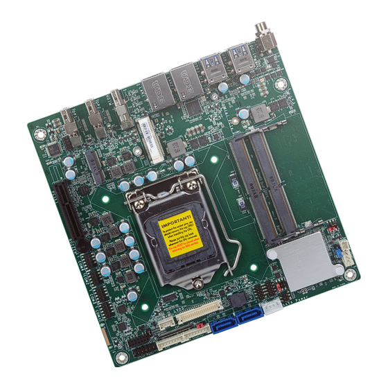
Retention Clip Chapter 2 - Hardware Installation CS101-Q370/C246/H310 www.dfi.com Socket Top View ► System Memory ► Installing the SODIMM Module ► CPU Please follow the steps below to install the memory card into the socket. The system board is equipped with a surface mount LGA 1151 socket. This socket is exclu- sively designed for installing a LGA 1151 packaged Intel CPU. -
Page 11: Installing The Cpu
Chapter 2 - Hardware Installation CS101-Q370/C246/H310 www.dfi.com ► CPU Installing the CPU Load lever 5. Lift the load lever and the load 1. Make sure the PC and all other peripheral devices connected to it have been powered plate all the way up as shown in down. - Page 12 Chapter 2 - Hardware Installation CS101-Q370/C246/H310 www.dfi.com ► CPU ► Installing the CPU Load lever 7-2. Two keys on the sock- 8. Close the load plate Alignment key et and notches on then push the load le- the CPU also facilitate ver down.
-
Page 13: Installing The Fan And Heat Sink
Chapter 2 - Hardware Installation CS101-Q370/C246/H310 www.dfi.com ► CPU Installing the Fan and Heat Sink The CPU must be kept cool by using a CPU fan with heat sink. Without sufficient air circula- 4. Screw tight two of tion across the CPU and heat sink, the CPU will overheat damaging both the CPU and system the spring screws at board. -
Page 14: Jumper Settings
JP7 Pin 1/3/5 is used to select the power level of backlight brightness — +3.3V (default) or +5V. For CS101-Q370/C246 motherboards, JP7 Pin 2/4/6 is also used to select between Mini c) failure to start the system due to BIOS mis-configuration PCIe and mSATA signals. -
Page 15: Lcd/Inverter Power Select
Chapter 2 - Hardware Installation CS101-Q370/C246/H310 www.dfi.com ► Jumper Settings ► Jumper Settings LCD/Inverter Power Select Panel Power Select ▲ 1-2 On: +12V ▲ 1-2 On: +12V (default) ▲ 3-4 On: +5V ▲ 2-3 On: +5V ▲ 5-6 On: +3.3V (default) JP9 is used to select the power level of LVDS LCD inverter connector. -
Page 16: Lvds/Edp Signal Select
Chapter 2 - Hardware Installation CS101-Q370/C246/H310 www.dfi.com ► Jumper Settings LVDS/eDP Signal Select ▲ 1-2 On: eDP JP10 ▲ 2-3 On: LVDS (default) JP10 is used to select the LVDS/eDP signal. -
Page 17: Rear Panel I/O Ports
Two types of DC-in jacks can be selected during procurement — coaxial (default) and 4-pin • 1 DC-in vertical type (optional) as shown below. • 4 USB ports - CS101-Q370/C246: USB 3.1 Gen 2 - CS101-H310: USB 3.1 Gen 1 4-pin Vertical Type (optional) • 2 RJ45 LAN ports DC-in (default) •... -
Page 18: Rj45 Lan Ports
I/O ports. The four USB rear ports support USB 3.1 Gen 1 on CS101-H310, and USB 3.1 Gen 2 on CS101-Q370/C246. Two 10-pin USB internal connectors allow you to connect to 4 The two LAN ports allow the system board to connect to a local area network by means of a additional USB 2.0 ports (USB 5-6/7-8). -
Page 19: Graphics Interfaces
Chapter 2 - Hardware Installation CS101-Q370/C246/H310 www.dfi.com ► Rear Panel I/O Ports Graphics Interfaces The system board contains three display ports — • 1 HDMI port • 2 DP++ ports DP++ 1 HDMI DP++ 2 HDMI Port The HDMI port which carries both digital audio and video signals is used to connect a LCD monitor or digital TV that has the HDMI port. -
Page 20: I/O Connectors
Chapter 2 - Hardware Installation CS101-Q370/C246/H310 www.dfi.com ► I/O Connectors COM (Serial) Ports ▼ COM Port Pin Assignment RS232 RS422 Full Duplex RS485 DCD- TXD- Data- TXD+ Data+ RXD+ N.C. DTR- RXD- N.C. COM 1 DSR- N.C. N.C. COM 3... -
Page 21: Sata (Serial Ata) Connectors
Integrated Advanced Host Controller Interface (AHCI) controller • Supports RAID (for CS101-Q370/C246 only) The Serial ATA connectors are used to connect Serial ATA devices. Connect one end of the Se- rial ATA data cable to a SATA connector and the other end to your Serial ATA device. -
Page 22: Cooling Fan Connector
Chapter 2 - Hardware Installation CS101-Q370/C246/H310 www.dfi.com ► Internal I/O Ports ► Internal I/O Ports Cooling Fan Connector Digital I/O ▲ 4-pin PWM Fan Connector (CPU Fan) 5VSB Digital I/O Power +12V Digital I/O The fan connector is used to power a cooling fan. Cooling fans will provide adequate airflow The 8-bit Digital I/O connector provides powering-on function to external devices that are con- throughout the chassis to prevent overheating the CPU and system board components. -
Page 23: Lvds Lcd Panel
WTB HEADER 40P, 1.25mm, M,H=4.8mm, 180D, SMT, BEIGE, 712-76-40GWE0(PRINEX) RoHS Note: 2. LCD/Inverter Power Connector (DFI PN: 3346-510801-100G) Description: BOX The signal of the LCD panel can only be displayed either via LVDS or via eDP. HEADER 1*8, 8P/2.0mm/180D, 721-81-08TW00(PINREX)RoHS... -
Page 24: Edp Connector (Optional)
Chapter 2 - Hardware Installation CS101-Q370/C246/H310 www.dfi.com ► Internal I/O Ports eDP Connector (optional) ▼ eDP Connector Pin Function Function eDP Panel PWR eDP_Lane 3- eDP_Lane 3+ eDP_Lane 2- eDP_Lane 2+ Hot Plug eDP_GND eDP_Lane 1- eDP_GND eDP_Lane 1+ eDP_GND... -
Page 25: Chassis Intrusion Connector
Chapter 2 - Hardware Installation CS101-Q370/C246/H310 www.dfi.com ► Internal I/O Ports ► Internal I/O Ports Chassis Intrusion Connector Front Panel Connector ▼ Front Panel Connector PWR-LED HD-LED RESET ATX-SW Chassis Intrusion 11 12 Signal ▼ Front Panel Pin Assignment Pin Assignment Pin Assignment N.C. -
Page 26: Expansion Slots
Chapter 2 - Hardware Installation CS101-Q370/C246/H310 www.dfi.com ► Internal I/O Connectors ► Internal I/O Ports ► Expansion Slots Expansion Slots Installing the M.2 Module Before installing the M.2 module into the M.2 socket, please make sure that the following ▼ Top View ▼... -
Page 27: Front Audio Connector
Chapter 2 - Hardware Installation CS101-Q370/C246/H310 www.dfi.com ► Internal I/O Connectors ► Expansion Slots ► Internal I/O Ports Front Audio Connector Please follow the steps below to install the card into the socket. Step 1: Insert the card into the socket... -
Page 28: Lpc Connector
Chapter 2 - Hardware Installation CS101-Q370/C246/H310 www.dfi.com ► Internal I/O Ports ► Internal I/O Ports LPC Connector SMBus Connector ▼ SMBus Connector ▲ LPC Connector The SMBus (System Management Bus) connector is used to connect the SMBus device. It is a The LPC connector is used for debugging and its pin functions are listed below. -
Page 29: Battery
Chapter 2 - Hardware Installation CS101-Q370/C246/H310 www.dfi.com ► Internal I/O Ports Battery Battery Connector +3.3V Connect to the Battery battery connector The lithium ion battery addendum supplies power to the real-time clock and CMOS memory as an auxiliary source of power when the main power is shut off. -
Page 30: Chapter 3 - Bios Setup
Chapter 2 - Hardware Installation CS101-Q370/C246/H310 www.dfi.com Chapter 3 - BIOS Setup ► Overview Legends The BIOS is a program that takes care of the basic level of communication between the CPU and peripherals. It contains codes for various advanced features found in this system board. -
Page 31: Main
Chapter 2 - Hardware Installation CS101-Q370/C246/H310 www.dfi.com ► Main The Main menu is the first screen that you will see when you enter the BIOS Setup Utility. Aptio Setup Utility - Copyright (C) 2019 American Megatrends, Inc. Aptio Setup Utility - Copyright (C) 2019 American Megatrends, Inc. -
Page 32: Advanced
Chapter 2 - Hardware Installation CS101-Q370/C246/H310 www.dfi.com ► Advanced RC ACPI Settings Configure power management related settings in this page. The Advanced menu allows you to configure your system for basic operation. Some entries are defaults required by the system board, while others, if enabled, will improve the performance of your system or let you set some features according to your preference. -
Page 33: Cpu Configuration
Chapter 2 - Hardware Installation CS101-Q370/C246/H310 www.dfi.com ► Advanced ► RC ACPI Settings ► Advanced CPU Configuration Configure CPU processing related settings in this page. Aptio Setup Utility - Copyright (C) 2019 American Megatrends, Inc. Aptio Setup Utility - Copyright (C) 2019 American Megatrends, Inc. -
Page 34: Power & Performance
Chapter 2 - Hardware Installation CS101-Q370/C246/H310 www.dfi.com ► Advanced ► Advanced Power & Performance PCH-FW Configuration Configure the power and performance settings in this page. Configure the parameters of Management Engine Technology. Aptio Setup Utility - Copyright (C) 2019 American Megatrends, Inc. - Page 35 Chapter 2 - Hardware Installation CS101-Q370/C246/H310 www.dfi.com ► Advanced ► PCH-FW Configuration ► Advanced ► PCH-FW Configuration ► AMT Configuration ► AMT Configuration ► Secure Erase Configuration This section is used to configure Secure Erase. Aptio Setup Utility - Copyright (C) 2019 American Megatrends, Inc.
- Page 36 Chapter 2 - Hardware Installation CS101-Q370/C246/H310 www.dfi.com ► Advanced ► PCH-FW Configuration ► Advanced ► PCH-FW Configuration ► AMT Configuration ► OEM Flags Settings ► Firmware Update Configuration Aptio Setup Utility - Copyright (C) 2019 American Megatrends, Inc. Aptio Setup Utility - Copyright (C) 2019 American Megatrends, Inc.
-
Page 37: Trusted Computing
Chapter 2 - Hardware Installation CS101-Q370/C246/H310 www.dfi.com ► Advanced ► Advanced Trusted Computing PTN3460 Configuration Configure Trusted Computing settings. This section configures settings relevant to Trusted Computing innovations. Aptio Setup Utility - Copyright (C) 2019 American Megatrends, Inc. Aptio Setup Utility - Copyright (C) 2019 American Megatrends, Inc. -
Page 38: Nct6116D Super Io Configuration
Chapter 2 - Hardware Installation CS101-Q370/C246/H310 www.dfi.com ► Advanced ► Advanced ► NCT6116D Super IO Configuration NCT6116D Super IO Configuration ► Serial Port 1/2/3/4 Configuration This section is used to configure the I/O functions supported by the onboard Super I/O chip. -
Page 39: Nct6116D Hw Monitor
Chapter 2 - Hardware Installation CS101-Q370/C246/H310 www.dfi.com ► Advanced ► Advanced ► NCT6116D HW Monitor NCT6116D HW Monitor ► Smart Fan Function This section displays the hardware health monitor. Aptio Setup Utility - Copyright (C) 2019 American Megatrends, Inc. Aptio Setup Utility - Copyright (C) 2019 American Megatrends, Inc. -
Page 40: Serial Port Console Redirection
Chapter 2 - Hardware Installation CS101-Q370/C246/H310 www.dfi.com ► Advanced ► NCT6116D HW Monitor ► Advanced Serial Port Console Redirection This section configures settings relevant to serial port console redirection. Aptio Setup Utility - Copyright (C) 2019 American Megatrends, Inc. Aptio Setup Utility - Copyright (C) 2019 American Megatrends, Inc. -
Page 41: Usb Configuration
Chapter 2 - Hardware Installation CS101-Q370/C246/H310 www.dfi.com ► Advanced ► Serial Port Console Redirection ► Advanced USB Configuration ► Console Redirection Settings This section is used to configure the USB settings. Aptio Setup Utility - Copyright (C) 2019 American Megatrends, Inc. -
Page 42: Csm Configuration
Chapter 2 - Hardware Installation CS101-Q370/C246/H310 www.dfi.com ► Advanced ► Advanced CSM Configuration USB Power Control This section is used to configure the CSM settings. Configure USB port power voltage. Aptio Setup Utility - Copyright (C) 2019 American Megatrends, Inc. -
Page 43: Network Stack Configuration
Chapter 2 - Hardware Installation CS101-Q370/C246/H310 www.dfi.com ► Advanced Network Stack Configuration This section is used to configure the Network Stack settings. Aptio Setup Utility - Copyright (C) 2019 American Megatrends, Inc. Advanced Network Stack [Enabled] Enable/Disable UEFI Network Stack... -
Page 44: Chipset
Chapter 2 - Hardware Installation CS101-Q370/C246/H310 www.dfi.com ► Chipset PEG Port Configuration ► Chipset Configure the internal PCIE1 (PCIe x4) channel. This section configures relevant chipset functions. Aptio Setup Utility - Copyright (C) 2019 American Megatrends, Inc. Main Advanced Chipset... -
Page 45: Pch-Io Configuration
Chapter 2 - Hardware Installation CS101-Q370/C246/H310 www.dfi.com ► Chipset ► PEG Port Configuration ► Chipset PCH-IO Configuration ► PEG Port Feature Configuration This section configures the PEG port. Aptio Setup Utility - Copyright (C) 2019 American Megatrends, Inc. Aptio Setup Utility - Copyright (C) 2019 American Megatrends, Inc. - Page 46 Chapter 2 - Hardware Installation CS101-Q370/C246/H310 www.dfi.com ► Chipset ► PCH-IO Configuration ► PCI Express Configuration ► PCI Express Configuration ► LAN2(I211)/M.2-E/M.2-M/Mini PCIe Select a PCIe root port. Aptio Setup Utility - Copyright (C) 2019 American Megatrends, Inc. Aptio Setup Utility - Copyright (C) 2019 American Megatrends, Inc.
- Page 47 Chapter 2 - Hardware Installation CS101-Q370/C246/H310 www.dfi.com ► Chipset ► PCH-IO Configuration ► Chipset ► PCH-IO Configuration ► SATA and RST Configuration ► HD Audio Configuration Aptio Setup Utility - Copyright (C) 2019 American Megatrends, Inc. Aptio Setup Utility - Copyright (C) 2019 American Megatrends, Inc.
-
Page 48: Security
Chapter 2 - Hardware Installation CS101-Q370/C246/H310 www.dfi.com ► Security Aptio Setup Utility - Copyright (C) 2019 American Megatrends, Inc. Aptio Setup Utility - Copyright (C) 2019 American Megatrends, Inc. Main Advanced Chipset Security Boot Save & Exit Security Password Description... -
Page 49: Boot
Chapter 2 - Hardware Installation CS101-Q370/C246/H310 www.dfi.com ► Boot ► Save & Exit Aptio Setup Utility - Copyright (C) 2019 American Megatrends, Inc. Aptio Setup Utility - Copyright (C) 2019 American Megatrends, Inc. Main Advanced Chipset Security Save & Exit... -
Page 50: Updating The Bios
® cal support or your sales representative for the files. You may refer to the how-to video “How to update AMI BIOS in UEFI mode on DFI products?” at https://www.dfi.com/Knowledge/ the safety concerns, the BIOS (SPI ROM) chip cannot be removed from this system board and used on another system board of the same model. -
Page 51: Chapter 4 - Raid
Chapter 4 - RAID ► Settings The system board allows configuring RAID on Serial ATA drives. It supports RAID 0, RAID 1, To enable the RAID function, the steps below are required and elaborated in following sec- RAID 5 and RAID 10. tions. - Page 52 Step 3: Create a RAID Volume Step 4: Install the Intel Rapid Storage Technology Utility 1. Go to the “Advanced” menu of the AMI BIOS and select “Intel(R) Rapid Storage Tech- The Intel Rapid Storage Technology Utility can be installed from within Windows. It allows nology”.
-
Page 53: Chapter 5 - Supported Software
You may also acquire your software from your sales representatives or from the website download page at https://www. dfi.com/DownloadCenter. ► Auto-run Menu After inserting your DVD-ROM into your optical drive, the System Utility auto-run menu may pop up. - Page 54 ► Intel Chipset Software Installation Utility 3. Go through the readme docu- ment for more installation tips then click “Install”. The Intel Chipset Software Installation Utility is used for updating Windows INF files so that ® the Intel chipset can be recognized and configured properly in the system. 1.
- Page 55 ► Intel HD Graphics Drivers 3. Go through the readme docu- ment for system requirements and installation tips then click “Next”. 1. Setup is now ready to in- stall the graphics driver. Click “Next”. 4. Setup is now installing the driver.
- Page 56 ► Realtek Audio Drivers ► Intel LAN Drivers 1. Setup is ready to install the 1. Setup is ready to install the driver. Click “Next”. driver. Click “Next”. 2. Click “Yes, I want to restart my 2. Click “I accept the terms in the computer now”...
- Page 57 ► Intel ME Drivers 4. Click “Install” to begin the in- stallation. 1. Setup is ready to install the driver. Click “Next”. 5. The step displays the installing status in the progress. 2. Read the license agreement then tick “I accept the terms in the License Agreement”.
- Page 58 ► Intel Serial IO Drivers 3. Click “Next” to install to the default folder, or click “Change” to choose another destination folder. 1. Setup is ready to install the driver. Click “Next”. 4. Please wait while the product is being installed. 2.
- Page 59 3. Go through the readme docu- 5. Setup is now installing the ment for system requirements driver. and installation tips then click “Next”. 4. Setup is ready to install the 6. Click “Yes, I want to restart driver. Click “Next”. this computer now”...
- Page 60 ► Adobe Acrobat Reader 9.3 1. Click “Next” to install or click 3. Setup is now installing the “Change Destination Folder” to driver. select another folder. 2. Click “Install” to begin installa- 4. Click “Finish” to exit installa- tion. tion.
- Page 61 ► Intel Rapid Storage Technology 3. Go through the readme document to view system requirements and installation information then click The Intel Rapid Storage Technology is a utility that allows you to monitor the current status “Next”. of the SATA drives. It enables enhanced performance and power management for the storage subsystem.
- Page 62 6. Click “Yes, I want to restart this computer now” to com- plete the installation and then click “Finish”.
-
Page 63: Chapter 6 - Intel Amt Settings
Chapter 6 - Intel AMT Settings Enable Intel AMT in the AMI BIOS ® ► Overview 1. Power-on the system then press <Del> to enter the main menu of the AMI BIOS. Intel Active Management Technology (Intel AMT) combines hardware and software solution to ®... - Page 64 Configure Intel® AMT in the Intel® Management Engine BIOS 4. In the Save & Exit menu, select Save Changes and Reset and then press <Enter>. A dialog box will appear. Select Yes and press Enter to reset the system after saving all Extension (MEBX) changes made.
- Page 65 2. Select MEBx Login and press Enter. You will be prompted for a password. The default 4. You will be asked to verify the new password. Enter the same new password in the space password is “admin”. Enter the default password in the space provided under Intel(R) ME provided under Verify Password then press Enter.
- Page 66 6. If you want to change ME password, select Change ME Password then press Enter. 8. You will be asked to verify the new password. Enter the same new password in the space Enter the current password in the space provided under Intel(R) ME Password then press provided under Verify Password then press Enter.
- Page 67 Press Esc until you return to the Main Menu. Select Intel(R) AMT then press Enter. In the Intel(R) AMT Configuration menu, select Manageability Feature Selection Select Enabled or Disabled then press Enter. then press Enter. Select Enabled or Disabled then press Enter. Intel(R) Management Engine BIOS Extension v12.0.0.0010/Intel(R) ME v12.0.40.1433 Intel(R) Management Engine BIOS Extension v12.0.0.0010/Intel(R) ME v12.0.40.1433 Copyright(C) 2003-17 Intel Corporation.
- Page 68 Select SOL then press Enter. Select Enabled or Disabled then press Enter. Select KVM Feature Selection then press Enter. Select Enabled or Disabled then press Enter. Intel(R) Management Engine BIOS Extension v12.0.0.0010/Intel(R) ME v12.0.40.1433 Intel(R) Management Engine BIOS Extension v12.0.0.0010/Intel(R) ME v12.0.40.1433 Copyright(C) 2003-17 Intel Corporation.
- Page 69 In the User Consent menu, select User Opt-in then press Enter. Select NONE or KVM Press Esc until you return to the Intel(R) AMT Configuration menu. Select Password or ALL then press Enter. Policy then press Enter. You may choose to use a password only during setup and configuration or to use a pass- word anytime the system is being accessed.
- Page 70 In the Intel(R) ME Network Setup menu, select Intel(R) ME Network Name Set- Select Domain Name then press Enter. Enter the computer’s domain name then press tings then press Enter. Enter. Intel(R) Management Engine BIOS Extension v12.0.0.0010/Intel(R) ME v12.0.40.1433 Intel(R) Management Engine BIOS Extension v12.0.0.0010/Intel(R) ME v12.0.40.1433 Copyright(C) 2003-17 Intel Corporation.
- Page 71 Select TTL then press Enter. Enter value then press Enter. Select Dynamic DNS Update then press Enter. Select Enabled or Disabled then press Enter. If Dynamic DNS Update is set to Enabled, Periodic Update Interval and TTL fields will show up. Intel(R) Management Engine BIOS Extension v12.0.0.0010/Intel(R) ME v12.0.40.1433 Intel(R) Management Engine BIOS Extension v12.0.0.0010/Intel(R) ME v12.0.40.1433 Copyright(C) 2003-17 Intel Corporation.
- Page 72 In the Wired LAN IPV4 Configuration menu, select DHCP Mode then press Enter. Select Subnet Mask Address then press Enter. Enter address then press Enter. Select Enabled or Disabled then press Enter. If set to Disabled, IPV4 Address, Subnet Mask Address, Default Gateway Address, Preferred DNS Address and Alternate DNS Address will show up.
- Page 73 Select Preferred DNS Address then press Enter. Enter address then press Enter. Press Esc until you return to the Intel(R) AMT Configuration menu. If you want to activate the current network settings and open the ME network inferface, select Activate Network Access, press Enter, then press Y.
- Page 74 In the Intel(R) AMT Configuration menu, select Remote Setup And Configuration In the Intel(R) Remote Setup And Configuration menu, select Provisioning Re- then press Enter. cord then press Enter. Intel(R) Management Engine BIOS Extension v12.0.0.0010/Intel(R) ME v12.0.40.1433 Intel(R) Management Engine BIOS Extension v12.0.0.0010/Intel(R) ME v12.0.40.1433 Copyright(C) 2003-17 Intel Corporation.
- Page 75 In the Intel(R) Remote Setup And Configuration menu, select Provisioning Press Esc until you return to the Intel(R) Remote Setup And Configuration menu. Server FQDN then press Enter. Enter the FQDN then press Enter. Select TLS PKI then press Enter. Select Remote Configuration ** then press Enter. Select Enabled or Disabled then press Enter.
- Page 76 In the Intel(R) Remote Configuration menu, select Manage Hashes then press In the Intel(R) AMT Power Control menu, select Idle Timeout then press Enter. Enter. Select the hash name then press Insert to enter custom hash certificate name, Enter the timeout value and press Enter. press Delete to delete hash, press Enter to view hash information, press + to activate or deactivate hash, and press Esc to exit.
Need help?
Do you have a question about the CS101-Q370 and is the answer not in the manual?
Questions and answers