
Subscribe to Our Youtube Channel
Related Manuals for Maxon MicroMaster LT


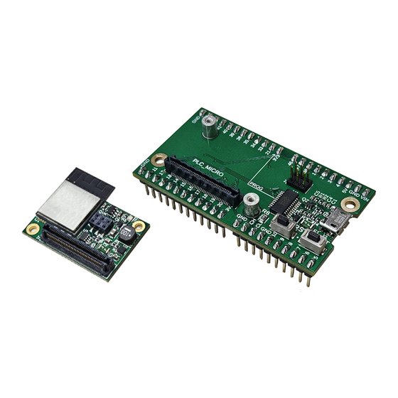
Summary of Contents for Maxon MicroMaster LT
- Page 1 MicroMaster LT CANopen Master Controller MicroBreakout Evaluation Board Hardware Reference MicroMaster LT Hardware Reference MMAU | Edition 2024-01...
-
Page 2: Table Of Contents
• you must follow the instructions given therein. The MicroMaster LT and MicroBreakout Evaluation Board are considered as partly completed machinery according to EU Directive 2006/42/EC, Article 2, Clause (g) and is intended to be incorporated into or assembled with other machinery or other partly completed machinery or equipment. - Page 3 ........LIST OF FIGURES LIST OF TABLES MicroMaster LT Hardware Reference MMAU | 2024-01...
-
Page 4: About
1.1.1 Intended Purpose docu- The purpose of the present document is to familiarize you with the MicroMaster LT CANopen Master Controller ment to... and its corresponding evaluation board. It will highlight the tasks for safe and adequate installation and/or –stay safe, commissioning. - Page 5 About About this Document Meaning Notation CANopen® © CiA CAN in Automation e.V, DE-Nuremberg CiA® Table 1-2 Brand names and trademark owners MicroMaster LT Hardware Reference MMAU | 2024-01...
- Page 6 The MicroBreakout Evaluation Board is a programming evaluation board that was developed to complement the MicroMaster LT. This evaluation board offers the ability to directly program the module from a programming environment. The board offers the MicroMaster LT general-purpose IOs on pin headers for rapid prototyping and testing.
-
Page 7: Specifications
Dimensions (L x W x H) Breakout 60.0 x 32.0 x 15.1 mm MicroMaster Mounting holes for 2 x M2 screws, must be PCB mounted Mounting Breakout Mounting holes for 2 x M2.5 screws Table 2-4 Technical Data MicroMaster LT Hardware Reference MMAU | 2024-01... -
Page 8: Dimensional Drawing
Specifications Dimensional drawing Dimensional drawing Figure 2-1 Micro (External Antenna) - Dimensional drawing [mm] Figure 2-2 Micro (Internal Antenna) - Dimensional drawing [mm] MicroMaster LT Hardware Reference MMAU | 2024-01... -
Page 9: Figure 2-3 Breakout Board - Dimensional Drawing [Mm]
Specifications Dimensional drawing Figure 2-3 Breakout Board - Dimensional drawing [mm] MicroMaster LT Hardware Reference MMAU | 2024-01... -
Page 10: Figure 2-4 Breakout Board - Footprint
Specifications Dimensional drawing 27.94 Figure 2-4 Breakout Board - Footprint MicroMaster LT Hardware Reference MMAU | 2024-01 2-10... -
Page 11: Generally Applicable Rules
The USB cable should be connected to the USB interface of the breakout board first before being connected to the PC/Notebook. DO NOT connect the USB interface while externally powering the device from the +5V pin. This can damage the MicroMaster LT, the breakout board, or the PC/Notebook. MicroMaster LT Hardware Reference MMAU | 2024-01... -
Page 12: Connections - Micromaster Lt
Connections - MicroMaster LT Antenna Connector (Ext. Ant. Programming Version Only) Receptacle Figure 3-5 MicroMaster LT - Connection Locations Signal Chip_PU (RESET) U0TXD (Programming UART interface transmit) GPIO 0 (BOOT) U0RXD (Programming UART interface receive) GPIO 45 GPIO 46 GPIO 15 GPIO 16 A9...A10... - Page 13 Setup Connections - MicroMaster LT Signal GPIO 17 GPIO 18 GPIO 19 GPIO 20 GPIO 21 A47...A48 not connected GPIO 34 GPIO 47 GPIO 33 GPIO 48 A53...A54 not connected GPIO 2 GPIO 1 A57...A58 Ground A59...A62 not connected A63...A64...
-
Page 14: Connections - Breakout
Pin A-1 Pin B-1 CANopen Master Receptacle Pin A-12 Pin B-12 Pin A-13 Pin B-13 Programming RESET Header BOOT USB Port Pin A-22 Pin B-22 Figure 3-6 Breakout Board - Connection Locations MicroMaster LT Hardware Reference MMAU | 2024-01 3-14... -
Page 15: Pin Assignment
The CAN bus of the Breakout Board has an integrated 120 Ω termination resistor. This resistor is fixed, so the board must be placed at an end of the connected CAN bus. MicroMaster LT Hardware Reference MMAU | 2024-01 3-15... -
Page 16: Connection Functions
A USB Type A - micro B Cable is required to connect to the USB interface for programming or monitoring. The USB interface provides power to the MicroMaster LT while plugged in. A USB port can also be added externally using GPIO 19 and 20’s USB D- and D+ functionality. This port can be used either for a USB 2.0 OTG interface or as a secondary programming/monitoring interface. -
Page 17: Buttons
The two push buttons on the Breakout, BOOT and RESET, are to be used when programming and monitoring the device. The RESET button behaves similarly to a power cycle event of the MicroMaster LT controller. If the RESET button is triggered, the loaded program will be restarted. -
Page 18: Programming Interface
An optional programming board can be used, which can be used to upload programs to a MicroMaster that is installed on a motherboard without its own USB-serial programming interface. Figure 3-9 The standalone programmer can be used to program a MicroMaster that is in-situ. MicroMaster LT Hardware Reference MMAU | 2024-01 3-18... -
Page 19: Recommended Components And Manufacturers
If you are not trained in the design and development of printed circuit boards, you will need additional sup- maxon will be happy to provide you with a quote for designing and manufacturing a motherboard for your port for this point. -
Page 20: Design Guidelines
CAN Bus The CAN bus of the MicroMaster LT does not have an integrated 120 Ω termination resistor. As the MicroMaster LT must be used in a motherboard, the termination resistor should be placed on the motherboard if required. MicroMaster LT Hardware Reference... -
Page 21: Terminal/Socket Placement & Footprint
Terminal/Socket Placement & SMT Footprint Open pin side Spacer (Ø4.3x5 mm, M2) Figure 4-10 MicroMaster LT - Terminal/socket placement (example) Figure 4-46 EPOS4 Micro 24/5 CAN – Terminal/socket placement (example) Mirroring of terminal rows The socket is of a hermaphroditic design. When mating the Module’s socket onto the motherboard’s socket, Mirroring of terminal rows �... -
Page 22: Figure 4-12 Micromaster Lt - Terminal & Spacer Footprint
STEP file. Use only the below stated dimensions for your design. Figure 4-48 EPOS4 Micro 24/5 CAN– Terminal/socket footprint Figure 4-12 MicroMaster LT - Terminal & spacer footprint EPOS4 Micro 24/5 CAN Hardware Reference 4-74 CCMC | 2022-04 | rel10496... -
Page 23: Figure 5-13 Main Wiring Diagram
GPIO 46 GPIO 47 GPIO 10 GPIO 48 GPIO 9 GPIO 1 GPIO 8 GPIO 2 GPIO 7 GPIO 3 GPIO 6 GPIO 4 GPIO 5 200 nF Figure 5-13 Main wiring diagram MicroMaster LT Hardware Reference MMAU | 2024-01 5-23... - Page 24 MicroMaster LT - Terminal & spacer footprint ....... . .
- Page 25 Table 4-8 Motherboard Design Guide - Recommended components ......MicroMaster LT Hardware Reference MMAU | 2024-01...
Need help?
Do you have a question about the MicroMaster LT and is the answer not in the manual?
Questions and answers