
Related Manuals for Maxon ESCON Module 50/8


Summary of Contents for Maxon ESCON Module 50/8
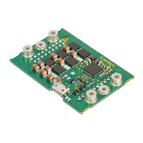
- Page 1 Hardware Reference ESCON Module 50/8 Servo Controller | P/N not defined Hardware Reference CCMC | Edition 2021-08 | DocID rel10243...
-
Page 2: Table Of Contents
• you must follow the instructions given therein. The ESCON Module 50/8 is considered as partly completed machinery according to EU Directive 2006/42/EC, Article 2, Clause (g) and is intended to be incorporated into or assembled with other machinery or other partly completed machinery or equipment. - Page 3 Dimensional Drawing..........42 ESCON Module 50/8 Motherboard (586048) ......42 Spare Parts .
- Page 4 • • p a g e i n t e n t i o n a l l y l e f t b l a n k • • ESCON Module 50/8 Hardware Reference CCMC | 2021-08 | rel10243...
-
Page 5: About
About this Document 1.1.1 Intended Purpose The purpose of the present document is to familiarize you with the ESCON Module 50/8 Servo Controller. It will highlight the tasks for safe and adequate installation and/or commissioning. Follow the described instructions …... -
Page 6: Table 1-2 Symbols & Signs
Brand Name Trademark Owner Certonal® © Acota Limited, GB-Shrewsbury Littelfuse® © Littelfuse, USA-Chicago, IL SMD NANO2® Windows® © Microsoft Corporation, USA-Redmond, WA Table 1-3 Brand Names and Trademark Owners ESCON Module 50/8 Hardware Reference CCMC | 2021-08 | rel10243... -
Page 7: About The Device
Certonal FC-742 protective coating. The servo controller is available in two variants – as «ESCON Module 50/8 HE» (586137) with heat sink and as «ESCON Module 50/8» (532872) without heat sink. Latter is designed for the use with a suitable, individually selectable heat sink. -
Page 8: About The Safety Precautions
– and be kept – in a safe operating mode. • Be aware that you are not entitled to perform any repair on components supplied by maxon. Electrostatic Sensitive Device (ESD) •... -
Page 9: Specifications
Specifications Technical Data SPECIFICATIONS Technical Data ESCON Module 50/8 (532872) ESCON Module 50/8 HE (586137) Nominal operating voltage +V 10…50 VDC Absolute operating voltage 8 VDC/56 VDC CC min CC max 0.98 x +V Output voltage (max.) Output current I (<20 s) - Page 10 5…90% (condensation not permitted) Operation within the extended range (temperature and altitude) is permitted. For this purpose, however, the adjustment of ambient temperature and power dissipation (and for the ESCON Module 50/8 also a possibly necessary heat sink) must be observed.
-
Page 11: Thermal Data
If you are using an ESCON Module 50/8 and want to fully utilize the extended temperature, you will need to provide a suitable heat sink. From the following graphs you can see the maximum heat resistance R... -
Page 12: Limitations
°C (Y-axis) a heat sink with a maximum heat resistance R of less than 4 K/W is required (yellow characteristic). Use the maxon accessory «ESCON Module 50/8 Thermal Pad» (586142) for optimum heat transfer and observe the manufacturer's specifications for the respective heat sink. Specification / Accessories Dimensions 53.3 x 37.5 x 16.5 mm (L x B x H) -
Page 13: Dimensional Drawings
Specifications Dimensional Drawings Dimensional Drawings Figure 2-3 ESCON Module 50/8 – Dimensional Drawing [mm] Figure 2-4 ESCON Module 50/8 HE – Dimensional Drawing [mm] ESCON Module 50/8 Hardware Reference 2-13 CCMC | 2021-08 | rel10243... -
Page 14: Standards
Component stress: In accordance with circuit diagram and Reliability MIL-HDBK-217F nominal power Mean Time Between Failures (MTBF) • ESCON Module 50/8: 380'195 hours • ESCON Module 50/8 HE: 517'288 hours Table 2-7 Standards ESCON Module 50/8 Hardware Reference 2-14 CCMC | 2021-08 | rel10243... -
Page 15: Setup
• Note that the necessary output current is depending on the load torque. Yet, the output current limits of the ESCON Module 50/8 are as follows; continuous max. 8 A / short-time (acceleration) max. 15 A. Hot plugging the USB Interface may cause Hardware Damage If the USB interface is being hot-plugged (connecting while the power supply is on), the possibly high differ- ences in potential of the two power supplies of controller and PC/Notebook can lead to damaged hardware. -
Page 16: Configuration Of Power Supply
SOUGHT VALUE: • Supply voltage +V [Volt] SOLUTION: Δn ≥ ⋅ ⋅ ⋅ 1 V [ ] ------ - -------- - M --------- - ΔM 0.98 ESCON Module 50/8 Hardware Reference 3-16 CCMC | 2021-08 | rel10243... -
Page 17: Connections
Hall sensor 2 Hall sensor 2 input Channel B Encoder channel B Hall sensor 3 Hall sensor 3 input Channel B\ Encoder channel B complement Table 3-8 Pin Assignment (Pins 1-18) ESCON Module 50/8 Hardware Reference 3-17 CCMC | 2021-08 | rel10243... -
Page 18: Figure 3-5 Pin Assignment
Analog input 2, negative signal AnIN2+ Analog input 2, positive signal AnIN1− Analog input 1, negative signal AnIN1+ Analog input 1, positive signal Table 3-9 Pin Assignment (Pins 19-29) ESCON Module 50/8 Hardware Reference 3-18 CCMC | 2021-08 | rel10243... -
Page 19: Figure 3-7 Hall Sensor 1 Input Circuit (Analogously Valid Also For Hall Sensors 2 & 3)
Logic 1 typically >2.4 V Internal pull-up resistor 10 kΩ (referenced to +5.45 V) Figure 3-7 Hall Sensor 1 Input Circuit (analogously valid also for Hall Sensors 2 & 3) ESCON Module 50/8 Hardware Reference 3-19 CCMC | 2021-08 | rel10243... -
Page 20: Figure 3-8 Encoder Input Circuit Ch A "Differential" (Analogously Valid Also For Ch B)
Max. input voltage +12 VDC/−12 VDC Line receiver (internal) EIA RS422 standard Max. input frequency 1 MHz Figure 3-8 Encoder Input Circuit Ch A “Differential” (analogously valid also for Ch B) ESCON Module 50/8 Hardware Reference 3-20 CCMC | 2021-08 | rel10243... -
Page 21: Figure 3-9 Encoder Input Circuit Ch A "Single-Ended" (Analogously Valid Also For Ch B)
= typically −170 μA @ 0 V Input low current Max. input frequency 100 kHz Figure 3-9 Encoder Input Circuit Ch A “Single-ended” (analogously valid also for Ch B) ESCON Module 50/8 Hardware Reference 3-21 CCMC | 2021-08 | rel10243... -
Page 22: Figure 3-10 Digin1 Circuit
0.1% @ 10 Hz PWM accuracy typically 0.5% @ 1 kHz typically 2.5% @ 5 kHz RC Servo cycle duration 3…30 ms RC Servo pulse length 1…2 ms Figure 3-10 DigIN1 Circuit ESCON Module 50/8 Hardware Reference 3-22 CCMC | 2021-08 | rel10243... -
Page 23: Figure 3-11 Digin2 Circuit
38.5 kΩ (@ 5 V) typically 25.5 kΩ (@ 24 V) Input current at logic 1 typically 130 µA @ +5 VDC Switching delay <8 ms Figure 3-11 DigIN2 Circuit ESCON Module 50/8 Hardware Reference 3-23 CCMC | 2021-08 | rel10243... -
Page 24: Figure 3-12 Digin3 Circuit (Analogously Valid Also For Digin4)
25.5 kΩ (@ 24 V) Input current at logic 1 typically 130 µA @ +5 VDC Switching delay <8 ms Figure 3-12 DigIN3 Circuit (analogously valid also for DigIN4) ESCON Module 50/8 Hardware Reference 3-24 CCMC | 2021-08 | rel10243... -
Page 25: Figure 3-13 Digout3 Circuit (Analogously Valid Also For Digout4)
Max. load inductance 100 mH @ 24 VDC; 500 mA Figure 3-13 DigOUT3 Circuit (analogously valid also for DigOUT4) Figure 3-14 DigOUT3 Wiring Examples (analogously valid also for DigOUT4) ESCON Module 50/8 Hardware Reference 3-25 CCMC | 2021-08 | rel10243... -
Page 26: Figure 3-15 Anin1 Circuit (Analogously Valid Also For Anin2)
Note: The rate of the increase is limited in Max. capacitive load proportion to the capacitive load (e.g. 5 V/ms @300 nF). Max. output current limit 1 mA Figure 3-16 AnOUT1 Circuit (analogously valid also for AnOUT2) ESCON Module 50/8 Hardware Reference 3-26 CCMC | 2021-08 | rel10243... -
Page 27: Figure 3-17 Usb Socket J7
According to USB 2.0 / USB 3.0 specification Length 1.5 m Head A USB type “micro B”, male Head B USB type “A”, male Table 3-11 USB Type A - micro B Cable ESCON Module 50/8 Hardware Reference 3-27 CCMC | 2021-08 | rel10243... -
Page 28: Status Indicators
• DC Tacho Polarity Error ERROR • PWM Set Value Input out of Range Error • Hall Sensor Pattern Error ERROR • Hall Sensor Sequence Error • Hall Sensor Frequency too high Error ESCON Module 50/8 Hardware Reference 3-28 CCMC | 2021-08 | rel10243... -
Page 29: Table 3-12 Leds - Interpretation Of Condition
Setup Status Indicators Status/Error Green • Auto Tuning Identification Error ERROR • Internal Software Error Table 3-12 LEDs – Interpretation of Condition ESCON Module 50/8 Hardware Reference 3-29 CCMC | 2021-08 | rel10243... - Page 30 Status Indicators • • p a g e i n t e n t i o n a l l y l e f t b l a n k • • ESCON Module 50/8 Hardware Reference 3-30 CCMC | 2021-08 | rel10243...
-
Page 31: Wiring
Wiring WIRING Figure 4-19 Interfaces – Designations and Location Note The subsequent diagrams feature this symbol: • Ground safety earth connection (optional) ESCON Module 50/8 Hardware Reference 4-31 CCMC | 2021-08 | rel10243... -
Page 32: Dc Motors
Wiring DC Motors DC Motors MAXON DC MOTOR Figure 4-20 maxon DC motor ESCON Module 50/8 Hardware Reference 4-32 CCMC | 2021-08 | rel10243... -
Page 33: Figure 4-21 Maxon Dc Motor With Dc Tacho
Wiring DC Motors MAXON DC MOTOR WITH DC TACHO Figure 4-21 maxon DC motor with DC Tacho ESCON Module 50/8 Hardware Reference 4-33 CCMC | 2021-08 | rel10243... -
Page 34: Figure 4-22 Maxon Dc Motor With Encoder
Wiring DC Motors MAXON DC MOTOR WITH ENCODER Figure 4-22 maxon DC motor with Encoder ESCON Module 50/8 Hardware Reference 4-34 CCMC | 2021-08 | rel10243... -
Page 35: Ec Motors
Wiring EC Motors EC Motors MAXON EC MOTOR WITH HALL SENSORS Figure 4-23 maxon EC motor with Hall Sensors ESCON Module 50/8 Hardware Reference 4-35 CCMC | 2021-08 | rel10243... -
Page 36: Figure 4-24 Maxon Ec Motor With Hall Sensors & Encoder
Wiring EC Motors MAXON EC MOTOR WITH HALL SENSORS & ENCODER Figure 4-24 maxon EC motor with Hall Sensors & Encoder ESCON Module 50/8 Hardware Reference 4-36 CCMC | 2021-08 | rel10243... -
Page 37: Motherboard Design Guide
5.1.2 Supply Voltage To protect the ESCON Module 50/8, we recommend using an external circuit breaker, a TVS diode, and a capacitor in the voltage supply cable. In this regard, please note the following recommendations: Figure 5-25 Wiring of Voltage Supply Cable INPUT FUSE (FU1) An input fuse (FU1) is necessary in order to provide reverse polarity protection. - Page 38 TVS (transient voltage suppressor) diode (D1) to the voltage supply cable. CAPACITOR (C1) The function of the ESCON Module 50/8 does not necessarily require the use of an external capacitor (C1). To further reduce voltage ripple and feedback currents, an electrolytic capacitor can be connected to the voltage supply cable.
-
Page 39: Figure 5-26 Wiring Of Motor Winding 1 (Analogously Valid Also For Motor Windings 2 & 3)
The below wiring examples refer to addi- tional inductances of 4.7 μH and 22 μH. If a different additional inductance is required, also the filter compo- nents must be adapted accordingly. Should you need further help with the filter design, contact maxon Sup- port at http://support.maxongroup.com. -
Page 40: Design Guidelines
Motherboard Design Guide – Recommended Components Design Guidelines The following instructions are intended to serve as an aid for designing an application-specific motherboard and ensuring the correct and reliable integration of the ESCON Module 50/8. ESCON Module 50/8 Hardware Reference 5-40... -
Page 41: Tht Footprint
5.2.1 Ground All ground connections (GND) should be internally connected to the ESCON Module 50/8 (equal potential). It is customary to equip the motherboard with a ground plane. All ground connections should be connected to the voltage supply ground via wide conductive tracks. -
Page 42: Dimensional Drawing
ESCON Module 50/8 Motherboard (586048) As an alternative to the development of a motherboard the «ESCON Module 50/8 Motherboard» (subse- quently named ESCON Module 50/8 MoBo) is available. All required connections are already in place and designed as screw-type terminals. -
Page 43: Figure 5-30 Escon Module 50/8 Mobo - Mounting On Din Rail
ESCON Module 50/8 Motherboard (586048) 5.7.1 Assembly The ESCON Module 50/8 MoBo is designed to easily be screw-mounted or integrated into standard rail sys- tems. For ordering information for the components required Figure 5-30 (only for illustrative purposes) and Table 5-15. -
Page 44: Figure 5-31 Escon Module 50/8 Mobo - Power Plug J1
Pluggable screw-type terminal block, 2 poles, 3.5 mm pitch 0.14…1.5 mm multi-core, AWG 28-14 Suitable cables 0.14…1.5 mm single wire, AWG 28-14 Table 5-17 ESCON Module 50/8 MoBo – Power Plug J1 – Specification & Accessories ESCON Module 50/8 Hardware Reference 5-44 CCMC | 2021-08 | rel10243... -
Page 45: Figure 5-32 Escon Module 50/8 Mobo - Motor Plug J2
Motherboard Design Guide ESCON Module 50/8 Motherboard (586048) 5.7.2.2 Motor (J2) The servo controller is set to drive either maxon DC motors (brushed) or maxon EC motors (brushless). Figure 5-32 ESCON Module 50/8 MoBo – Motor Plug J2 Signal Description... -
Page 46: Figure 5-33 Escon Module 50/8 Mobo - Hall Sensor Plug J3
Pluggable screw-type terminal block, 5 poles, 3.5 mm pitch 0.14…1.5 mm multi-core, AWG 28-14 Suitable cables 0.14…1.5 mm single wire, AWG 28-14 Table 5-22 ESCON Module 50/8 MoBo – Hall Sensor Plug J3 – Specification & Accessories ESCON Module 50/8 Hardware Reference 5-46 CCMC | 2021-08 | rel10243... -
Page 47: Figure 5-34 Escon Module 50/8 Mobo - Encoder Socket J4
Channel B not connected – not connected – Table 5-23 ESCON Module 50/8 MoBo – Encoder Socket J4 – Pin Assignment Accessories For sockets with strain relief: 1 retainer clip, height 13.5 mm, 3M (3505-8110) Retainer Suitable strain For sockets without strain relief: relief 1 retainer clip, height 7.9 mm, 3M (3505-8010) -
Page 48: Table 5-25 Escon Module 50/8 Mobo - Encoder Cable
Head B DIN 41651 connector, 2.54 mm pitch, 10 poles, with strain relief Table 5-25 ESCON Module 50/8 MoBo – Encoder Cable Best practice • Because of its resistance against electrical interferences, we recommend using differential scheme. Nevertheless, the controller supports both schemes – differential and single-ended. -
Page 49: Figure 5-35 Escon Module 50/8 Mobo - Digital I/Os Plug J5
Pluggable screw-type terminal block, 6 poles, 3.5 mm pitch 0.14…1.5 mm multi-core, AWG 28-14 Suitable cables 0.14…1.5 mm single wire, AWG 28-14 Table 5-27 ESCON Module 50/8 MoBo – Digital I/Os Plug J5 – Specification & Accessories ESCON Module 50/8 Hardware Reference 5-49 CCMC | 2021-08 | rel10243... -
Page 50: Figure 5-36 Escon Module 50/8 Mobo - Analog I/Os Plug J6
Pluggable screw-type terminal block, 7 poles, 3.5 mm pitch 0.14…1.5 mm multi-core, AWG 28-14 Suitable cables 0.14…1.5 mm single wire, AWG 28-14 Table 5-29 ESCON Module 50/8 MoBo – Analog I/Os Plug J6 – Specification & Accessories ESCON Module 50/8 Hardware Reference 5-50 CCMC | 2021-08 | rel10243... -
Page 51: Figure 5-37 Escon Module 50/8 Mobo - Maxon Dc Motor (J2)
Motherboard Design Guide ESCON Module 50/8 Motherboard (586048) 5.7.3 Wiring Note The USB interface is located directly at the ESCON Module 50/8. Note The subsequent diagrams feature this symbol: • Ground safety earth connection (optional) 5.7.3.1 DC Motors MAXON DC MOTOR Figure 5-37 ESCON Module 50/8 MoBo –... -
Page 52: Figure 5-38 Escon Module 50/8 Mobo - Maxon Dc Motor With Dc Tacho (J2)
Motherboard Design Guide ESCON Module 50/8 Motherboard (586048) MAXON DC MOTOR WITH DC TACHO Figure 5-38 ESCON Module 50/8 MoBo – maxon DC motor with DC Tacho (J2) ESCON Module 50/8 Hardware Reference 5-52 CCMC | 2021-08 | rel10243... -
Page 53: Figure 5-39 Escon Module 50/8 Mobo - Maxon Dc Motor With Encoder (J2 / J4)
Motherboard Design Guide ESCON Module 50/8 Motherboard (586048) MAXON DC MOTOR WITH ENCODER Figure 5-39 ESCON Module 50/8 MoBo – maxon DC motor with Encoder (J2 / J4) ESCON Module 50/8 Hardware Reference 5-53 CCMC | 2021-08 | rel10243... -
Page 54: Figure 5-40 Escon Module 50/8 Mobo - Maxon Ec Motor With Hall Sensors (J2 / J3)
ESCON Module 50/8 Motherboard (586048) 5.7.3.2 EC motors MAXON EC MOTOR WITH HALL SENSORS Figure 5-40 ESCON Module 50/8 MoBo – maxon EC motor with Hall Sensors (J2 / J3) ESCON Module 50/8 Hardware Reference 5-54 CCMC | 2021-08 | rel10243... -
Page 55: Figure 5-41 Escon Module 50/8 Mobo - Maxon Ec Motor With Hall Sensors & Encoders (J2 / J3 / J4)
ESCON Module 50/8 Motherboard (586048) MAXON EC MOTOR WITH HALL SENSORS & ENCODER Figure 5-41 ESCON Module 50/8 MoBo – maxon EC motor with Hall Sensors & Encoders (J2 / J3 / J4) ESCON Module 50/8 Hardware Reference 5-55 CCMC | 2021-08 | rel10243... -
Page 56: Spare Parts
5-pole pluggable screw-type terminal block, 3.5 mm pitch, labeled 1…5 444147 6-pole pluggable screw-type terminal block, 3.5 mm pitch, labeled 1…6 444148 7-pole pluggable screw-type terminal block, 3.5 mm pitch, labeled 1…7 Table 5-30 Spare Parts List ESCON Module 50/8 Hardware Reference 5-56 CCMC | 2021-08 | rel10243... -
Page 57: List Of Figures
ESCON Module 50/8 MoBo – maxon EC motor with Hall Sensors (J2 / J3)......54... -
Page 58: List Of Tables
Table 5-20 ESCON Module 50/8 MoBo – Motor Plug J2 – Specification & Accessories ......45 Table 5-21 ESCON Module 50/8 MoBo –... -
Page 59: Index
586137 9 586141 12 digital inputs 22 586142 12 error display 28 performance data 9 ESCON Module 50/8 Heat Sink 12 pin assignment 17 ESCON Module 50/8 Thermal Pad 12 precautions 8 ESD 8 prerequisites prior installation 15 EU directive, applicable 15... - Page 60 Index technical data 9 thermal pad, see «ESCON Module 50/8 Thermal Pad» USB interface 27 wiring diagrams for DC motors 32 EC motors 35 ESCON Module 50/8 Hardware Reference Z-60 CCMC | 2021-08 | rel10243...
- Page 61 Index • • p a g e i n t e n t i o n a l l y l e f t b l a n k • • ESCON Module 50/8 Hardware Reference Z-61 CCMC | 2021-08 | rel10243...
- Page 62 © 2021 maxon. All rights reserved. Subject to change without prior notice.
Need help?
Do you have a question about the ESCON Module 50/8 and is the answer not in the manual?
Questions and answers