
Subscribe to Our Youtube Channel
Related Manuals for Maxon EP0S4 Disk 60/12


Summary of Contents for Maxon EP0S4 Disk 60/12
- Page 1 Hardware Reference EPOS4 Disk 60/12 Positioning Controller | P/Ns 688775 / 709859 / 688777 / 709862 Hardware Reference CCMC | Edition 2023-07 | DocID rel11751...
-
Page 2: Table Of Contents
Table of Contents TABLE OF CONTENTS ABOUT About this Document..........5 About the Device. - Page 3 Table of Contents 3.3.13 Brake (X16) ............. 48 Prefab Cable Assemblies .
- Page 4 Table of Contents • • p a g e i n t e n t i o n a l l y l e f t b l a n k • • EPOS4 Disk 60/12 Hardware Reference CCMC | 2023-07 | rel11751...
-
Page 5: About
About About this Document ABOUT About this Document 1.1.1 Intended Purpose docu- The purpose of the present document is to familiarize you with the EPOS4 Disk 60/12 positioning controller. It will highlight the tasks for safe and adequate installation and/or commissioning. Follow the described ment to…... - Page 6 About About this Document 1.1.3 How to use Throughout the document, the following notations and codes will be used. Notation Meaning refers to an item (such as part numbers, list items, etc.) denotes “see”, “see also”, “take note of” or “go to” ...
- Page 7 1.1.6 Copyright © 2023 maxon. All rights reserved. Any use, in particular reproduction, editing, translation, and copying, without prior written approval is not permitted (contact: maxon international ltd., Brünigstrasse 220, CH- 6072 Sachseln, +41 41 666 15 00, www.maxongroup.com). Infringements will be prosecuted under civil and criminal law.
-
Page 8: About The Device
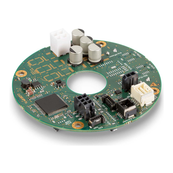
About the Device About the Device maxon’s EPOS4 Disk 60/12 is a round-sized, full digital, smart positioning control unit with a center hole for Capabilities of the cable feed-trough. Its high power density allows flexible use for brushed DC and brushless EC (BLDC) -
Page 9: About The Safety Precautions
– and be kept – in a safe operating mode. • Be aware that you are not entitled to perform any repair on components supplied by maxon. Electrostatic sensitive device (ESD) •... - Page 10 About About the Safety Precautions • • p a g e i n t e n t i o n a l l y l e f t b l a n k • • EPOS4 Disk 60/12 Hardware Reference 1-10 CCMC | 2023-07 | rel11751...
-
Page 11: Specifications
Specifications Technical Data SPECIFICATIONS Technical Data EPOS4 Disk 60/12 CAN (688775) EPOS4 Disk 60/12 EtherCAT (688777) EPOS4 Disk 60/12 CAN SSC (709859) EPOS4 Disk 60/12 EtherCAT SSC (709862) Nominal power supply voltage +V 12…60 VDC Nominal logic supply voltage +V 12…60 VDC Absolute supply voltage +V / +V... - Page 12 Specifications Technical Data EPOS4 Disk 60/12 CAN (688775) EPOS4 Disk 60/12 EtherCAT (688777) EPOS4 Disk 60/12 CAN SSC (709859) EPOS4 Disk 60/12 EtherCAT SSC (709862) Sensor signals (choice between multiple Inputs functions) & • SSI absolute encoder signals EIA RS422, 0.4…2 MHz, configurable Outputs •...
-
Page 13: Thermal Data
Specifications Thermal Data Thermal Data 2.2.1 Derating of Output Current Mandatory operation within the specified limits Operation within the stated derating specifications is mandatory. Exceeding ambient temperatures beyond the specified limits can lead to thermal overload even at low output currents. Disk CAN Disk EtherCAT Figure 2-2... -
Page 14: Limitations
Specifications Limitations 2.2.2 Power Dissipation and Efficiency Figure 2-3 Power dissipation and efficiency Limitations Protection functionality Switch-off threshold Recovery threshold Undervoltage 8.0 V 8.5 V Overvoltage 64 V 63 V Overcurrent ±58 A — Thermal overload 105 °C 90 °C Table 2-7 Limitations EPOS4 Disk 60/12 Hardware Reference... -
Page 15: Dimensional Drawings
Specifications Dimensional Drawings Dimensional Drawings Disk CAN Figure 2-4 EPOS4 Disk 60/12 CAN (688775) – Dimensional drawing [mm] Figure 2-5 EPOS4 Disk 60/12 CAN SSC (709859) – Dimensional drawing [mm] EPOS4 Disk 60/12 Hardware Reference 2-15 CCMC | 2023-07 | rel11751... - Page 16 Specifications Dimensional Drawings Disk EtherCAT Figure 2-6 EPOS4 Disk 60/12 EtherCAT (688777) – Dimensional drawing [mm] Figure 2-7 EPOS4 Disk 60/12 EtherCAT SSC (709862) – Dimensional drawing [mm] EPOS4 Disk 60/12 Hardware Reference 2-16 CCMC | 2023-07 | rel11751...
-
Page 17: Standards
The device described was successfully tested in the following setup for compliance with the standards listed below: EPOS4 Disk 60/12 EtherCAT (688777) integrated in maxon's Robot Joint 90. The described device has been successfully tested for compliance with the below listed standards. In prac- tical terms, only the complete system (the fully operational equipment comprising all individual components, such as motor, servo controller, power supply unit, EMC filter, cabling etc.) can undergo an EMC test to... - Page 18 Specifications Standards • • p a g e i n t e n t i o n a l l y l e f t b l a n k • • EPOS4 Disk 60/12 Hardware Reference 2-18 CCMC | 2023-07 | rel11751...
-
Page 19: Setup
Setup Generally applicable Rules SETUP IMPORTANT NOTICE: PREREQUISITES FOR PERMISSION TO COMMENCE INSTALLATION The EPOS4 Disk 60/12 positioning controllers are considered as partly completed machinery according to EU Directive 2006/42/EC, Article 2, Clause (g) and are intended to be incorporated into or assembled with other machinery or other partly completed machinery or equipment. -
Page 20: Cabling
Cabling PLUG&PLAY Take advantage of maxon’s prefab cable assemblies. They come as ready-to-use parts and will help to reduce commissioning time to a minimum. a) Check the following table and find the part number of the cable assembly that matches the setup you will be using. - Page 21 Cabling MAKE&BAKE YOUR OWN If you decide not to employ maxon’s prefab cable assemblies, you might wish to use the prepackaged kit. It contains the connectors required to make up your own cabling (connectors for CAN/EtherCAT communi- cation not included, for details see Table 3-51 and Table 3-54).
-
Page 22: Connections
Setup Connections Connections The actual connection will depend on the overall configuration of your drive system and the type of motor you will be using. For each connector you will find detailed information on the pin assignment, the available accessories and prefab cable assemblies, the requirements that must be met, if any, and the circuitry. - Page 23 Setup Connections X1a Power supply page 3-26 X6 SSI page 3-37 X2a Logic supply page 3-28 X7a Digital I/O page 3-39 X3 Motor page 3-29 X8a Analog I/O page 3-42 X4 Hall Sensor page 3-30 X13a USB page 3-44 X4a Hall Sensor page 3-30 X14a CAN IN page 3-45 X5/X6 Encoder/Sensor page 3-32 X15a CAN OUT page 3-45...
- Page 24 Setup Connections Disk EtherCAT X1 Power supply page 3-26 X6 SSI page 3-37 X2 Logic supply page 3-28 X7 Digital I/O page 3-39 X3 Motor page 3-29 X8 Analog I/O page 3-42 X4 Hall Sensor page 3-30 X13 USB page 3-44 X4a Hall Sensor page 3-30 X14 EtherCAT IN page 3-47 X5/X6 Encoder/Sensor page 3-32...
- Page 25 Setup Connections X1a Power supply page 3-26 X6 SSI page 3-37 X2a Logic supply page 3-28 X7a Digital I/O page 3-39 X3 Motor page 3-29 X8a Analog I/O page 3-42 X4 Hall Sensor page 3-30 X13a USB page 3-44 X4a Hall Sensor page 3-30 X14a EtherCAT IN page 3-47 X5/X6 Encoder/Sensor page 3-32 X15a EtherCAT OUT page 3-47...
-
Page 26: Power Supply (X1; X1A)
Setup Connections 3.3.1 Power Supply (X1; X1a) Basically, any power supply may be used provided that it meets the stated minimum requirements. A sepa- rately sourced logic supply is optional. Use of X1 or X1a is mandatory You must employ X1 and X1a to connect the controller to the electrical supply. Use X2 and X2a only if you wish to connect an optional, separately wired logic supply. - Page 27 Setup Connections Power supply requirements 12…60 VDC Output voltage Absolute output voltage min. 10 VDC; max. 61 VDC Depending on load Output current • continuous max. 12 A • short-time (acceleration, <5 s) max. 36 A Table 3-15 Power supply requirements Use the following formula to calculate the required voltage under load.
-
Page 28: Logic Supply (X2; X2A)
Setup Connections 3.3.2 Logic Supply (X2; X2a) Basically, any power supply may be used provided that it meets the stated minimum requirements. A sepa- rately sourced logic supply is optional. Best practice Keep the motor mechanically disconnected during the setup and adjustment phase. Figure 3-13 Logic supply connector X2 or X2a Signal... -
Page 29: Motor (X3)
Setup Connections 3.3.3 Motor (X3) The controller is set to drive either a maxon DC motor (brushed DC motor) or maxon EC motor (BLDC, brushless DC motor). Figure 3-14 Motor connector X3 Signal Description Motor (+M) DC motor: Motor + Motor (−M) -
Page 30: Hall Sensor (X4; X4A)
Setup Connections 3.3.4 Hall Sensor (X4; X4a) You may use either X4 or X4a to connect the motor’s Hall sensors. Figure 3-15 Hall sensor connector X4 Signal Description Hall sensor 1 Hall sensor 1 input Hall sensor 2 Hall sensor 2 input Hall sensor 3 Hall sensor 3 input Ground... - Page 31 Setup Connections Connector X4a Suitable cable Hall Sensor Cable on page 3-50 Housing Molex Micro-Lock (05055650501) Suitable plug Contact Molex Micro-Lock (05054311000) AWG26…30 Table 3-25 Hall sensor connector X4a – Specifications Hall sensor Sensor supply voltage (V +5 VDC Sensor Max.
-
Page 32: Encoder/Sensor (X5/X6)
Setup Connections 3.3.5 Encoder/Sensor (X5/X6) Danger of multiple signal allocation If you are using this combined encoder/sensor combo connector X5/X6, do not at the same time connect the connectors X5 and X6! The connector can provide connectivity for two different purposes. The respective pin assignment is selected by either leaving open or shorting the solder pads JP701 and JP702 (for their location see Table 3-19). - Page 33 Setup Connections X5/X6 Signal Description Channel A Channel A Channel A\ Channel A complement Channel B Channel B Channel B\ Channel B complement Clock Clock (SSI) HsDigOut1 High-speed digital output 1 Clock\ Clock (SSI) complement HsDigOut1\ High-speed digital output 1 complement Data Data (SSI) HsDigIn4...
-
Page 34: Encoder (X5)
Setup Connections 3.3.6 Encoder (X5) Danger of multiple signal allocation If you are using this encoder connector X5, do not at the same time connect the combined encoder/ sensor combo connector X5/X6! Best practice • Differential signals offer good resistance against electrical interference. Therefore, we recommend using a differential scheme. - Page 35 Setup Connections Encoder (differential) Sensor supply voltage (V +5 VDC Sensor Max. auxiliary supply current 70 mA Min. differential input voltage ±200 mV Max. input voltage ±12 VDC Line receiver (internal) EIA RS422 standard Max. input frequency 6.25 MHz Table 3-32 Differential encoder specification Figure 3-21 Encoder input circuit Ch A “differential”...
- Page 36 Setup Connections Encoder (single-ended) Sensor supply voltage (V +5 VDC Sensor Max. auxiliary supply current 70 mA Input voltage 0…5 VDC Max. input voltage ±12 VDC Logic 0 <1.0 V Logic 1 >2.4 V Input high current typically +250 A @ +5 VDC Input low current typically −330 A @ 0 VDC Push-pull...
-
Page 37: Ssi (X6)
Setup Connections 3.3.7 SSI (X6) You may connect both incremental and serial encoders as additional sensors. Danger of multiple signal allocation If you are using this sensor connector X6, do not at the same time connect the combined encoder/sen- sor combo connector X5/X6! Check on the applied sensor’s data sheet If the specified inrush current or the maximum continuous current of the sensor should exceed 145 mA, you can connect the sensor supply voltage (V... - Page 38 Setup Connections SSI absolute encoder Auxiliary output voltage (V +5 VDC Max. auxiliary supply current 145 mA Min. differential input voltage ±200 mV Min. differential output voltage ±1.8 V @ external load R=54 Ω Max. output current 40 mA Line receiver (internal) EIA RS422 standard Encoder input/output frequency 0.4…...
-
Page 39: Digital I/O (X7; X7A)
Setup Connections 3.3.8 Digital I/O (X7; X7a) Figure 3-26 Digital I/O connector X7 or X7a Signal Description DigIN1 Digital input 1 DigIN2 Digital input 2 DigIN3 Digital input 3 DigIN4 Digital input 4 DigOUT1 Digital output 1 DigOUT2 Digital output 2 Ground Auxiliary output voltage (+5 ;... - Page 40 Setup Connections Digital inputs 1…4 Input voltage 0…36 VDC Max. input voltage ±36 VDC Logic 0 <0.8 V or floating Logic 1 >2.1 V typically 47 k (<3.3 V) Input resistance typically 37.5 k (@ 5 VDC) typically 25.5 k (@ 24 VDC) Input current at logic 1 typically 135 µA @ 5 VDC Switching delay...
- Page 41 Setup Connections WIRING EXAMPLES Digital output 1 & 2 “sinks” Max. input voltage 36 VDC Max. load current 500 mA Max. voltage drop 0.5 V @ 500 mA Max. load inductance 100 mH @ 24 VDC; 500 mA Table 3-41 Digital output 1 &...
-
Page 42: Analog I/O (X8; X8A)
Setup Connections 3.3.9 Analog I/O (X8; X8a) Figure 3-31 Analog I/O connector X8 or X8a Signal Description AnIN1+ Analog input 1, positive signal AnIN1− Analog input 1, negative signal AnIN2+ Analog input 2, positive signal AnIN2− Analog input 2, negative signal AnOUT1 Analog output 1 —... - Page 43 Setup Connections Analog inputs 1…2 Input voltage ±10 VDC (differential) Max. input voltage ±24 VDC Common mode voltage −5…+10 VDC (referenced to GND) 80 k(differential) Input resistance 65 k(referenced to GND) A/D converter 12-bit Resolution 5.64 mV Bandwidth 10 kHz Table 3-45 Analog input specification Figure 3-32...
-
Page 44: Usb (X13; X13A)
Setup Connections 3.3.10 USB (X13; X13a) Hot plugging the USB interface may cause hardware damage If the USB interface is being hot-plugged (connecting while the power supply is on), the possibly high poten- tial differences of the two power supplies of controller and PC/Notebook can lead to damaged hardware. •... -
Page 45: Can In (X14; X14A) & Can Out (X15; X15A)
Connector X14; X14a; X15; X15a CAN-CAN Cable on page 3-53 Suitable cables CAN-COM Cable on page 3-53 maxon (751388) (Table 3-11) or Suitable plug HARTING (09 45 181 9002 XL) or Hirose (IX31G-B-10S-CV(7.0)) Table 3-51 CAN 1 connector X14 or X14a / CAN 2 connector X15 or X15a – Specifications Continued on next page. - Page 46 Setup Connections CAN interface Standard ISO 11898-2:2003 Max. bit rate 1 Mbit/s Max. number of CAN nodes 127/31 (via software/hardware setting) Protocol CiA 301 version 4.2.0 Node-ID setting By DIP switch or software Table 3-52 CAN interface specification Note • Consider the CAN master’s maximal bit rate. •...
-
Page 47: Ethercat In (X14; X14A) & Ethercat Out (X15; X15A)
Connector X14; X14a; X15; X15a EtherCAT-EtherCAT Cable on page 3-54 Suitable cables EtherCAT-COM Cable on page 3-54 maxon (748166) (Table 3-11) or Suitable plug HARTING (09 45 181 2562 XL) or Hirose (IX31G-A-10S-CV(7.0)) Table 3-54 EtherCAT IN connector X14 or X14a / EtherCAT OUT connector X15 or X15a – Specifica-... -
Page 48: Brake (X16)
Setup Connections 3.3.13 Brake (X16) The high-speed digital output 2 allows the time-controlled reduction of the brake voltage with PWM in order to reduce the power loss in the brake. For detailed information see separate document «EPOS4 Firm- ware Specification». Figure 3-37 Brake connector X16 Signal... -
Page 49: Prefab Cable Assemblies
Setup Prefab Cable Assemblies Prefab Cable Assemblies Best practice The actual connections you will need to establish depend on the overall configuration of your drive system, the type of controller, and the type of motor you will be using. Check on chapter “4 Wiring” on page 4-63 for the prefab cable assemblies you will actually require in your setup. - Page 50 Setup Prefab Cable Assemblies Motor Cable High Current (710930) This cable fits connectors… X3 Type / length 3 x 1.5 mm , shielded, grey / 3 m Wire identifier Numbers 1 ¦¦ 2 ¦¦ 3 Plug Molex Mini-Fit Plus, 4 poles (0039012045) Head A Contacts Molex Mini-Fit Plus HCS, AWG16, female crimp terminals (45750)
- Page 51 Setup Prefab Cable Assemblies Sensor Cable 5x2core (520852) This cable fits connector… X5/X6 Type / length 5 x 2 x 0.14 mm , twisted pair, grey / 3 m Wire identifier Colors white ¦¦ brown ¦¦ green ¦¦ yellow ¦¦ grey ¦¦ pink ¦¦ blue ¦¦ red ¦¦ black ¦¦ violet Plug Molex CLIK-Mate (503149-1000) Head A...
- Page 52 Setup Prefab Cable Assemblies Signal Cable 8core (696287) This cable fits connector… X7 X7a Type / length 8 x 0.14 mm , non-shielded, grey / 3 m Wire identifier Colors white ¦¦ brown ¦¦ green ¦¦ yellow ¦¦ grey ¦¦ pink ¦¦ blue ¦¦ red Plug Molex Micro-Lock (05055650801) Head A...
- Page 53 Setup Prefab Cable Assemblies CAN-CAN Cable (710931) This cable fits Disk CAN’s connectors… X14 X14a X15 X15a Type / length 10 x AWG26, IEC61076-3-124, grey / 3 m [d] Wire identifier Colors white ¦¦ brown ¦¦ green ¦¦ yellow ¦¦ grey ¦¦ pink ¦¦ blue ¦¦ red ¦¦ black ¦¦ violet Head A HARTING ix Industrial, Type B (09 45 181 9002 XL) Head B...
- Page 54 Setup Prefab Cable Assemblies EtherCAT-EtherCAT Cable (710933) This cable fits Disk EtherCAT’s connectors… X14 X14a X15 Type / length 4 x 2 x AWG28/7. Cat. 6A, yellow / 3 m [e] X15a Colors white/orange ¦¦ orange ¦¦ n.c. ¦¦ blue ¦¦ white/blue ¦¦ white/green ¦¦ green ¦¦ n.c. Wire identifier ¦¦...
- Page 55 Setup Prefab Cable Assemblies Brake Cable (710928) This cable fits connector… X16 Type / length 2 x 0.5 mm , shielded, grey / 3 m Wire identifier Numbers 1 ¦¦ 2 Plug Molex Micro-Fit (0436450200) Head A Contacts Molex Micro-Fit (0430300001) (0430300007) Head B Wire end sleeves 0.5 mm Table 3-73...
-
Page 56: Dip Switch Configuration (Sw1)
Setup DIP Switch Configuration (SW1) DIP Switch Configuration (SW1) Figure 3-39 DIP switch SW1 and solder pads – Location 3.5.1 CAN ID (Node-ID) / DEV ID The device’s identification (subsequently called “ID”) is set by means of DIP switches 1…4 and, additionally, by shortening the solder pads JP301 and JP302. - Page 57 Setup DIP Switch Configuration (SW1) The set ID can be observed by adding the valence of all activated switches. Use the following table as a (non-concluding) guide: Switch Solder pad Setting JP301 JP302 – JP301 closed JP302 closed JP301 JP302 closed JP301 JP302...
-
Page 58: Can Automatic Bit Rate Detection
Setup DIP Switch Configuration (SW1) 3.5.2 CAN automatic Bit Rate Detection Switch Automatic bit rate detection deactivated Automatic bit rate detection activated (factory setting, default 1 Mbit/s) Table 3-76 DIP switch SW1 – CAN automatic bit rate detection 3.5.3 CAN Bus Termination Switch Without bus termination Bus termination with 120 Ω... -
Page 59: Status Indicators
Setup Status Indicators Status Indicators The EPOS4 features three sets of LED indicators to display the device condition. NET Status; the LEDs display communication RUN states and errors conditions Device Status; the LEDs display the device’s operation status and error conditions NET Port;... - Page 60 Setup Status Indicators 3.6.1 NET Status The LEDs (Figure 3-40; A) display the actual status and possible errors of the EPOS4 in respect to the NET network: • Green LED shows the RUN state • Red LED indicates errors Description Green —...
- Page 61 Setup Status Indicators 3.6.3 NET Port The LED (Figure 3-40; C) displays the link activity of the NET port (applies for both ports, X14 “IN” and X15 “OUT”): • Green LED indicates link activity Description Green Port is closed Flicker Port is open / activity is present Port is open —...
- Page 62 Setup Status Indicators • • p a g e i n t e n t i o n a l l y l e f t b l a n k • • EPOS4 Disk 60/12 Hardware Reference 3-62 CCMC | 2023-07 | rel11751...
- Page 63 Wiring WIRING In this section you will find the wiring information for the setup you are using. You can either use the consol- idated wiring diagrams (Figure 4-43 and Figure 4-44) featuring the full scope of interconnectivity and pin assignment. Or you may wish to use the connection overviews for either DC motor or EC (BLDC) motor that will assist you in determining the wiring for your particular motor type and the appropriate feedback signals.
- Page 64 Wiring Figure 4-42 Interfaces – Designations and locations on Disk EtherCAT EPOS4 Disk 60/12 Hardware Reference 4-64 CCMC | 2023-07 | rel11751...
-
Page 65: Possible Combinations To Connect A Motor
Wiring Possible Combinations to connect a Motor Signs and abbreviations used The subsequent diagrams feature these signs and abbreviations: • «EC Motor» stands for brushless EC motor (BLDC). • Ground safety earth connection (optional). Possible Combinations to connect a Motor The following tables show feasible ways on how to connect the motor with its respective feedback signals or possible combinations thereof. - Page 66 Wiring Possible Combinations to connect a Motor 4.1.2 EC (BLDC) Motor Power supply & optional logic supply ..........Figure 4-45 Motor &...
-
Page 67: Main Wiring Diagrams
Wiring Main Wiring Diagrams Main Wiring Diagrams EPOS4 Disk 60/12 CAN Figure 4-43 EPOS4 Disk 60/12 CAN – Main wiring diagram EPOS4 Disk 60/12 Hardware Reference 4-67 CCMC | 2023-07 | rel11751... - Page 68 Wiring Main Wiring Diagrams EPOS4 Disk 60/12 EtherCAT Figure 4-44 EPOS4 Disk 60/12 EtherCAT – Main wiring diagram EPOS4 Disk 60/12 Hardware Reference 4-68 CCMC | 2023-07 | rel11751...
-
Page 69: Excerpts
Wiring Excerpts Excerpts 4.3.1 Power & Logic Supply Figure 4-45 Power & logic supply 4.3.2 DC Motor Figure 4-46 DC motor 4.3.3 EC (BLDC) Motor Figure 4-47 EC (BLDC) motor EPOS4 Disk 60/12 Hardware Reference 4-69 CCMC | 2023-07 | rel11751... - Page 70 Wiring Excerpts 4.3.4 Hall Sensors (Sensor 3) Figure 4-48 Hall sensors (Sensor 3) 4.3.5 Digital Incremental Encoder (Sensor 1) on X5 Figure 4-49 Digital incremental encoder (Sensor 1) on X5 4.3.6 SSI Encoder (Sensor 2) on X6 Figure 4-50 SSI encoder (Sensor 2) on X6 EPOS4 Disk 60/12 Hardware Reference 4-70 CCMC | 2023-07 | rel11751...
- Page 71 Wiring Excerpts 4.3.7 Digital Incremental Encoder (Sensor 1) on X5/X6 The combo connector X5/X6 can be configured using the solder pads JP701 and JP702 (for details see Figure 3-19 on page 3-32). For this setup, short-circuit both solder pads JP701 and JP702.
- Page 72 Wiring Excerpts • • p a g e i n t e n t i o n a l l y l e f t b l a n k • • EPOS4 Disk 60/12 Hardware Reference 4-72 CCMC | 2023-07 | rel11751...
- Page 73 List of Figures LIST OF FIGURES Figure 1-1 Documentation structure ..............5 Figure 2-2 Derating of output current .
- Page 74 List of Figures Figure 4-42 Interfaces – Designations and locations on Disk EtherCAT ........64 Figure 4-43 EPOS4 Disk 60/12 CAN –...
- Page 75 Motor connector X3 – Pin assignment for maxon DC motor .......
- Page 76 List of Tables Table 3-42 Digital output 1 & 2 specification – Source ........... . 41 Table 3-43 Analog I/O connector X8 or X8a –...
- Page 77 Index INDEX abbreviations used 8 encoder (differential) 35 alerts 6 encoder (single-ended) 36 analog inputs 43 encoders analog outputs 43 absolute 38 applicable EU directive 19 serial 38 applicable regulations 9 EnDat encoder, wiring 70 EPOS4 Disk Communication Plugs 21 EPOS4 Disk Connector Set 21 bit rate detection 58 ESD 9...
- Page 78 Index 275878 50 520852 51 688775 8 wiring examples 688777 8 digital incremental encoder 70, 71 696284 50 EC (BLDC) motor 69 696285 51 Hall sensors 70 696286 51 power & logic supply 69 696287 52 SSI encoder 70 696288 52 696289 52 709859 8 709862 8...
- Page 79 Index • • p a g e i n t e n t i o n a l l y l e f t b l a n k • • EPOS4 Disk 60/12 Hardware Reference Z-79 CCMC | 2023-07 | rel11751...
- Page 80 EtherCAT® is a registered trademark and patented technology, licensed by Beckhoff Automation GmbH, Germany © 2023 maxon. All rights reserved. Any use, in particular reproduction, editing, translation, and copying, without prior written approval is not permitted (contact: maxon international ltd., Brünigstrasse 220, CH-6072 Sachseln, +41 41 666 15 00, www.max- ongroup.com).
Need help?
Do you have a question about the EP0S4 Disk 60/12 and is the answer not in the manual?
Questions and answers