Table of Contents
Advertisement
Quick Links
Advertisement
Table of Contents

Subscribe to Our Youtube Channel
Related Manuals for Maxon PARVALUX SC 50/15


Summary of Contents for Maxon PARVALUX SC 50/15
- Page 1 SC 50/15 Controller Hardware Reference...
-
Page 2: Table Of Contents
CCMC | SC 50/15 Hardware Reference | Edition 2022-02 | DocID rel10565 Parvalux Electric Motors Ltd Wallisdown Road UK-Bournemouth BH11 8PU +44 1202 512 575 www.parvalux.com a maxon company www.maxongroup.com 01 Contents About 02 Parvalux Electric Motors Ltd. SC 50/15 Controller Hardware Reference... -
Page 3: About
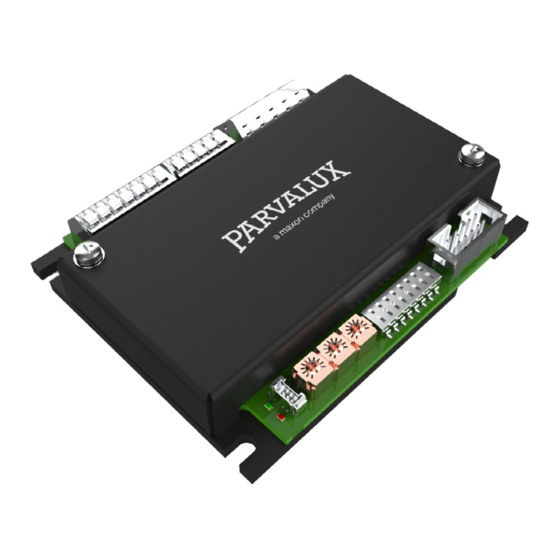
About Specifications About the device Technical data - SC 50/15 servo controller (738590) The «SC 50/15» is a small-sized, powerful 4-quadrant PWM servo controller for the highly efficient control of permanent magnet DC (PMDC) and brushless DC (BLDC) motors up to approximately 750 Watts with various feedback options, such as Hall sensors or incremental encoders. Electrical rating 1 Nominal power supply voltage +V 12 - 50... -
Page 4: Technical Data
Specifications Setup Technical data Important notice: pre-requisites for permission to commence installation The SC 50/15 Servo Controller is considered as partly completed machinery according to EU Directive 2006/42/EC, Article 2, Clause (g) and is intended to be incorporated into or assembled with other machinery or other partly completed machinery or equipment. Environment 1 Temperature - Operation °C... -
Page 5: Recommended Tools
Setup Setup Electrical installation. Power supply requirements 1 Output voltage +Vcc 12 ... 50 VDC 2 Absolute output voltage Min. 10 VDC; max. 56 VDC Depending on load 3 Output current • Continuous max. 15 A • Short-time (acceleration, < 10 s) max. 30 A Table 3-11 Power supply requirements X1 Power supply and motor →page 07 X2 Hall sensor →page 08... - Page 6 Setup Setup Hall sensor Digital inputs 1 ... 3 1 Sensor supply voltage (V 1 Input voltage 0 ... 24 sensor 2 Max. hall sensor supply current 2 Max. input voltage ±30 3 Input voltage 0 ... 24 3 Logic 0 <...
- Page 7 Setup Setup Analog input 1 X3 pin Signal Description 1 Input voltage 0 ... 5.0 Not connected 2 Max. input voltage ±30 Sensor supply voltage (+5 VDC; I ≤100 mA) sensor 3 Input resistance kΩ Typically 87 (0 ... 6.0 VDC), typically 31 (6.0 ... 30.0 VDC) Ground 4 A/D converter Not connected...
- Page 8 Setup Setup SC 50/15 +5.45 V Important: DIP switch settings during «closed loop speed control» In control mode «closed loop speed control» (DIP switch #2 “OFF”), the configurations «PMDC motor» (DIP switch #1 “ON”) and «Hall sensor only» (DIP switches #4…#6 “OFF”) are not valid and the controller will report an error.
- Page 9 Setup Setup Status indicators Wiring The SC 50/15 features a set of LED indicators to display the device status. Ground safety earth connection (optional) SC 50/15 Power supply I/Os 12 ... 50 VDC DigIN1 • Green LED shows the operating status •...
- Page 10 Operation List of figures Operation Figure number Description Page number The «SC 50/15» can operate in two modes: Figure 2-1 Dimensional drawing [mm] • Closed loop speed control compares the actual speed signal with the applied set value. In case of deviation, the speed is dynamically readjusted. •...
- Page 11 BH11 8PU intellectual property rights. +44 1202 512 575 © 2022 Parvalux. All rights reserved. Subject to change without prior notice. www.parvalux.com CCMC | SC 50/15 Hardware Reference | Edition 2022-02 | DocID rel10565 a maxon company | www.maxongroup.com...
Need help?
Do you have a question about the PARVALUX SC 50/15 and is the answer not in the manual?
Questions and answers