
Related Manuals for Bose F1 812


Summary of Contents for Bose F1 812
- Page 1 F1 Model 812 Flexible Array Loudspeaker and F1 Subwoofer ©2016 Bose Corporation Service Manual Reference Number 731419-SM Rev. 03...
-
Page 2: Table Of Contents
Contents Safety Information ..........................3 Warranty ............................. 3 Product Description ........................4-12 Specifications ..........................13-15 Accessories ............................. 15 Electrostatic Discharge Sensitive (ESDS) Device Handling ............. 16 Part List Notes ..........................16 Manufactured Versions ........................16 Packaging Part List, F1 Model 812 Flexible Array Loudspeaker ..........17 Figure 1. -
Page 3: Safety Information
BY AN AUTHORIZED BOSE SERVICE CENTER AND SHALL NOT BE REPRODUCED OR USED FOR ANY OTHER PURPOSE. WARRANTY The Bose F1 Model 812 Flexible Array Loudspeaker and F1 Subwoofer are covered by a limited 2 year warranty on electronics and a 5-year warranty on transducers. -
Page 4: Product Description
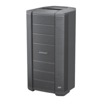
The Bose F1 Subwoofer packs all the power of a larger bass box into a more compact design that’s easier to carry and fits in a car. A mounting stand for the loudspeaker is integrated right into the body of the subwoofer, so you always know where it is, making setup fast and easy. - Page 5 Product Description F1 Model 812 Flexible Array Loudspeaker Carry handle Carry handle Flexible array Connections and controls panel Front LED Front Rear F1 Subwoofer Built-in speaker stand Speaker Speaker stand stand slot slot Carry handle Front LED Connections and controls panel Carry handle AC input connector and power switch...
- Page 6 Product Description Setting Up the System Using the F1 Model 812 with the F1 Subwoofer The built-in loudspeaker stand is integrated into the rear of the subwoofer. Setting up the F1 Model 812 loudspeaker with the F1 subwoofer is a simple three-step process: Locate the stand on the back of the F1 subwoofer.
- Page 7 Product Description Using the Flexible Array You can change the coverage pattern by changing the position of the top and bottom array. Moving the array Pushing an array in Pulling an array out Four coverage patterns Straight array J array Pull top and bottom array out Pull top array out, push bottom array in.
- Page 8 Product Description F1 Model 812 Control Panel POWER: AC AC power power on/off input SIGNAL/CLIP: Displays the input SIGNAL/CLIP: Displays the input signal status in color. signal status in color. • Green = signal present. • Green = signal present. •...
- Page 9 Product Description F1 Subwoofer Control Panel FRONT LED : selector switch: • POWER enables LED to indicate power status. • LIMIT enables LED to indicate limiting. • OFF turns off LED. POWER/FAULT indicates power/fault LINE OUTPUT 1 & 2: status Individual outputs that provide balanced line •...
- Page 10 Product Description Connecting Sources Before plugging in a sound source, turn the VOLUME control of the channel fully counter clockwise. The two independent inputs provide a combination of input connectors that can accomodate microphone and line- level inputs. Note: Only dynamic or self-powered mics can be used for INPUT 1. Setting Up INPUT 1 with a Microphone Turn the INPUT 1 VOLUME fully counter-clockwise.
- Page 11 Product Description Connection Modes Mic to F1 model 812 loudspeaker INPUT 1 Set F1 Model 812 Set F1 Model 812 SIGNAL INPUT EQ to FULL RANGE. MIC. Mobile device to single F1 model 812 loudspeaker Set F1 Model 812 to FULL RANGE. Mobile device headphone output to F1 Model 812 INPUT 2 RCA connectors.
- Page 12 Product Description Connection Modes (continued) Mobile device to F1 model 812 loudspeaker and F1 subwoofer F1 Model 812 F1 Subwoofer Set F1 Model 812 EQ to WITH SUB. Mobile device headphone output to F1 Model 812 INPUT 2 RCA connectors. DJ Console to two F1 Subwoofers and two F1 Model 812 loudspeakers F1 Subwoofer-1 F1 Model 812-1...
-
Page 13: Specifications
Specifications F1 Model 812 Flexible Array Loudspeaker System Performance System Type Self powered, two-way Frequency Response (–3 dB) 52 Hz - 15.5 kHz Frequency Range (–10 dB) 43 Hz - 20 kHz Nominal Dispersion 100° H x 40° V (C-position) Maximum SPL @ 1 m 132 dB SPL (peak) Crossover Frequency... - Page 14 Specifications F1 Subwoofer System Performance System Type Self powered Frequency Response (–3 dB) 40 Hz – 250 Hz Frequency Range (–10 dB) 38 Hz – 250 Hz Nominal Dispersion Omni-directional Maximum SPL @ 1 m 130 dB SPL (peak 6 dB CF) Crossover Frequency 40 –...
-
Page 15: Accessories
Specifications Physical Dimensions Weight F1 Model 812 Loudspeaker 26.1" (665 mm) H x 13.1" (334 mm) W x 14.6" (373 mm) D 44.5 lb (20.2 Kg) F1 Subwoofer 27.0" (688 mm) H x 16.1" (410 mm) W x 17.6" (449 mm) D 55.3 lb (24.9 Kg) F1 system stack 73.5"... -
Page 16: Electrostatic Discharge Sensitive (Esds) Device Handling
ELECTROSTATIC DISCHARGE SENSITIVE (ESDS) DEVICE HANDLING This unit contains ESDS devices. We recommend the following precautions when repairing, replacing or transporting ESDS devices: • Perform work at an electrically grounded work station. • Wear wrist straps that connect to the station or heel straps that connect to conductive floor mats. -
Page 17: Packaging Part List, F1 Model 812 Flexible Array Loudspeaker
PACKAGING PART LIST F1 Model 812 Flexible Array Loudspeaker Item Description Part Qty. Note Number Number PE BAG, F1, SVCE 744265-001S ENDCAP, CARTON, MH, SVCE (FIRST QUALITY) 744264-001S CARTON, MH, SVCE 625285-001S GUIDE, OWNERS, F1 SPKR & F1 SUBWFR (3 LANG.) 740644-0010 GUIDE, OWNERS, F1 SPKR &... -
Page 18: Packaging Part List, F1 Subwoofer
PACKAGING PART LIST F1 Subwoofer Item Description Part Qty. Note Number Number PE BAG ,F1, SVCE 744265-001S ENDCAP, BASS, SVC 745193-001S CARTON, BASS (FIRST QUALITY) 625286-001S GUIDE,OWNERS,F1 SPKR & SUBWFR (3 LANG.) 740644-0010 GUIDE,OWNERS,F1 SPKR & SUBWFR (8 LANG.) 740743-0010 GUIDE,OWNERS,F1 SPKR &... -
Page 19: Main Part List, F1 Model 812 Flexible Array Loudspeaker (Refer To Figure 3)
MAIN PART LIST F1 Model 812 Flexible Array Loudspeaker (refer to Figure 3) Item Description Part Qty. Note Number Number GRILLE, SIDE, MH, SERV 625268-011S KIT, LOGO, ASSY, MH, BLK, SVCE 720197-011S GRILLE, ARRAY, CENTER , SERV 625267-011S GRILLE, ARRAY, SERV 625266-011S SCREW, M4X1.5X11.5L, PH, TAPPING, BLK 757326-011S... - Page 20 MAIN PART LIST (CONT.) F1 Model 812 Flexible Array Loudspeaker (refer to Figure 3) Item Description Part Qty. Note Number Number SHRINK TUBE, AC SWITCH 753068-001S SHRINK TUBE, AC INLET 753069-001S Figure 3. F1 Model 812 Flexible Array Loudspeaker...
-
Page 21: Main Part List, F1 Subwoofer (Refer To Figure 4)
MAIN PART LIST F1 Subwoofer (refer to Figure 4) Item Description Part Number Qty. Note Number WOOFER, 10 INCH, BASS, SVCE 625261-001S FOOT, BOTTOM, BASS, SVCE 625289-011S GRILLE, SUB, SVCE 625269-011S STAND, PLASTIC, SVCE 716548-011S PCB ASSY, DSP – I/O, BASS, SVCE 716571-001S SCREW, FOOT, M4x25 721717-001S... - Page 22 2x 1 2x 7 2x 2 2x 6 Figure 4. F1 Subwoofer Exploded View...
-
Page 23: Electrical Part Lists
ELECTRICAL PART LIST SMPS / Power Amplifier PCB Assembly Resistors Reference Description Vendor Part Note Designator Number CHIP, RES, 240K, OHM, 1%, 1/4W, 1206 QCF041010-2403 CHIP, RES, Anti-Surge, 4.7 OHM, 5%, 1/8W, QCF085021-4708 0805,WK08S, WALSIN GP, CHIP, RES, 10K OHM, 1%, 1/10W, 0603 QCF011030-1002 GP, CHIP, RES., 10K OHM, 1/8W, 1%, 0805 QCF081020-1002... - Page 24 ELECTRICAL PART LIST SMPS / Power Amplifier PCB Assembly Resistors (continued) Reference Description Vendor Part Note Designator Number GP, CHIP, RES., 47K OHM, 1/10W, 1%, 0603 QCF011030-4702 CHIP, RES, 56K, OHM, 1%, 1/4W, 1206 QCF041010-5602 GP, CHIP, RES, 10K OHM, 1%, 1/10W, 0603 QCF011030-1002 CHIP, RES, Anti-Surge, 8.2 OHM, 5%, 1/4W, QCF045011-8208...
- Page 25 ELECTRICAL PART LIST SMPS / Power Amplifier PCB Assembly Resistors (continued) Reference Description Vendor Part Note Designator Number R136 H/I, RESISTOR, 10 OHM, 5%, 1W QVF105000-1000 R137 CHIP, RES, WALSIN, 4.7 OHM, 1%, 1/8W, 0805 QCF081021-4708 R139 GP, CHIP, RES, 10K OHM, 1%, 1/10W, 0603 QCF011030-1002 R140 GP, CHIP, RES., 3.3K OHM, 1/10W, 1%, 0603...
- Page 26 ELECTRICAL PART LIST SMPS / Power Amplifier PCB Assembly Resistors (continued) Reference Description Vendor Part Note Designator Number R183 CHIP, RES, Surge, 39 OHM, 5%, 1/4W, 1206, QCF045012-3909 WK12S, Walsin R184 CHIP, RES, Surge, 39 OHM, 5%, 1/4W, 1206, QCF045012-3909 WK12S, Walsin R185 CHIP, RES, Anti-Surge, 4.7 OHM, 5%, 1/8W,...
- Page 27 ELECTRICAL PART LIST SMPS / Power Amplifier PCB Assembly Resistors (continued) Reference Description Vendor Part Note Designator Number R406 GP, CHIP, RES., 6.8K OHM, 1/10W, 1%, 0603 QCF011030-6801 R407 GP, CHIP, RES., 6.8K OHM, 1/10W, 1%, 0603 QCF011030-6801 R408 CHIP, RES, 2.7K OHM, 1/10W, 1%, 0603 QCF011030-2701 R409 CHIP, RES, 910 OHM, 1%, 1/10W, 0603...
- Page 28 ELECTRICAL PART LIST SMPS / Power Amplifier PCB Assembly Resistors (continued) Reference Description Vendor Part Note Designator Number Rx32 CHIP, RES, 240K, OHM, 1%, 1/4W, 1206 QCF041010-2403 Rx33 CHIP, RES, 240K, OHM, 1%, 1/4W, 1206 QCF041010-2403 Rx34 CHIP, RES, 240K, OHM, 1%, 1/4W, 1206 QCF041010-2403 Rx35 CHIP, RES, Surge, 39 OHM, 5%, 1/4W, 1206,...
- Page 29 ELECTRICAL PART LIST SMPS / Power Amplifier PCB Assembly Capacitors (continued) Reference Description Vendor Part Note Designator Number GP, CHIP, CAP, 0.1uF, 50V, 10%,0805, TYPE X7R PYL456470-1040 GP, CHIP, CAP, 0.1uF, 250V, 10%, 1206, X7 PZL4564F0-1040 CAP, MPRO, 10%, 630V, 85', PPS, 33nF, P=3.5M PLR0394P0-3330 CAP, ELECT, 20%, 400V, 105', CapXon, 15uF, PVE0995K1-1560...
- Page 30 ELECTRICAL PART LIST SMPS / Power Amplifier PCB Assembly Capacitors (continued) Reference Description Vendor Part Note Designator Number CHIP, CAP, 5%, 250V, 1206, NPO, 100pF, 1206, PZL4103F0-1010 TYPE NPO CAP, ELECT, 1000uF, 25V, 20%, 105', 10x20mm PLE099550-1020 CHIP, CAP, 10%, 25V, 1206, X7R, 10uF PZL456450-1060 CAP, MYLAR, P=15MM, 10%, 450V, 1uF PLM0374L0-1050...
- Page 31 ELECTRICAL PART LIST SMPS / Power Amplifier PCB Assembly Capacitors (continued) Reference Description Vendor Part Note Designator Number C141 CAP, ELECT, 20%, 400V, 105', CapXon, 15uF, PVE0995K1-1560 L.ESR10X16MM, PITCH=5MM C142 CHIP, CAP, 1.5nF, 50V, 10%, 0603, X7R PXL456470-1520 C143 CHIP, CAP, 10%, 50V, 0603, X7R, 560pF PXL456470-5610 C144 GP, CHIP, CAP, 0.1uF, 50V, 10%, 0603, TYPE X7R...
- Page 32 ELECTRICAL PART LIST SMPS / Power Amplifier PCB Assembly Capacitors (continued) Reference Description Vendor Part Note Designator Number C421 GP, CHIP, CAP, 0.47uF, 50V, 10%, 0603, TYPE X7R PXL456470-4740 C422 CHIP, CAP, 1.5nF, 50V, 10%, 0603, X7R PXL456470-1520 C426 CHIP, CAP, 4.7nF, 50V, 10%, 0603, X7R PXL456470-4720 C427 GP, CHIP, CAP, 1uF, 16V, 10%, 0603, TYPE X7R...
- Page 33 ELECTRICAL PART LIST SMPS / Power Amplifier PCB Assembly Inductors and Ferrite Beads (continued) Reference Description Vendor Part Note Designator Number COMMON COIL, MIN., 4mH, AT, 1KHz, ET24- SILA17007-4020 SE6043 TRANSFORMER, PQ2625, SEB164, Sunshine TSSA00014-0010 TRANSFORMER, PQ2625, SEB164, Sunshine TSSA00014-0010 TOROID, INDUCTOR, T25*15*10, 70uH, DCR, (1-2), SILA02016-7000 75M (MAX)
- Page 34 ELECTRICAL PART LIST SMPS / Power Amplifier PCB Assembly Diodes (continued) Reference Description Vendor Part Note Designator Number CHIP, DIODE, SMA, TSC, ESH1D-R3G, 15nS, 1A, RCD101003-0010 GP, DIODE, BAV21WS, SOD-323, FAST, RCD100021-0010 SWITCHING TYPE CHIP, DIODE, SMA, TSC, ESH1D-R3G, 15nS, 1A, RCD101003-0010 CHIP, DIODE, SMA, TSC, ESH1D-R3G, 15nS, 1A, RCD101003-0010...
- Page 35 ELECTRICAL PART LIST SMPS / Power Amplifier PCB Assembly Transistors (continued) Reference Description Vendor Part Note Designator Number MOSFET, N-CH, TO220AB, SiHP22N60E, 21A, RHM220600-1001 600V, VISHAY PNP, CHIP, TRANSISTOR, PMBT2907, SOT-23 RCPA02907-0001 N-CHANNEL, MOS, TO-220E, IRFB4227PBF RHM004227-1001 MOSFET, N-CH, TO220AB, SiHP22N60E, 21A, RHM220600-1001 600V, VISHAY NPN, CHIP, TRANSISTOR, PMBT2222, SOT-23...
- Page 36 ELECTRICAL PART LIST SMPS / Power Amplifier PCB Assembly Integrated Circuits (continued) Reference Description Vendor Part Note Designator Number DIP, IC, REGULATOR, ST, L7805CV-DG, TO-220, RHI007805-0001 4%, 5V, 1.5A DIP, IC, REGULATOR, ST, L7905CV-DG, TO-220, RHI007905-0001 4%, 5V, 1.5A IC, OP, AMP, DUAL, 8P, SO-8, NJM4580, IC, OP, RCI004580-0001 AMP, DUAL, 8P IC, OP, AMP, DUAL, 8P, SO-8, NJM4580, IC, OP,...
- Page 37 ELECTRICAL PART LIST SMPS / Power Amplifier PCB Assembly Miscellaneous (continued) Reference Description Vendor Part Qty. Note Designator Number AC POWER JACK, BLACK, JR-101, 50*21.9mm CJPA11002-0010 (Used on subwoofer version) AMP, Gasket, EVA, 38 degree, Natural, Black, IVEA00727-0003 L237.4xW11.5xT2 (Used on subwoofer version) AMP, Gasket, EVA, 38 degree, Natural, Black, IVEA00727-0004 L237.4xW11.5xT2 (Used on subwoofer version)
-
Page 38: F1 Model 812 Input-Output / Dsp Pcb Assembly
ELECTRICAL PART LIST SMPS / Power Amplifier PCB Assembly Miscellaneous (continued) Reference Description Vendor Part Qty. Note Designator Number SHRINKING TUBE, DIA=35, L=40mm, DTB135000-0400 BLK,SA2420, SANYO (Used on subwoofer version) Silicon, Insulator, For, L30.7xW1 HISA00021-0001 SILICON, INSULATOR, L105*W26.5*T0.2 HISA00012-0001 SILICON, INSULATOR, L80*W26.5*T0.2, 5 HISA00013-0001 SILICON, INSULATOR, L80*W26.5*T0.2, 6 HISA00014-0001... - Page 39 ELECTRICAL PART LIST F1 Model 812 Input-Output / DSP PCB Assembly Resistors (continued) Reference Description Vendor Part Note Designator Number CHIP, RES, 20 OHM, 1%, 1/8W, 0805 QCF081020-2009 CHIP, RES, 20 OHM, 1%, 1/8W, 0805 QCF081020-2009 GP, CHIP, RES, 4.99K OHM, 1/10W, 1%, 0603 QCF011030-4991 GP, CHIP, RES, 4.99K OHM, 1/10W, 1%, 0603 QCF011030-4991...
- Page 40 ELECTRICAL PART LIST F1 Model 812 Input-Output / DSP PCB Assembly Resistors (continued) Reference Description Vendor Part Note Designator Number GP, CHIP, RES, 2.4K OHM, 1/10W, 1%, 0603 QCF011030-2401 CHIP, RES, 3.9K OHM, 1/10W, 1%, 0603 QCF011030-3901 GP, CHIP, RES, 47K OHM, 1/10W, 1%, 0603 QCF011030-4702 GP, CHIP, RES, 2.2K OHM, 1/10W, 1%, 0603 QCF011030-2201...
- Page 41 ELECTRICAL PART LIST F1 Model 812 Input-Output / DSP PCB Assembly Resistors (continued) Reference Description Vendor Part Note Designator Number R127 GP, CHIP, RES, 3.3K OHM, 1/10W, 1%, 0603 QCF011030-3301 R128 GP, CHIP, RES, 100 OHM, 1/8W, 1%, 0805 QCF081020-1000 R129 GP, CHIP, RES, 10K OHM, 1%, 1/10W, 0603 QCF011030-1002...
- Page 42 ELECTRICAL PART LIST F1 Model 812 Input-Output / DSP PCB Assembly Resistors (continued) Reference Description Vendor Part Note Designator Number R179 GP, CHIP, RES, 3.3K OHM, 1/10W, 1%, 0603 QCF011030-3301 R180 GP, CHIP, RES, 47K OHM, 1/10W, 1%, 0603 QCF011030-4702 R181 GP, CHIP, RES, 20K OHM, 1/10W, 1%, 0603 QCF011030-2002...
- Page 43 ELECTRICAL PART LIST F1 Model 812 Input-Output / DSP PCB Assembly Capacitors (continued) Reference Description Vendor Part Note Designator Number CAP, MINIT, ELECT, 100uF, 16V, 20%, 105', 5x7, PLE999540-1010 P=2mm CAP, MINIT, ELECT, 100uF, 16V, 20%, 105', 5x7, PLE999540-1010 P=2mm CHIP, CAP, 33pF, 50V, 5%, 0603, TYPE NPO PXL410370-3300 CHIP, CAP, 18pF, 50V, 5%, 0603, TYPE NPO...
- Page 44 ELECTRICAL PART LIST F1 Model 812 Input-Output / DSP PCB Assembly Capacitors (continued) Reference Description Vendor Part Note Designator Number CAP, ELECT, 47uF, 16V, 20%, 105'C, 5x11xP2 PLE099542-4700 GP, CHIP, CAP, 0.1uF, 50V, 10%, 0603, TYPE X7R PXL456470-1040 CHIP, CAP, 10uF, 16V, 10%, 0805, X7R PYL456440-1060 GP, CHIP, CAP, 0.1uF, 50V, 10%, 0603, TYPE X7R PXL456470-1040...
- Page 45 ELECTRICAL PART LIST F1 Model 812 Input-Output / DSP PCB Assembly Capacitors (continued) Reference Description Vendor Part Note Designator Number C117 CAP, MINIT, ELECT, 100uF, 35V, 20%, 105', 8x7, PLE999560-1010 P=3.5, LOW ESR C118 CHIP, CAP, 1000pF, 50V, 5%, 0603, TYPE NPO PXL410370-1020 C119 GP, CHIP, CAP, 0.1uF, 50V, 10%, 0603, TYPE X7R...
- Page 46 ELECTRICAL PART LIST F1 Model 812 Input-Output / DSP PCB Assembly Inductors and Ferrite Beads Reference Description Vendor Part Note Designator Number CHIP, BEAD, 600 OHM, 25%, 100MHZ, SMD, 0805, SCBA08051-6010 DCR0.25 OHM, I>1500MA, IDC=20 GP, CHIP, RES, 0 OHM, 1/8W, 5%, 0805 QCF085020-0000 CHIP, BEAD, 600 OHM, 25%, 100MHZ, SMD, 0805, SCBA08051-6010...
- Page 47 ELECTRICAL PART LIST F1 Model 812 Input-Output / DSP PCB Assembly Diodes (continued) Reference Description Vendor Part Note Designator Number SMD, LED, RED/BLUE, MS-PTB2012CURSBAC, KCD260004-0010 2.0X1.25MM GP, DIODE, SW, LL4148, TELEFUNKEN, SOD80, SMT RCD104148-1010 TYPE SMD, LED, H-0805AA22E008-01, AMBER, 0805, 600- KCD300805-0020 608NM GP, DIODE, SW, LL4148, TELEFUNKEN, SOD80, SMT...
- Page 48 ELECTRICAL PART LIST F1 Model 812 Input-Output / DSP PCB Assembly Transistors (continued) Reference Description Vendor Part Note Designator Number XISTR, PNP, KST92, , SOT-23,TRANSISTOR RCP000092-0001 XISTR, NPN, MMBT3904, SOT-23, LRC, GENERAL RCN003904-0008 PURPOSE AMPLIFIER XISTR, NPN, MMBT3904, SOT-23, LRC, GENERAL RCN003904-0008 PURPOSE AMPLIFIER XISTR, NPN, MMBT3904, SOT-23, LRC, GENERAL...
- Page 49 ELECTRICAL PART LIST F1 Model 812 Input-Output / DSP PCB Assembly Integrated Circuits Reference Description Vendor Part Note Designator Number DC-DC CONVERTER, TI, TPS54331DR, SOIC8 RCI054331-0001 IC, OP AMP, DUAL, 8P, SO-8, NJM2068 RCI002068-0001 IC, OP AMP, DUAL, 8P, SO-8, NJM2068 RCI002068-0001 IC, OP AMP, DUAL, 8P, SO-8, NJM4580 RCI004580-0001...
- Page 50 ELECTRICAL PART LIST F1 Model 812 Input-Output / DSP PCB Assembly Miscellaneous (continued) Reference Description Vendor Part Note Designator Number KNOB, VOLUME, TPE, natural black, H19xOD12 BPKA05082-0001 SLIDE, SWITCH CAP, ABS, Kingfa, GAR, L20xW19xH9 BPOA00090-0001 PUSH+LEVER, SWITCH, RF-1003- MSWA09001- BBC8E2L1C,22.1*22.5*15MM 0010 LIGHT GUIDE, LED/I/O, PC+5%, TiO, BPSA02086-0001...
-
Page 51: F1 Subwoofer Input-Output / Dsp Pcb Assembly
ELECTRICAL PART LIST F1 Subwoofer Input-Output / DSP PCB Assembly Resistors Reference Description Vendor Part Note Designator Number GP, CHIP, RES, 20K OHM, 1/10W, 1%, 0603 QCF011030-2002 CHIP, RES, 100 OHM, 1/4, W, 1%, TF, 1206, DALE, QCF041010-1000 CRCW12061000FRT, E3 GP, CHIP, RES, 10K OHM, 1%, 1/10W, 0603 QCF011030-1002 GP, CHIP, RES, 4.99K OHM, 1/10W, 1%, 0603... - Page 52 ELECTRICAL PART LIST F1 Subwoofer Input-Output / DSP PCB Assembly Resistors (continued) Reference Description Vendor Part Note Designator Number GP, CHIP, RES, 649 OHM, 1/10W, 1%, 0603 QCF011030-6490 GP, CHIP, RES, 2K OHM, 1/10W, 1%, 0603 QCF011030-2001 GP, CHIP, RES, 0 OHM, 1/10W, 5%, 0603 QCF015030-0000 GP, CHIP, RES, 3.3K OHM, 1/10W, 1%, 0603 QCF011030-3301...
- Page 53 ELECTRICAL PART LIST F1 Subwoofer Input-Output / DSP PCB Assembly Resistors (continued) Reference Description Vendor Part Note Designator Number R101 GP, CHIP, RES, 5.1K OHM, 1%, 1/10W, 0603 QCF011030-5101 R102 GP, CHIP, RES, 20K OHM, 1/10W, 1%, 0603 QCF011030-2002 R103 GP, CHIP, RES, 100K OHM, 1%, 1/10W, 0603 QCF011030-1003 R104...
- Page 54 ELECTRICAL PART LIST F1 Subwoofer Input-Output / DSP PCB Assembly Resistors (continued) Reference Description Vendor Part Note Designator Number R165 GP, CHIP, RES, 100K OHM, 1%, 1/10W, 0603 QCF011030-1003 R166 GP, CHIP, RES, 2.4K OHM, 1/10W, 1%, 0603 QCF011030-2401 R167 GP, CHIP, RES, 3.3K OHM, 1/10W, 1%, 0603 QCF011030-3301 R168...
- Page 55 ELECTRICAL PART LIST F1 Subwoofer Input-Output / DSP PCB Assembly Capacitors (continued) Reference Description Vendor Part Note Designator Number CAP, MINIT, ELECT, 100uF, 16V, 20%, 105', 5x7, PLE999540-1010 P=2mm CAP, METAL, MINIATURE, BOX, 5%, 100V, 0.1uF, PLN1373A0-1040 P=5MM, MEM104J100A51 GP, CHIP, CAP, 470pF, 50V, 5%, 0603, NPO PXL410370-4710 CHIP, CAP, 18pF, 50V, 5%, 0603, TYPE NPO PXL410370-1800...
- Page 56 ELECTRICAL PART LIST F1 Subwoofer Input-Output / DSP PCB Assembly Capacitors (continued) Reference Description Vendor Part Note Designator Number GP, CHIP, CAP, 22pF, 50V, 5%, 0603, TYPE NPO PXL410370-2200 CHIP, CAP, 390pF, 50V, 10%, 0603, X7R PXL456470-3910 CHIP, ELECT, 10uF, 16V, SMD, 4x4mm PBE099540-1000 GP, CHIP, CAP, 0.1uF, 50V, 10%, 0603, TYPE X7R PXL456470-1040...
- Page 57 ELECTRICAL PART LIST F1 Subwoofer Input-Output / DSP PCB Assembly Capacitors (continued) Reference Description Vendor Part Note Designator Number C109 CAP, METAL, MINIATURE, BOX, 5%, 100V, 0.1uF, PLN1373A0-1040 P=5MM, MEM104J100A51 C110 GP, CHIP, CAP, 0.1uF, 50V, 10%, 0603, TYPE X7R PXL456470-1040 C111 CHIP, CAP, 10uF, 16V, 10%, 0805, X7R...
- Page 58 ELECTRICAL PART LIST F1 Subwoofer Input-Output / DSP PCB Assembly Ferrite Beads and Inductors Reference Description Vendor Part Note Designator Number CHIP, BEAD, 600 OHM, 25%, 100MHZ, SMD, 0805, SCBA08051-6010 DCR0.25, OHM, I>1500MA, IDC=20 CHIP, BEAD, 600 OHM, 25%, 100MHZ, SMD, 0805, SCBA08051-6010 DCR0.25, OHM, I>1500MA, IDC=20 CHIP, BEAD, 600 OHM, 25%, 100MHZ, SMD, 0805,...
- Page 59 ELECTRICAL PART LIST F1 Subwoofer Input-Output / DSP PCB Assembly Diodes (continued) Reference Description Vendor Part Note Designator Number GP, DIODE, SW, LL4148, TELEFUNKEN, SOD80, RCD104148-1010 SMT TYPE GP, DIODE, SW, LL4148, TELEFUNKEN, SOD80, RCD104148-1010 SMT TYPE DIODE, SW, BAV99, DIODES INC, SOT-23, 3PIN, RCD100099-0010 SMT TYPE DIODE, SW, BAV99, DIODES INC, SOT-23, 3PIN,...
- Page 60 ELECTRICAL PART LIST F1 Subwoofer Input-Output / DSP PCB Assembly Transistors (continued) Reference Description Vendor Part Note Designator Number XISTR, NPN, MMBT3904, SOT-23, LRC, NPN, RCN003904-0008 GENERAL, PURPOSE, AMPLIFIER SMD, MOSFET, N-CH, SOT-363, 2N7002DW, RCM027002-1001 FAIRCHILD SMD, MOSFET, N-CH, SOT-363, 2N7002DW, RCM027002-1001 FAIRCHILD SMD, MOSFET, N-CH, SOT-363, 2N7002DW,...
- Page 61 ELECTRICAL PART LIST F1 Subwoofer Input-Output / DSP PCB Assembly Miscellaneous Reference Description Vendor Part Note Designator Number CON1 XLR Connector, 6P, NCJ6FAV-0, 25*25*24MM CJDA06401-1010 CON2 XLR Connector, 3P, NC3MAAV, 19.8*9.8*24MM CJDA03401-1010 CON3 XLR Connector, 6P, NCJ6FAV-0, 25*25*24MM CJDA06401-1010 CON4 XLR Connector, 3P, NC3MAAV, 19.8*9.8*24MM CJDA03401-1010 CONNECTOR, 3 PIN, P=2.5, White, 90', Normal...
-
Page 62: Disassembly Procedures
DISASSEMBLY PROCEDURES F1 Model 812 Loudspeaker Important Note: The top and rear handles and their inserts are not replaceable for safety reasons. Do not attempt to remove them. They are not stocked as repair parts. Some components internal to the loud- speaker enclosure, such as the internal brackets and the left and right SMPS cover are not replaceable. - Page 63 DISASSEMBLY PROCEDURES Note: The Bose ® logo is attached to the center grille. Replacement center grilles DO NOT come with the logo attached. You will need to either re-use the old logo or order a new one. 3. Logo Removal 3.1 Remove the center grille section using...
- Page 64 DISASSEMBLY PROCEDURES 5.3 Remove the two Faston connectors from the driver. Lift out the driver. Note: Be sure to observe polarity when connecting the new driver. 6. Stand Mount Interface Removal 6.1 Remove the six screws that secure the stand mount to the bottom of the loud- speaker enclosure.
- Page 65 DISASSEMBLY PROCEDURES Re-assembly Note: The four self-tapping screws go in the holes at the top of the enclosure and the eight machine screws are used along the sides. 7.3 Place the loudspeaker onto its back. Remove the stand mount interface using procedure 6.
- Page 66 DISASSEMBLY PROCEDURES 8.2 Locate the LED PCB on the back of the front enclosure section. Refer to the photo at right. Remove the two screws that secure the PCB to the front enclosure. Lift off the PCB assembly. 9. Hall Effect Sensor PCB Removal 9.1 Perform steps 7.1 to 7.5 to remove the front baffle section.
- Page 67 DISASSEMBLY PROCEDURES 10.3 Disconnect the ground connection wire. Retain the nut for re-use. 10.4 Disconnect the three wire harnesses at J1, J2 and J3. Lift off the PCB assembly. 10.5 Remove the two knobs. Remove the five screws and one nut that secure the jacks to the panel.
-
Page 68: F1 Subwoofer
DISASSEMBLY PROCEDURES 11.3 Disconnect the ground connection wire. Retain the nut for re-use. Disconnect the wiring harness at J3. 11.4 Disconnect the AC wiring harness at J1. Disconnect the three wire harnesses at J4, J5 and J7. Note: J4 and J5 are located across the PCB assembly from each other. - Page 69 DISASSEMBLY PROCEDURES 2.2 Pull the bottom edge of the grille away from the speaker, and slide it down until it comes out of the groove at the top of the enclosure. Lift off the grille. 3. LED PCB Removal 3.1 Remove the grille using procedure 2. 3.2 The LED PCB housing is located at the top right corner of the loudspeaker.
- Page 70 DISASSEMBLY PROCEDURES 5.2 Carefully lift the DSP / I-O PCB assembly away from the enclosure. Take care to not damage the gasket. 5.3 Disconnect the ground connection wire. Retain the nut for re-use. 5.4 Disconnect the three wire harnesses at J1, J2 and J3.
- Page 71 DISASSEMBLY PROCEDURES 6.1 Remove the eight screws that secure the SMPS / Amp assembly to the loud- speaker enclosure. Take care to not strip the screw heads. 6.2 Carefully lift the SMPS / Amp assembly away from the enclosure. Take care to not damage the gasket.
-
Page 72: Test Procedures
TEST PROCEDURES F1 Model 812 Loudspeaker F1 Model 812 Control Panel Equipment Required: • Balanced audio signal generator • Balanced input audio signal analyzer / dB meter • Switching Amplifier filter, POWER: AC AC power AP AUX-0025 or equivalent power on/off input •... - Page 73 TEST PROCEDURES • Remove the six screws that secure the I/O - DSP PCB to the enclosure. Disconnect the 10-pin wiring harness at J3. This will remove the I/O -DSP output and allow you to perform the following tests. Leave the other wiring harnesses connected. The I/O - DSP PCB uses the +/- 18VDC output from the SMPS/Amplifier PCB to operate.
- Page 74 TEST PROCEDURES 3.10 Change the Front LED switch to the POWER position. Verify that the Front LED is still lit BLUE. 4. Maximum Input Voltage Test 4.1 Set the Input 1 MIC/LINE switch to the MIC position. Set the Input 1 volume control to MAXIMUM (fully CW).
- Page 75 TEST PROCEDURES 7.6 Verify that the Input 1 Signal/Clip LED lights RED. 7.7 Measure the output level at the Line Out XLR connector. It should be >16dBu, +/-1dB. 8. Maximum Input Voltage Test 8.1 Set the Input 2 volume control to MAXIMUM (fully CW). 8.2 Apply a 1KHz, +6dBu signal to the Input 2 1/4”...
- Page 76 TEST PROCEDURES 11.3 Measure the THD+N output level at the Line Out XLR connector. It should be < 0.1%. 11.4 Apply a 1KHz, -3.0dBu signal to the Input 2 Right RCA Jack. 11.5 Measure the THD+N output level at the Line Out XLR connector. It should be < 0.1%. 12.
- Page 77 TEST PROCEDURES 13. Noise Test 13.1 Short the input jacks at the Input 1 XLR connector and at the Input 2 1/4” TRS jack. Set the Input 1 and Input 2 volume controls to the NOON (12 o’clock) position. 13.2 Measure the output noise level at J4 and J5. It should be <-60dBu, A-Weighted with a 20Hz to 22kHz filter.
- Page 78 You can download a pink noise .mp3 file from the F1 Loudspeaker product page on the Bose Service web site at http://intranet.bose.com/tsg or http://serviceops.bose.com. 16.4 Move the Twiddler array to the Reverse J position. Verify that you can hear a difference in the pink noise response.
-
Page 79: F1 Subwoofer
TEST PROCEDURES 17. Air Leak Test 17.1 Set the Input 1 MIC/LINE switch to LINE. Set the Input 1 volume control to Maximum. 17.2 Apply a balanced 48Hz, 55 mVrms sine wave to the Input 1 XLR connector. 17.3 Sweep the input frequency from 48Hz to 60Hz. Listen for air leaks around the cabinet gaskets. - Page 80 TEST PROCEDURES 1.4 Change the Front LED switch to the OFF position. Verify that the front LED is now OFF. 1.5 Change the Front LED switch to the LIMIT position. Leave it in this position for the following tests. You will be checking it for proper operation during these tests. 1.6 Turn the AC power switch OFF.
- Page 81 TEST PROCEDURES 3.8 Measure the output level at the Input 1 Line Output connector. It should be equal to the input signal level, +/- 1 dB. 4. Maximum Input Voltage Test 4.1 Apply a balanced 1 kHz, +24 dBu signal to the Input 1 XLR connector. 4.2 Measure the THD+N level at the Input 1 Line Output connector.
- Page 82 TEST PROCEDURES • Remove the eight screws that secure the SMPS / Amplifier PCB to the enclosure. Disconnect the wiring harnesses from connectors J4 and J5. This will disconnect the woofers from the amplifier outputs. Ensure all other wiring harnesses are connected. CAUTION: You MUST disconnect the AC line cord from the unit when connecting the driver wiring harnesses to the amplifier PCB outputs at J4 and J5 below.
- Page 83 TEST PROCEDURES 8.3 Measure the output gain and THD+N levels at the J4 (upper woofer) and J5 (lower woofer) connectors. Ensure they are as specified in the below table. Input J4 (Upper Woofer) J5 (Lower Woofer) Frequency Output Levels Output Levels 20 Hz Bass Out <...
- Page 84 TEST PROCEDURES IMPORTANT NOTE: Reconnect the wiring harnesses to J4 and J5 on the SMPS / Amplifier PCB before beginning the below tests. This will allow output from the woofers. CAUTION: You MUST disconnect the AC line cord from the unit when connecting the driver wiring harnesses to the amplifier PCB outputs at J4 and J5 below.
-
Page 85: Hi-Pot Test
TEST PROCEDURES Hi-Pot Test THIS IS A MANDATORY TEST Note: If an the unit under test requires disassembly as part of the repair, it MUST be Hi-Pot tested before being returned to the customer to ensure that there is no potential shock hazard. This test requires a Hi-Pot tester with a ground bond attachment to perform this test. -
Page 86: Software Update Procedure
You will need to download and install the Updater software to your laptop or PC. The software is located on the F1 Model 812 and F1 Subwoofer product page on the Bose Service web sites. The link to the F1 Loudspeaker product page is located on the Professional Products page. - Page 87 SOFTWARE UPDATE PROCEDURE 2.2 Once the .zip file is extracted, Double click “Update_Tool.exe” to run the F1 Loudspeaker updater program. Note: Microsoft .NET v4.5.1 or newer is required for the Update Tool to run. If the below alert dialog box is received, update Microsoft.NET. If the tool does not run with the following error: Verify that the Aardvark.dll file is in the same directory as the Update_Tool.exe file.
- Page 88 SOFTWARE UPDATE PROCEDURE 3.2 Double-click the Update_Tool.exe to open the program. 3.3 Once the program is open and with the Aardvark USB and all cabling connected to the loudspeaker, Click on the Refresh Button in the program. See below. This is needed to activate the Aardvark I2C/SPI adapter.
- Page 89 SOFTWARE UPDATE PROCEDURE F1 Subwoofer DSP Panel: 1. Power on the Loudspeaker by turning on the AC power switch. 2. Turn the VOLUME control OFF. 3. Set the POLARITY switch to REV. 4. Verify that the Updater cable is connected to the INPUT 1 XLR connectors;...
- Page 90 SOFTWARE UPDATE PROCEDURE 5.2 Click on the Browse image button to select a new software revision to be loaded. Browse to the location of the update file you wish to load. Click on the file name. The revision level of the new software File FW version will then be shown. 5.3 Click on the Burn Image button to the new revision of software into the F1 Loudspeaker.
-
Page 91: Troubleshooting
Troubleshooting If you experience problems while using this product, try the following solutions. The recommended troubleshooting tools include a spare AC power cord and extra XLR and 1/4” phone plug cables. Problem What to do Loudspeaker is plugged in, • Make sure the power cord is fully engaged into both the F1 Model 812 loudspeaker and the AC outlet. power switch is on, but power •... -
Page 92: Service Manual Revision History
Service Manual Revision History Date Revision Description of Change Change Driven By Pages Level Affected 8/15 Document released at revision 00. Service manual release 9/15 - Added new Hi-Pot test requirements Test spec change - Added new disassembly steps New process 1/16 Subwoofer foot and woofer screw part New part number... - Page 93 SPECIFICATIONS AND FEATURES SUBJECT TO CHANGE WITHOUT NOTICE Bose Corporation The Mountain Framingham Massachusetts USA 01701 P/N: 731419-SM Rev. 03; 3/2016 (P) http://serviceops.bose.com...
Need help?
Do you have a question about the F1 812 and is the answer not in the manual?
Questions and answers