
Related Manuals for Bose F1 812P


Summary of Contents for Bose F1 812P
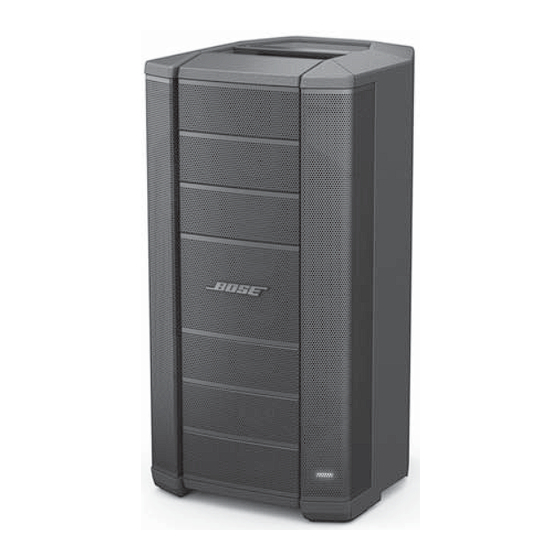
- Page 1 F1 Model 812P Flexible Array Loudspeaker ©2016 Bose Corporation Service Manual Reference Number 374847-SM Rev. 00...
-
Page 2: Table Of Contents
THE PURPOSE OF SERVICING THE IDENTIFIED BOSE PRODUCT BY AN AUTHORIZED BOSE SERVICE CENTER AND SHALL NOT BE REPRODUCED OR USED FOR ANY OTHER PURPOSE. WARRANTY The Bose F1 Model 812P Flexible Array Loudspeaker is covered by a limited 5-year warranty. -
Page 3: Product Description
Key Features FLEX array: Bose exclusive flexible baffle can be configured into four unique shapes, • allowing you to choose the best possible coverage pattern for the application Eight-driver mid/high line array: Eight vertically mounted drivers, each mounted on a custom •... - Page 4 Product Description Using the F1 Model 812 Passive on a Tripod Stand The bottom of the F1 Model 812 Passive loudspeaker includes pole cup for mounting the loud- speaker on a tripod speaker stand. The pole cup fits a standard 35 mm post. WARNING: The F1 Model 812 Passive loudspeaker is not compatible with the stand provided with the F1 Subwoofer.
- Page 5 Recommended Signal Processing Digital signal processing (DSP) equipment is required for infrasonic protection and amplifier power limiting functions. This processing is available in optional products from Bose such as the PowerMatch amplifiers and/or ControlSpace DSP hardware.
-
Page 6: Specifications
Specifications System Performance System Type Two-way Frequency Response (-3 dB) 56 Hz - 16 kHz Frequency Range (-10 dB) 47 Hz - 20 kHz Nominal Dispersion 100° H x 40° V (C-position) Maximum SPL @ 1 m 121 dB SPL (127 dB SPL peak) Sensitivity (SPL / 1 W @ 1 m) 95 dB SPL Long-term Power Handling... -
Page 7: Packaging Part List, F1 Model 812P Loudspeaker
PACKAGING PART LIST F1 Model 812P Loudspeaker Item Description Part Number Qty. Note Number GUIDE, OWNERS, F1 SPEAKER, PASSIVE, SVC 740742-001S CARTON ENDCAP, MH, SVCE 744264-001S BAG, PACKING, PE, F1 744265-001S CARTON, MH PASSIVE, SVCE 745849-0010 Figure 1. F1 Model 812 Packing View... -
Page 8: Main Part List, F1 Model 812P Loudspeaker
MAIN PART LIST F1 Model 812P Loudspeaker (refer to Figure 2) Item Description Part Number Qty. Note Number SCREW, M4x25, PH, BLK 721717-001S (FOOT, WOOFER, TWID ARRAY PLASTIC) SCREW, M4x20, FH, BLK GASKET, STAND MOUNT INTERFACE, SVCE 628346-001S POLE MOUNT INTERFACE, PASSIVE, MH, SVCE 757437-011S FOOT, FRONT LEFT, MH, SERV 625288-011S... - Page 9 MAIN PART LIST (CONT.) F1 Model 812P Loudspeaker (refer to Figure 3) Item Description Part Number Qty. Note Number BAFFLE, WOOFER NUT, M4 LENS, LED, SVCE 720413-001S LIGHT GUIDE, LED, SVCE 720414-001S SCREW, TAPPING, M3x5.84, PH M4 INSERT ASSY, POSITIONING MAGNET, SERV 628066-001S SCREW, TAPPING, M3x7.5, PH, BLK ASSY, ARRAY, FLEX, PASSIVE (REFER TO ITEMS 54...
- Page 10 MAIN PART LIST (CONT.) F1 Model 812P Loudspeaker (refer to Figure 4) Item Description Part Number Qty. Note Number M4 INSERT ENCLOSURE, REAR, MH HANDLE, REAR, MH SCREW, M6-1.0x25, SHCS M6 FLAT WASHER M6 LOCK WASHER M6 NUT M3 INSERTS, 5.6MM, L M3 INSTERS, 10.4MM, L GASKET, ENCLOSURE, UPPER, REAR GASKET, ENCLOSURE, LEFT...
- Page 11 MAIN PART LIST (CONT.) F1 Model 812P Loudspeaker (refer to Figure 5) Item Description Part Number Qty. Note Number SCREW, M4x1.5x11.5L, PH, TAPPING, BLK 757326-011S GRILLE, ARRAY, SERV 625266-011S TWIDDLER 2.5IN NEO TXX SERV 625262-001S BAFFLE, ARRAY COVER, ARRAY, MH, SERV 625273-011S BRACKET, ARRAY COVER SCREW, ARRAY COVER...
-
Page 12: Electrical Part List, Crossover Pcb Assembly
ELECTRICAL PART LIST Crossover PCB Assembly Reference Description Qty. Vendor Part Note Designator Number MKT Polyester Film CAP 6.2UF 160V +-5% MKT Polyester Film CAP 22UF 100V +-5% 2.2MH N/A 1KHZ DIP Laminated Core Inductor 2.7MH N/A 1KHZ DIP Laminated Core Inductor RXE 250 PTC MAX 0.08OHM 40A G WIRE JUMPER NEUTRIK SPEAKON CNT. -
Page 13: Disassembly Procedures
DISASSEMBLY PROCEDURES F1 Model 812P Loudspeaker Important Note: The top and rear handles and their inserts are not replaceable for safety reasons. Do not attempt to remove them. They are not stocked as repair parts. Some components internal to the loud- speaker enclosure, such as the internal brackets are not replaceable. - Page 14 DISASSEMBLY PROCEDURES Note: The Bose logo is attached to the ® center grille. Replacement center grilles DO NOT come with the logo attached. You will need to either re-use the old logo or order a new one. 3. Logo Removal 3.1 Remove the center grille section using...
- Page 15 DISASSEMBLY PROCEDURES 6. Stand Mount Interface Removal 6.1 Remove the six screws that secure the stand mount to the bottom of the loud- speaker enclosure. 6.2 Carefully lift the stand mount interface away from the loudspeaker enclosure. Take care to not damage the mount interface gasket.
- Page 16 DISASSEMBLY PROCEDURES 7.3 Place the loudspeaker onto its back. Remove the stand mount interface using procedure 6. 7.4 Once the screws are removed, you are ready to separate the woofer baffle from the loudspeaker enclosure. Separate the front section of the enclosure from the rear section by pulling them apart at the opening left by the removal of the stand mount interface.
- Page 17 DISASSEMBLY PROCEDURES 8. Input Panel / Crossover PCB Assembly Removal 8.1 Remove the six screws that secure the Crossover PCB assembly to the loud- speaker enclosure. Re-assembly Note: The two longer screws should be reinstalled in the bottom two holes. 8.2 Carefully lift the Crossover PCB assem- bly away from the enclosure.
-
Page 18: Test Procedures
TEST PROCEDURES F1 Model 812P Loudspeaker 1. Air Leak Test 1.1 Apply a 22 Vrms, 48 Hz sine wave to the Equipment Required: • Audio signal generator Channel 1 input. • Neutrik NL4 cable or Spade Lug cable • Audio amplifier 1.2 Sweep the input frequency from 48 Hz to 60 Hz. - Page 19 TEST PROCEDURES Noise type Tick Periodic im pulse noise audible when within 2ft of source extraneous hum m ing sound at fundam ental caused by vibration. Often from a vibe low level grille or panel vibration buzz low low level buzz heard within 5ft and not audible with m usic as not heard during a level "fast"...
-
Page 20: Service Manual Revision History
Service Manual Revision History Date Revision Description of Change Change Driven By Pages Level Affected 5/16 Document released at revision 00. Service manual release... - Page 21 SPECIFICATIONS AND FEATURES SUBJECT TO CHANGE WITHOUT NOTICE Bose Corporation The Mountain Framingham Massachusetts USA 01701 P/N: 374847-SM Rev. 00; 5/2016 (P) http://serviceops.bose.com...
Need help?
Do you have a question about the F1 812P and is the answer not in the manual?
Questions and answers