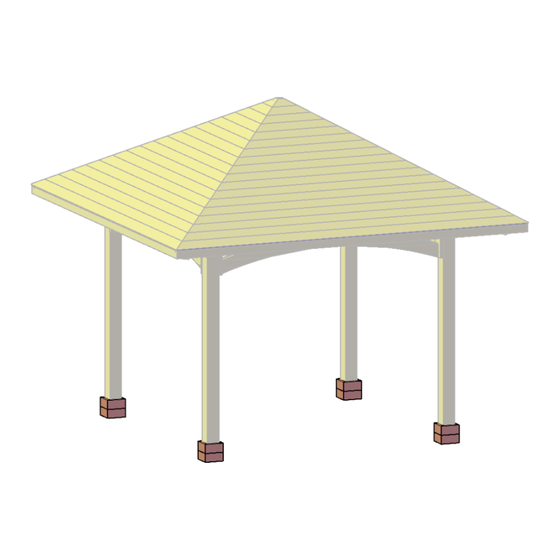
Summary of Contents for Forever Redwood THE LORETO PAVILION
- Page 1 866.332.2403 (TOLL FREE); 7am – 7pm Pacific Time, Monday-Saturday ASSEMBLY INSTRUCTIONS FOR THE LORETO PAVILION...
- Page 2 P| 1 THE LORETO PAVILION www.ForeverRedwood.com...
- Page 3 P| 2 THE LORETO PAVILION www.ForeverRedwood.com...
- Page 4 P| 3 THE LORETO PAVILION www.ForeverRedwood.com...
- Page 5 P| 4 THE LORETO PAVILION www.ForeverRedwood.com...
- Page 6 Step 2: Attach the single supports (2) to the posts with 3/8´´ X 6´´ lag bolts (C). Each part has a series of numbers that indicate where to attach the part with the corresponding number. 3/8´´ X 6´´ Lag bolts P| 5 THE LORETO PAVILION www.ForeverRedwood.com...
- Page 7 3/8´´ X 6´´ Lag bolts 3/8´´ X 10´´ Lag bolts Step 4: Attach the single supports (2) to the supports with in-between blocking (3) with 3/8´´ x 7 ½´´ bolts (E). 3/8´´ X 7 ½´´ Bolts P| 6 THE LORETO PAVILION www.ForeverRedwood.com...
- Page 8 5/16´´ X 15´´ Bolts 5/16´´ X 3´´ Lag bolts Step 6: Attach the metal plaques (12) to the supports at their corner (2,3) with 5/16´´ x 3´´ lag bolts (B). 5/16´´ X 3´´ Lag bolts P| 7 THE LORETO PAVILION www.ForeverRedwood.com...
- Page 9 5/16´´ x 3 ½´´ bolts (H). Each part has a series of numbers that indicate where to attach the part with the corresponding number. 3/8´´ X 6´´ Lag bolts 5/16´´ X 3 ½´´ Lag bolts P| 8 THE LORETO PAVILION www.ForeverRedwood.com...
- Page 10 Step 10: Attach the rafters (8) to the diagonal rafters (7) with 3´´ deck screws (J) and to the single supports with 3/8´´ x 10´´ lag bolts (D). Each part has a series of numbers that indicate where to attach the part with the corresponding number. 3´´ Deck screws 3/8´´ X 10´´ Lag bolts P| 9 THE LORETO PAVILION www.ForeverRedwood.com...
- Page 11 Step 12: Use 8´´ x 2 ½´´ deck screws (L) to attach the fascia boards (9) to the rafters, central rafters and diagonal rafters. Each part has a series of numbers that indicate where to attach the part with the corresponding number. 2 ½´´ Deck screws P| 10 THE LORETO PAVILION www.ForeverRedwood.com...
- Page 12 Each part has a series of numbers that indicate where to attach the part with the corresponding number 1 5/8´´ X 6´´ Deck screws Step 14: Finally, use 3´´ deck screws (J) to attach the boots (11) to each posts. 8´´ X 3´Deck Screws P| 11 THE LORETO PAVILION www.ForeverRedwood.com...
- Page 13 This completes the Pavilion assembly. Hope you enjoy your set for many decades. If you ever have a problem or a question, don't hesitate to call us (866 332 2403) or email us. We are here to support you. P| 12 THE LORETO PAVILION www.ForeverRedwood.com...
- Page 14 HOW TO REMOVE THE ELECTRICAL WIRING TRIM FROM THE POST: Step 1: First remove the deck screws to remove the boots of the post. Don´t add the lag bolt over the trim piece initially. Step 2: Remove the arcs of the Pavilion. P| 13 THE LORETO PAVILION www.ForeverRedwood.com...
- Page 15 Step 3: Remove the trim. Note: The dimensions of the trim are standard, adjust if necessary. P| 14 THE LORETO PAVILION www.ForeverRedwood.com...


Need help?
Do you have a question about the THE LORETO PAVILION and is the answer not in the manual?
Questions and answers