Table of Contents
Advertisement
Quick Links
Advertisement
Table of Contents

Related Manuals for VARSITY Scoreboards FB-15


Summary of Contents for VARSITY Scoreboards FB-15
- Page 1 MODEL FB-15 Installation & Operation Manual...
- Page 2 MODEL FB-15 INSTALLATION WARRANTY This product is warrantied against defects in materials and workmanship for the period specified in the warranty from the date of invoice. SERVICE Technical support is available 24 hours a day, 7 days a week. 1-800-411-3136 https://www.varsityscoreboards.com/support/contact-support.html...
- Page 3 A NOTE TO INSTALLERS If you are installing this segment timer for a client, please return the manual to the individual in charge of the segment timer upon completion of installation. SEGMENT TIMER DIMENSIONS 6.8’ wide x 2.3’ tall x 8” deep...
-
Page 4: Table Of Contents
TABLE OF CONTENTS INSTALLATION OVERVIEW PRODUCT SPECIFICATIONS CONNECTING THE CABLES CONTROLLER DEFINITIONS 10-12 GETTING STARTED CONFIGURATION MODE PARAMETER 0: TIMER FUNCTION PARAMETER 1: NUMBER OF TIMER DIGITS PARAMETER 2: NUMBER OF CLOCK DIGITS PARAMETER 3: FIRST CLOCK DIGIT VALUE PARAMETER 4: HORN LENGTH PARAMETER 5: COUNT UP / COUNT DOWN PARAMETER 6: 12-HOUR / 24-HOUR CLOCK FORMAT TIMER OPERATION... - Page 5 MODEL FB-15 INSTALLATION Please inspect all shipping containers upon arrival for damage and ensure that you have all of the parts listed below: ITEMS IN LARGE PACKAGE(S) (1) 6 8’ x 2 3’ Football Segment Timer Shipped in (1) section...
- Page 6 Note “DAMAGED” on the Delivery Receipt Form, including details of the type of damage to the freight and packaging. Ask the delivery driver to call the local terminal and report immediately. Contact Varsity Scoreboards immediately while the delivery driver is still present to report the damage A. Phone number B.
-
Page 7: Installation Overview
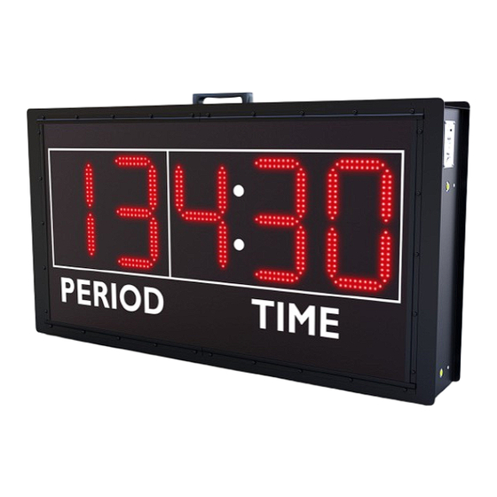
INSTALLATION OVERVIEW The FB15 is a 5-digit sports timer designed to count up or down. The timer is completely user- programmable and allows the user to set the number of clock digits, the “weight” of the digits, whether the timer counts up or down, the length of the horn sounding, and several other features. The FB15 is shipped from the factory configured as a 2-segment / 3-clock digit count down timer. -
Page 8: Product Specifications
PRODUCT SPECIFICATIONS OVERALL DIMENSIONS WEIGHT 6.8’ W x 2.3’ H x 8” D - shipped in one (1) section Hanging weight = approximately 55 lbs Shipping weight = approximately 90 lbs INSTALLATION RECOMMENDATIONS Installation hardware not supplied. Check local code for requirements. Anchors, bolts, chains, cables and related hardware must meet minimum weight requirements. -
Page 9: Connecting The Cables
CONNECTING THE CABLES NOTE: The segment timer is equipped to operate on a 110-volt external AC power, or rechargeable external battery power, using the supplied 10-volt wall transformer. Some units are additionally equipped with an internal rechargeable battery. To power the segment timer using the AC adapter, plug one end into the receptacle on the unit’s switch plate labeled “AC POWER.”... - Page 10 CONTROLLER DEFINITIONS THE HANDHELD SEGMENT TIMER CONTROLLER...
-
Page 11: Controller Definitions
CONTROLLER DEFINITIONS CONTROLLER DEFINITIONS 9 / -1 Guest 1 / Power 5 / Set Clock Not applicable with this Turns Controller on/off. Sets the clock. Hold down for model. 3 seconds until the display clears. Enter the desired time 2 / LED Indicator 10 / Horn Key in a four-digit format using Indicates power and network... - Page 12 CONTROLLER DEFINITIONS THE BACK 14 / DIN Socket COMMUNICATION For DIN cables. CABLE: Connect the provided 5-pin DIN cable to the handheld controller and then to the provided junction box cover plate assembly. 15 / Battery Access Panel Uses 4 AA Batteries. Batteries are not rechargeable.
-
Page 13: Getting Started
GETTING STARTED CONFIGURING THE SEGMENT TIMER The FB-15 is shipped from the factory configured as follows: 2-Digit segment timer with a 3-digit clock. Periods set to count-down. 3-Second horn when a user-preset time is reached. NOTE: This is the most commonly used configuration for this mode. If this factory configuration suits your needs, there is no need to further configure this display. -
Page 14: Configuration Mode
CONFIGURATION MODE Before switching the segment timer to configuration mode, ensure that the handheld controller is properly connected to the timer. To place the timer in configuration mode: Turn the timer’s “POWER” switch to the appropriate “ON” position. Press the “9” key within one second of turning the timer’s power on. Press the “7”... -
Page 15: Parameter 0: Timer Function
PARAMETER 0: TIMER FUNCTION PERIOD TIMER SETTING Press the “1” to configure the unit as a period timer. A “1” will be displayed in the last digit. Set Parameters 1-5 then skip to the “Timer Operation” section of the manual. You can scroll forward and backward through the Parameters to be set for the function you specified by using the “NEXT”... -
Page 16: Parameter 2: Number Of Clock Digits
PARAMETER 2: NUMBER OF CLOCK DIGITS This feature is available when Parameter “0” is set to “1” or “3.” Use the number keys on the handheld controller to enter the desired number of clock digits. This value may be from “1” to “10,” but the timer will not accept a value greater than the number of timer digits set in Parameter ‘1”... -
Page 17: Parameter 3: First Clock Digit Value
PARAMETER 3: FIRST CLOCK DIGIT VALUE This feature is available when Parameter “0” is set to “1” or “3.” Possible values for this Parameter are shown in the table below: First Clock Digit Value Settings Setting Description Days 10’s [ XX:XX:XX:XX.XX ] Days 1’s [ X:XX:XX:XX.XX ] Hours 10’s [ XX:XX:XX.XX ] Hours 1’s [ X:XX:XX.XX ]... -
Page 18: Parameter 4: Horn Length
PARAMETER 4: HORN LENGTH This feature is only available when Parameter “0” is set to “1.” Use the number keys on the handheld controller to specify how long the horn will sound in seconds. PARAMETER 5: COUNT UP / COUNT DOWN This feature is only available when Parameter “0”... -
Page 19: Timer Operation
TIMER OPERATION COUNT-UP FUNCTION When the unit is configured to count up (set in Parameter “5”) a user-preset stopping time may be entered but is optional. If a user-preset stopping time is entered and the timer is started, the timer will begin counting up from zero and stop at the user-preset stopping time. - Page 20 TIMER OPERATION EXAMPLE OPERATION If Parameter 2 was set to 3 (3 clock digits), Parameter 3 was set to 6 (first clock digit value), Parameter 5 was set to 0 (count-down) and the desired segment time is 5 minutes, the segment time would be entered by pressing a four-digit entry.
-
Page 21: Time Of Day Operation
TIME OF DAY OPERATION CONFIGURATION REQUIREMENTS If the unit was configured as a time of day display (see Parameter “0: Timer Function” section) the following Parameters must also be set to the specified value before the timer can be used as a time of day display: Time of Day Parameter Requirements Parameter...
Need help?
Do you have a question about the FB-15 and is the answer not in the manual?
Questions and answers