Table of Contents
Advertisement
Advertisement
Table of Contents

Related Manuals for VARSITY Scoreboards MS4


Summary of Contents for VARSITY Scoreboards MS4
- Page 1 MODEL MS4 Installation & Operation Manual...
- Page 2 MODEL MS4 INSTALLATION WARRANTY This product is warrantied against defects in materials and workmanship for the period specified in the warranty from the date of invoice. SERVICE Technical support is available 24 hours a day, 7 days a week. 1-800-411-3136 https://www.varsityscoreboards.com/support/contact-support.html...
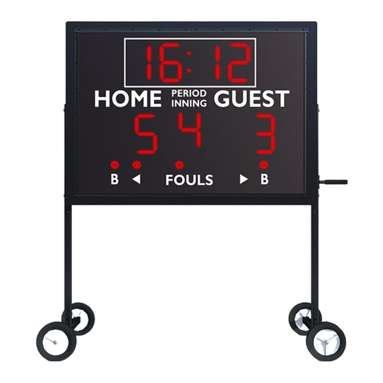
- Page 3 A NOTE TO INSTALLERS If you are installing this scoreboard for a client, please return the manual to the individual in charge of the scoreboard upon completion of installation. SCOREBOARD DIMENSIONS 52” wide x 38” tall x 8” deep...
-
Page 4: Table Of Contents
TABLE OF CONTENTS INSTALLATION OVERVIEW PRODUCT SPECIFICATIONS LEG ASSEMBLY INSTALLATION 9-11 POWERING THE MS4 CONTROLLER DEFINITIONS GETTING STARTED BASIC KEYPAD FUNCTIONS BASKETBALL OPERATION FOOTBALL OPERATION BASEBALL OPERATION SOCCER OPERATION VOLLEYBALL OPERATION WRESTLING OPERATION TENNIS OPERATION TRACK OPERATION TIMED WORKOUT OPERATION... - Page 5 MODEL MS4 INSTALLATION Please inspect all shipping containers upon arrival for damage and ensure that you have all of the parts listed below: ITEMS IN LARGE PACKAGE(S) (1) 52” x 38” Multisport Scoreboard Shipped in (1) section...
- Page 6 Note “DAMAGED” on the Delivery Receipt Form, including details of the type of damage to the freight and packaging. Ask the delivery driver to call the local terminal and report immediately. Contact Varsity Scoreboards immediately while the delivery driver is still present to report the damage A. Phone number B.
-
Page 7: Installation Overview
INSTALLATION OVERVIEW BEFORE OPERATING Review the product specifications below to determine your specific installation hardware. Mount scoreboard to leg assembly Run and connect electrical service to the scoreboard. Test the installed system. -
Page 8: Product Specifications
PRODUCT SPECIFICATIONS OVERALL DIMENSIONS WEIGHT 52” W x 38” H x 8” D - shipped in one (1) section Hanging weight = approximately 90 lbs Shipping weight = approximately 125 lbs INSTALLATION RECOMMENDATIONS Check local code for requirements. Anchors, bolts, chains, cables and related hardware must meet minimum weight requirements. -
Page 9: Leg Assembly Installation
LEG ASSEMBLY INSTALLATION (1) Pipe Handle 1/2” x 6” (4) RIVNUT 1/4-20 GRP 027- 1 65 RIB (2) Bolt 1/4-20 X 1 GR 5 (2) Leg Welded Assembly Zinc Hex (4) Washer 3/8” Split Lock (4) Bushing Reducer 1/2” (4) Bolt 3/8-16X2-1/2 Zinc Axle 5/8”... - Page 10 LEG ASSEMBLY INSTALLATION Attach the 8” wheels to the leg that has the factory-installed threated wheel inserts. Use the provided 1/2’ hardware to do so. See image below.
- Page 11 LEG ASSEMBLY INSTALLATION Attach the legs to the MS-4 cabinet using the provided 3/8” hardware. 3/8-16UNC X 2-1/2" BOLTS, WASHERS HANDLE WHEEL 1/4-20UNC X 1" BOLTS, WASHERS 1/2" BUSHING 1/2-13UNC X 3" BOLTS...
-
Page 12: Powering The Ms4
POWERING THE MS4 NOTE: The scoreboard is equipped to operate on a 110-volt external AC power, or rechargeable external battery power, using the supplied 10-volt wall transformer. Some units are additionally equipped with an internal rechargeable battery. To power the scoreboard using the AC adapter, plug one end into the receptacle on the unit’s switch plate labeled “AC POWER.”... -
Page 13: Controller Definitions
CONTROLLER DEFINITIONS THE BACK 1 / DIN Socket COMMUNICATION For DIN cables. CABLE: Connect the provided 5-pin DIN cable to the handheld controller and then to the provided junction box cover plate assembly. 2 / Battery Access Panel Uses 4 AA Batteries. Batteries are not rechargeable. -
Page 14: Getting Started
GETTING STARTED CHANGING GAME MODES Since this scoreboard is designed to score several different sports, it has several different modes- one for each sport that it is capable of scoring. Each game mode also has a corresponding keypad insert that helps the operator identify which keys to press for which function. When the scoreboard is first turned ON, a number appears briefly in the “HOME”... -
Page 15: Basic Keypad Functions
BASIC KEYPAD FUNCTIONS SETTING THE CLOCK Press and hold the “SET CLOCK” key for three seconds. After the clock’s display clears, use the number keys to enter the desired period time in a four-digit format. Example: to enter a period time of 8:00, press “0, 8, 0, 0.” To enter a period time of 12:00, press “1, 2, 0, 0.”... -
Page 16: Basketball Operation
BASKETBALL OPERATION GETTING STARTED Put the scoreboard into “BASKETBALL” mode. Make sure the “BASKETBALL” keypad insert is in the controller. HOME AND GUEST SCORING HOME SCORE GUEST SCORE To add one to “HOME,” press the “HOME SCORE” To add one to “GUEST,” press the “GUEST key once. -
Page 17: Football Operation
FOOTBALL OPERATION GETTING STARTED Put the scoreboard into “FOOTBALL” mode. Make sure the “FOOTBALL” keypad insert is in the controller. HOME AND GUEST SCORING HOME SCORE GUEST SCORE To add one to “HOME,” press the “HOME SCORE” To add one to “GUEST,” press the “GUEST key once. -
Page 18: Baseball Operation
BASEBALL / SOFTBALL OPERATION GETTING STARTED Put the scoreboard into “SOFTBALL” or “BASEBALL” mode. Make sure the appropriate “SOFTBALL” or “BASEBALL” keypad insert is in the handheld controller. NOTE: “SOFTBALL” mode has the same functions as “BASEBALL” mode, with a four-digit clock. In “SOFTBALL”... -
Page 19: Soccer Operation
SOCCER OPERATION GETTING STARTED Put the scoreboard into “SOCCER” mode. Make sure the “SOCCER” keypad insert is in the controller. NOTE: This scoring mode and insert can also be used for “HOCKEY/F. HOCKEY” and “WATER POLO.” HOME AND GUEST SCORING HOME SCORE GUEST SCORE To add one to “HOME,”... -
Page 20: Volleyball Operation
VOLLEYBALL OPERATION GETTING STARTED Put the scoreboard into “VOLLEYBALL” mode. Make sure the “VOLLEYBALL” keypad insert is in the controller. HOME AND GUEST SCORING HOME SCORE GUEST SCORE To add one to “HOME,” press the “HOME SCORE” To add one to “GUEST,” press the “GUEST key once. -
Page 21: Wrestling Operation
WRESTLING OPERATION GETTING STARTED Put the scoreboard into “WRESTLING” mode. Make sure the “WRESTLING” keypad insert is in the controller. HOME AND GUEST MATCH SCORING HOME MATCH SCORE GUEST MATCH SCORE To add one to “HOME MATCH SCORE,” press the To add one to “GUEST MATCH SCORE,”... -
Page 22: Tennis Operation
TENNIS OPERATION GETTING STARTED Put the scoreboard into “TENNIS” mode. Make sure the “TENNIS” keypad insert is in the controller. LEFT AND RIGHT GAME SCORE LEFT GAME SCORE RIGHT GAME SCORE To increase the “LEFT GAME SCORE,” press the To increase the “RIGHT GAME SCORE,” press the “LEFT GAME SCORE”... -
Page 23: Track Operation
TRACK / COUNT-UP OPERATION GETTING STARTED Put the scoreboard into “TRACK” mode. Make sure the “TRACK” keypad insert is in the controller. NOTE: In “TRACK (COUNT UP)” mode, when the clock is started the time will be display in minutes and seconds. -
Page 24: Timed Workout Operation
TIMED WORKOUT OPERATION GETTING STARTED Put the scoreboard into “TRACK” mode. Make sure the “TRACK” keypad insert is in the controller. NOTE: In “TIMED WORKOUT” mode, the clock will count up to or down from a user-preset time while displaying the current cycle number (up to 8 cycles). When the clock expires, the horn will sound, the cycle indicator will increase by one, and the clock will reset and immediately begin counting again. -
Page 25: Time Of Day Operation
To return to game mode, press the “COUNT DOWN” key quickly followed by the key to its left (the lower left-hand corner of the keypad). MS4 STORAGE POWER AND STORAGE Turn the “POWER” switch on both the scoreboard and controller “OFF.” Disconnect the cable controllers from the scoreboard. -
Page 26: Sponsor Panel Installation
SPONSOR PANEL INSTALLATION OPTIONAL SPONSOR PANEL INSTALLATION Below are some diagrams showing how the optional sponsor panel is installed between the leg assembly with provided self-tapping screws.
Need help?
Do you have a question about the MS4 and is the answer not in the manual?
Questions and answers