Table of Contents
Advertisement
Quick Links
Advertisement
Table of Contents

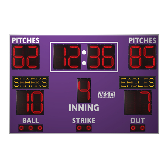
Summary of Contents for VARSITY Scoreboards 3355
- Page 1 INSTALLATION INSTRUCTIONS MODEL 3355 www.varsityscoreboards.com...
-
Page 2: Table Of Contents
Table of Contents Description Instructions for Reporting Shipping Damage Installation Overview Product Specifications Determining Location and Orientation Installing Mounting Poles or I-Beams Mounting the Scoreboard Running and Connecting the Control Cable Running and Connecting the Electric Service Testing the Installed System Warranty Activation... -
Page 3: Description
DESCRIPTION 3355 SCOREBOARD NOTE TO INSTALLERS: PLEASE RETURN THIS MANUAL TO THE INDIVIDUAL IN CHARGE OF THE SCOREBOARD UPON COMPLETION OF INSTALLATION. The scoreboard and all accompanying accessories have been carefully inspected and tested before leaving the factory. However, it is possible for damage to have occurred during shipping so we ask that you inspect all shipping containers upon arrival for damage and ensure that you have all of the parts listed below. -
Page 4: Installation Overview
INSTALLATION OVERVIEW This manual will walk you through the installation of the scoreboard. While care has been taken to consider the many scenarios for installation, some general information applies to all. Use this guide as closely as possible to ensure proper installation, as follows: 1. -
Page 5: Determining Location And Orientation
DETERMINING LOCATION AND ORIENTATION The scoreboard should be positioned so that the greatest number of spectators can easily view it. Also, consider the best orientation of the scoreboard should the system be used to score a daytime or afternoon game. The scoreboard should be positioned so that sunlight does not glare off of its face. In the U.S., placement on the South or West side of the field is recommended. -
Page 6: Mounting The Scoreboard
2. The poles/I-beams must be set into concrete footers. Make sure the poles are level and plumb and spaced on 4’ centers. The mounting faces of I-beams must be straight with each other. If the face of an I-beam is turned, shims will be needed to mount the scoreboard. The required dimensions for the footers vary depending on local building codes, soil &... - Page 7 2. Lift the scoreboard into place to the desired height, ensuring that the scoreboard is level. 3. Secure the scoreboard to the poles/beams using the mounting flanges attached to the scoreboard. The unit must be attached to each pole/beam on top and bottom. 4.
-
Page 9: Running And Connecting The Control Cable
RUNNING/CONNECTING THE CONTROL CABLE (For scoreboards with Wireless Remote Control, skip this step.) The control cable may be buried with or without conduit if the cable is direct burial-rated. Direct burial-rated cable in conduit is recommended for extended trouble free use. If the cable is not direct burial-rated cable, then it must be buried in a sealed, watertight conduit. -
Page 10: Running And Connecting The Electric Service
NOTE: If the colors of the wires in the control cable differ from those referenced on the label or shown in the following diagrams, refer to the notes you made when connecting the control cable to the junction box cover at the scorekeeper’s location. Ensure that each lead on the junction box cover is connected to the same color lead on the scoreboard terminal block, regardless of the color(s) of the wires in the control cable that connect them. - Page 11 Using the wireless system: Simply power on the LCD keyboard controller – the wireless transmitter is internally mounted. Testing the scoreboard system: Connect the appropriate end of the 12-volt DC wall transformer to the power receptacle on the back of the controller. Plug the transformer into a live, 120-volt outlet. If the optional battery pack was purchased with the keyboard, the transformer is also used to charge the battery.
-
Page 12: Warranty Activation
IMPORTANT! Warranty Activation/Installation & Completion Sign Off Sheet NOTE: This sheet must be completely filled out and returned/faxed (270) 753-3773 to Scoreboard Service Company before your warranty can be activated. Your Serial Number _______________________________________ Your Model Number _______________________________________ Date Purchased _______________________________________ Sales Agent _______________________________________...


Need help?
Do you have a question about the 3355 and is the answer not in the manual?
Questions and answers