
Subscribe to Our Youtube Channel
Related Manuals for schmersal ACC-AZM40-LEV-T-Test


Summary of Contents for schmersal ACC-AZM40-LEV-T-Test
-
Page 1: Table Of Contents
INSTRUÇÕES DE OPERAÇÃO E MONTAGEM ACC-AZM40-LEV-T-Test Table of Contents 1 About this document 1.1 Function 1.2 Target group of the operating instructions: authorised qualified personnel 1.3 Explanation of the symbols used 1.4 Appropriate use 1.5 General safety instructions 1.6 Warning about misuse 1.7 Exclusion of liability... -
Page 2: Target Group Of The Operating Instructions: Authorised Qualified Personnel
The user must observe the safety instructions in this operating instructions manual, the country specific installation standards as well as all prevailing safety regulations and accident prevention rules. Further technical information can be found in the Schmersal catalogues or in the online catalogue on the Internet: products.schmersal.com. -
Page 3: Warning About Misuse
There are no residual risks, provided that the safety instructions as well as the instructions regarding mounting, commissioning, operation and maintenance are observed. 1.6 Warning about misuse In case of inadequate or improper use or manipulations of the component, personal hazards or damage to machinery or plant components cannot be excluded. -
Page 4: Special Versions
2.2 Special versions For special versions, which are not listed in the ordering code, these specifications apply accordingly, provided that they correspond to the standard version. 2.3 Purpose The non-contact, electronic safety switchgear is designed for application in safety circuits and is used for monitoring the position and locking of movable safety guards. - Page 5 This device complies with the nerve stimulation limits (ISED SPR-002) when operated at a minimum distance of 100 mm. Changes or modifications not expressly approved by K.A. Schmersal GmbH & Co. KG could void the user's authority to operate the equipment.
-
Page 6: Mounting
This device complies with the nerve stimulation limits (ISED CNR-102) when operated at a minimum distance of 100 In the event of changes or modifications that have not been expressly approved by K.A. Schmersal GmbH & Co. KG, the user's authorisation to use the device may become ineffective. - Page 7 The M5 screws must be at least strength class 8.8 or, in stainless steel, strength class 80. The tightening torque of the M5 screws is 4 ... 6 Nm, the maximum tightening torque depends on the fastening screws used. The solenoid interlock is self-greasing. The grease on the locking bolt and in the actuator recess must not be removed. The accumulation of fine-grained dirt in the bolt area must be avoided.
- Page 8 The actuator must be permanently fitted to the safety guards and protected against displacement by suitable measures (tamperproof screws, gluing, drilling of the screw heads). Authorised actuator and interlock offset Tilt angle Rotating angle 8-23...
- Page 9 Actuating directions and switch distances The AZM40 can be operated within the following tolerance limits: X axis - 3 mm Y axis ± 1 mm Z axis ± 1.5 mm (actuator in centre position) Adjustment The two hexagon socket screws M4 can be used to adjust the actuator tongue in the X direction, using a hexagonal key wrench AF 2 mm.
-
Page 10: Manual Release
3.2 Manual release For installation and maintenance, the solenoid interlock can be unlocked in a de-energised condition. The solenoid interlock is unlocked by turning the auxiliary release anti-clockwise. The normal locking function is only restored after the manual release has been returned to its original position. Do not turn the manual release beyond the end stop. -
Page 11: Dimensions
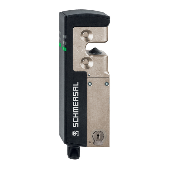
Connector plug M12, 8-pole LED indications Manual release (on both sides) Solenoid interlock ready for operation Solenoid interlock not ready for operation 3.3 Dimensions All measurements in mm. 11-23... - Page 12 Optional system components Retrofit kit emergency exit/emergency release The retrofit kit is used for subsequent functional expansion of the solenoid interlock. Designation Ordering code Emergency exit ACC-AZM40-LEV-T 103054265 Emergency release ACC-AZM40-LEV-N 103054268 Emergency exit with pushbutton - for 40 mm profiles ACC-AZM40-PT-T-40MM 103054271 - for profiles up to 170 mm...
-
Page 13: Electrical Connection
ACC-AZM40-LEV ACC-AZM40-PT Designation Ordering code Lockout device SZ40 103053182 Universal mounting plate, for 20, 30, 45, 50 MP-AZM40 103045324 and 60 mm profile systems, 2 pcs. Tamper-proof screws M5 x 25, flat head, 2 ACC-NRS-M5X25-FHS-2PCS 103045415 pcs. Tamper-proof screws M5 x 25, countersunk ACC-NRS-M5X25-CSS-2PCS 103045416... -
Page 14: Requirements For The Connected Safety-Monitoring Module
1 ms. The safety-monitoring module does not need to have a cross-wire short monitoring function, if necessary, the cross- wire short monitoring function must be disabled. Information for the selection of suitable safety-monitoring modules can be found in the Schmersal catalogues or in the online catalogue on the Internet: products.schmersal.com 4.3 Wiring configuration and connector accessories... -
Page 15: Wiring Examples
Pre-wired cables with socket (female) M12, 8-pole - 8 x 0.25 mm², IP67 / IP69 Cable length Ordering code 2.5 m 103011415 5.0 m 103007358 10.0 m 103007359 15.0 m 103011414 Connecting cables (PVC) with socket (female) M12, 8-pole - 8 x 0.21 mm², IP69 Cable length Ordering code 5.0 m... -
Page 16: Actuator Teaching / Actuator Detection
Wiring example: Series-wiring AZM40 The voltage is supplied at both safety inputs of the terminal safety component of the chain (considered from the safety-monitoring module). The safety outputs of the first safety component are wired to the safety-monitoring module. Y1 and Y2 = Safety outputs → Safety monitoring module 5 Actuator teaching / actuator detection Solenoid interlocks with standard coding are ready to use upon delivery. -
Page 17: Active Principle And Diagnostic Functions
that, an enabling inhibit will be active for ten minutes, thus providing for an increased protection against tampering. The green LED will flash until the expiration of the time of the enabling inhibit and the detection of the new actuator. In case of power failure during the lapse of time, the 10-minutes tampering protection time will restart. 6 Active principle and diagnostic functions 6.1 Magnet control The bistable interlock is released through operational setting of the IN signal (= 24 V). -
Page 18: Diagnostic Outputs
System condition No input signal at X1 and/or green yellow Safety guard open and a safety Flashes guard in the safety circuit (1 Hz) upstream is also open Safety guard closed and a Flashes Flashes safety guard in the safety (1 Hz) circuit upstream is open Safety guard locked and a... - Page 19 Sequence, locking signal is applied before the door is closed Disrupted process, door could not be locked or error Normal sequence, door was unlocked 19-23...
-
Page 20: Diagnostic Information
Sequence, door opened immediately after unlocking Disrupted process, door could not be unlocked Lock Unlock Locking time Door open Safety guard closed Safety guard not locked or fault Safety guard locked ... - Page 21 Table 1: Diagnostic information of the safety switchgear System Magnet Safety outputs Diagnostic condition control Y1, Y2 output (bistable) green yellow AZM40Z AZM40B Door open 24 V Door closed, 24 V Flashes 24 V 24 V not locked Door closed, Flashes Flashes...
-
Page 22: Set-Up And Maintenance
Table 2: Error messages / flash codes red diagnostic LED Flash codes (red) Designation Autonomous Error cause switch-off after 1 flash pulse Error (warning) at output Y1 30 min Fault in output test or voltage at output Y1, although the output is disabled. -
Page 23: Disassembly And Disposal
23-23 ACE Schmersal Eletroeletrônica Ind. Ltda, Av. Brasil, nº 815, Jardim Esplanada – CEP 18557-646 Boituva/SP Os dados e informações fornecidas foram cuidadosamente verificados. No entanto as imagens podem divergir do original. Informações técnicas adicionais podem ser encontradas no manual. Alterações técnicas e erros são possíveis.
Need help?
Do you have a question about the ACC-AZM40-LEV-T-Test and is the answer not in the manual?
Questions and answers