Advertisement
Quick Links
Advertisement

Related Manuals for Bachmann 4-6-0 LOCOMOTIVE with METAL GEARS


Summary of Contents for Bachmann 4-6-0 LOCOMOTIVE with METAL GEARS
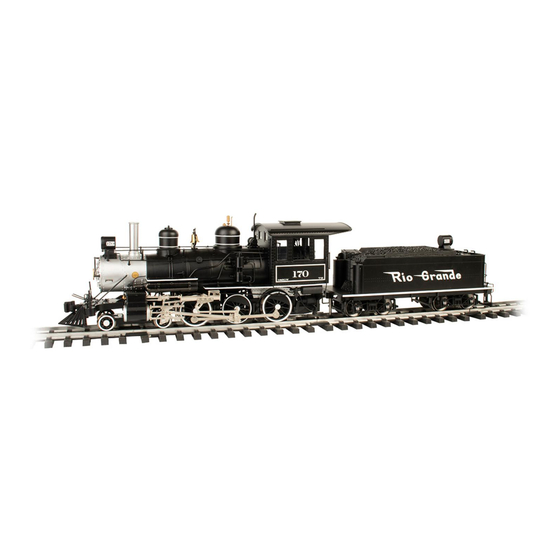
- Page 2 Bachmann 4-6-0 Features Your Bachmann Large Scale 4-6-0 is a precision model with many features and details making it an excellent addition to your railroad’s roster. The running gear and other parts of this locomotive will require lubrication before going into service for the first time on your railroad.
- Page 3 FEATURES of the 4-6-0 LOCOMOTIVE: This Large Scale model has many advanced features not offered by any other manufacturer of model trains, including: • advanced nonproprietary plug-and-play electronic printed circuit board to accommodate the control system of your • factory-installed speaker with wire pigtail to allow easy choice, including conventional DC power, NMRA/NEM installation of aftermarket sound system DCC, and/or RC operation...
-
Page 4: Lubrication Procedures
Failure to perform this initial lubrication may result in damage to your locomotive and poor operating performance. The product designers and engineers at Bachmann have designed your new locomotive so that lubrication can be performed in a few simple steps. There are, however, many moving parts and metal-to-metal connections, just like a real steam engine, so it is important to take your time and to lubricate all of them thoroughly. - Page 5 To begin, take your Bachmann E-Z Lube® Heavy Duty Gear Oil and place one or two drops on the motor shaft and gearbox. Angle the applicator through the rear lubrication port on the bottom of the chassis to reach beyond the drive axle and into the gearbox centered in front of the rear axle (Figure 2).
- Page 6 On the lead truck, add a drop or two of Heavy Gear Oil to each bearing surface where the wheel axles pass through the truck side frames (Figure 6). Be sure to remember the lead truck pivot point, where it attaches to the locomotive frame just in front of the lead driver (Figure 7).
- Page 7 When operating outdoors, under high temperatures, and other environmental conditions, there is a lot of friction, wear, and lubricant evaporation. Friction is metal’s worst enemy. Bachmann E-Z Lube® Conductive Contact Lubricant enhances electrical conductivity and will decrease the amp draw of your locomotive. Just put one drop on the electrical pickup point on each of the drive wheels (Figure 10) and on the end of each axle of the tender truck wheel sets where they enter the side frame (Figure 11).
-
Page 8: Valve Gear - Lubrication
CHANGING COUPLERS As shipped from the factory, the coupler is set to the low height used in Bachmann’s Big Haulers® line. If desired, you can raise the coupler to the NMRA (Spectrum®) height by simply removing the mounting screws and installing the coupler... - Page 9 out of the way. Next, remove the three screws holding the coupler shaft to the tender. Replace the low-height coupler and shaft with the high-height coupler and shaft (with the trip pin pointed down toward the truck) and reinstall the three screws (Figure 15).
- Page 10 Smoke Box Switch There is one switch behind the smoke box door (Figure 16) that controls the operation of the smoke generator. This switch has two positions: ON and OFF. In the ON position, the function above is controlled by the device installed in the plug-and-play socket. In the OFF position, the function will remain off, no matter how power is supplied to the locomotive.
- Page 11 4. Chuff Switch (small switch next to the polarity switch): The chuff switch is used to select either 2 or 4 chuffs per drive wheel revolution. PLUG-AND-PLAY SOCKET This Bachmann locomotive comes equipped with a nonproprietary plug-and-play electronics socket. This socket is designed to accommodate aftermarket plug-and- play products (contact your local hobby retailer for more information).
-
Page 12: Pin Definitions
PIN DEFINITIONS Each pin on the plug-and-play socket has a defined purpose and is labeled on the socket under the (DC) Jumper PC Board. Each pin is also connected to a solder pad for use with systems that do not support plug-and-play functionality (Figure 20). - Page 13 number number Purpose Purpose Solid Key Rail + Not used Rail + Firebox Flicker Motor + Not used Rear Light on Tender (if so equipped) Not used Smoke Unit Not used Locomotive Ground Not used Locomotive Positive Train Bus – Chuff Trigger 1 Train Bus + Front Locomotive Headlight...
- Page 14 TRACK-POWERED DC OPERATIONS To operate your locomotive via track power, leave the (DC) Jumper PC Board in place (Figure 21), make sure that the motor switch is “ON,” the pickup switch is in the “Track” position, and the track polarity switch is set for its correct position (normally the “Large Scale”...
- Page 15 revolution of the drivers. The switch is located in the front center of the tender under the polarity switch (small switch, Figure 18). To use the locomotive’s internal chuff for sound cards that do not plug into the socket, connect the sound board chuff connections to the main PC board solder pads, titled “Chuff Sensor”...
- Page 16 ADDING AFTERMARKET, TRACK-POWERED NMRA DCC OPERATION If your NMRA-compliant DCC decoder is designed for full plug-and play operation with the plug-and-play socket, remove the (DC) Jumper PC Board and replace it with your plug-and-play decoder. If your decoder is not designed for full plug-and-play operation, use the supplied Jumper PC Board with wires (Figure 24) and attach the wires to your decoder following the instructions that come with your decoder.
- Page 17 to allow the internal lighting and chuff system to function properly. An alternate installation approach if your Battery/RC system does not support plug-and-play operation is to connect the motor outputs of your RC system to the “BATT1” battery screw terminals (Figure 25). Should you wish to control the locomotive’s individual lighting and smoke functions, follow your specific manufacturer’s instructions for connecting these functions to the 4-6-0’s control system’s function inputs.
- Page 18 AND with the factory-supplied (DC) Jumper PC Board plugged in the plug-and-play socket. You can check out all of Bachmann’s other Large Scale products at your local hobby retailer or at shop.bachmanntrains.com. Contact our service department at: Service Department Bachmann Industries, Inc.
Need help?
Do you have a question about the 4-6-0 LOCOMOTIVE with METAL GEARS and is the answer not in the manual?
Questions and answers