Table of Contents
Advertisement
We advise you to read this manual carefully, which contains all the instructions for
maintaining the appliance's aesthetic and functional qualities.
For further information on the product: www.smeg.com
Contents
4
4
4
4
4
5
5
5
6
6
7
7
9
9
12
12
13
13
14
15
16
16
18
19
23
23
23
24
25
25
27
28
30
31
31
34
38
39
3
Advertisement
Table of Contents

Related Manuals for Smeg TR4110BL


Summary of Contents for Smeg TR4110BL
-
Page 1: Table Of Contents
5.2 Adaptation to different types of gas 5.3 Electrical connection 5.4 Positioning We advise you to read this manual carefully, which contains all the instructions for maintaining the appliance's aesthetic and functional qualities. For further information on the product: www.smeg.com... -
Page 2: Instructions
Instructions 1 Instructions 1.2 This user manual This user manual is an integral part of the 1.1 How to read the user manual appliance and must therefore be kept in its This user manual uses the following reading entirety and in an accessible place for the whole working life of the appliance. -
Page 3: Manufacturer Liability
(cutlery or utensils) into the slots in the compartment. appliance. • Do not rest any weight or sit on the open Power voltage door of the appliance. Danger of electrocution • Take care that no objects are stuck in the doors. -
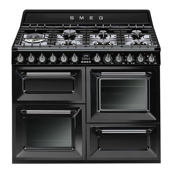
Page 4: Description
Description 2 Description 2.1 General description 1 Skirt 6 Door 2 Cooking hob 7 Fan 3 Control panel 8 Storage compartment 4 Oven light Shelf for racks/trays support frames 5 Seal... -
Page 5: Cooking Hob
Ultra rapid burner knob (1) Press and turn the knob anti-clockwise to the symbol to light the burner external Useful for lighting and adjusting the ultra crown. Turn the knob to the zone between rapid burner. the maximum and minimum setting Press and turn the knob anti-clockwise to to adjust the flame. - Page 6 Useful for lighting and adjust the hob burners. The indicator light comes on to indicate that the oven is heating up. It turns off as soon as Press and turn the knobs anti-clockwise to it reaches the set temperature. It flashes the value to light the relative burners.
-
Page 7: Other Parts
Useful for holding cooking containers. Tray rack Internal light The internal light of the ovens comes on when any function is selected. To be placed over the top of the oven tray; for cooking foods which may drip. - Page 8 Deep tray Useful when using a wok. Teppanyaki plate Useful for collecting fat from foods placed on the rack above and for cooking pies, pizzas and baked desserts. Useful for cooking meat, fish and vegetables directly on the plate without...
- Page 9 Scraper Useful for cleaning the Teppanyaki plate. Do not use on other surfaces. The accessories intended to come into contact with food are made of materials that comply with the provisions of current legislation. Original and optional accessories can be requested to Authorised Assistance Centres.
-
Page 10: Use
• Do not use plastic kitchenware or • If you need to move food or at the end containers when cooking food. of cooking, open the door 5 cm for a • Do not put sealed tins or containers in few seconds, let the steam come out, the oven. -
Page 11: First Use
• The mechanical safety locks that prevent the bottom of the cooking compartment. the rack from being taken out • Do not use the open door to rest pans or accidentally have to face downwards trays on the internal glass pane. -
Page 12: Using The Hob
3.4 Using the hob Tray rack All the appliance's control and monitoring The tray rack has to be inserted into the tray. devices are located together on the front In this way fat can be collected separately panel. The burner controlled by each knob from the food which is being cooked. -
Page 13: Teppanyaki Plate
Risk of damage to surfaces that the flame-spreader crowns are correctly positioned in their housings with • The plate must not be used for more than their respective burner caps. Make sure that 60 minutes. the holes in the flame-spreader crowns are aligned with the igniters and thermocouples •... -
Page 14: Using The Storage Compartment
3.6 Using the storage compartment The storage compartment is at the bottom right of the cooker. It can be used to store cookware or metallic objects necessary when using the appliance. Multifunction oven doors do not block laterally when opening and they might close. - Page 15 Perfect for all types of roasts, therefore need a little more heat. bread and cakes and in any case Perfect for any type of food.
-
Page 16: Cooking Advice
• Use a meat thermometer when roasting meat, or simply press on the roast with a spoon. If it is hard, it is ready; if not, it needs another few minutes cooking. -
Page 17: Programming Clock
• Reduce any opening of the door to a • To check whether the dessert is cooked minimum to avoid heat dispersal. right through: at the end of the cooking time, put a toothpick into the highest point •... - Page 18 Setting the time 4. At the end of cooking the heating elements will be deactivated. On the On the first use, or after a power failure, the display, symbol turns off, symbol digits will be flashing on the flashes and the buzzer sounds.
- Page 19 6. To turn off the buzzer just press any key of the programmer clock. Adjusting the buzzer volume 7. Press keys at the same time to reset the programmer clock.
-
Page 20: Cooking Information Table
160 - 170 50 - 60 Brioches Circular 25 - 30 Short pastry biscuits Fan-assisted static 160 - 170 16 - 20 The times indicated in the table do not include preheating times and are provided as a guide only. -
Page 21: Cleaning And Maintenance
• Do not use steam jets for cleaning the Do not allow residues of sugary foods (such appliance. as jam) to set inside the oven. If left to set for • Do not use cleaning products containing too long, they might damage the enamel chlorine, ammonia or bleach on steel lining of the oven. -
Page 22: Removing The Door Of The Auxiliary Oven
1. Open the door completely and insert two toothpick or a needle. pins into the holes on the hinges indicated in the figure. 2. Grasp the door on both sides with both hands, lift it forming an angle of around Teppanyaki plate 30° and remove it. -
Page 23: Cleaning The Door Glazing
Cleaning and maintenance and once it is in place remove the pins detach from their housings in the oven from the holes in the hinges. door. 4.4 Cleaning the door glazing The glass in the door should always be kept Improper use thoroughly clean. - Page 24 (1). 2. Then, pull the front part upwards (2). In this way, the 4 pins attached to the glass detach from their housings in the oven door.
-
Page 25: Cleaning The Inside Of The Oven
Take out all removable parts. and neutral detergent. Clean the oven racks with warm water and 5. Replace the panels in the reverse order in non-abrasive detergent. Carefully rinse and which they were removed. dry the damp parts. -
Page 26: Vapor Clean: Assisted Oven Cleaning
The dirt residues are from its groove A, then slide it out of the softened by the heat and water seats B at the back. - Page 27 2. Set a cooking time of 18 minutes using the timer knob. 3. At the end of the cooking time, the timer will switch the oven heating elements off and the buzzer will start to sound. End of the Vapor Clean cycle •...
-
Page 28: Extraordinary Maintenance
To permit thorough cleaning of the oven, the Replacing the internal light bulb door seal can be removed. There are hooks on all four sides to attach it to the 1. Completely remove all accessories from edge of the oven. Pull the edges of the seal inside the oven. -
Page 29: Installation
• the hose is fixed to the hose connection with safety clamps; Gas leak • no part of the hose is in contact with hot Danger of explosion walls (max. 50 °C); • the hose is not under traction or tension •... - Page 30 Installation 5 that is compliant with the standard in Connection with a flexible steel hose with bayonet fitting force. Carry out the connection to the gas mains using a flexible steel hose with bayonet fitting compliant with B.S. 669. Apply...
- Page 31 Carefully screw the hose connector 3 to the room itself. The air vents, protected by appliance’s gas connector 1 (½”...
-
Page 32: Adaptation To Different Types Of Gas
The appliance is pre-set for natural gas G20 (2H) at a pressure of 20 mbar. In case of operation with other types of gas, the burner nozzles must be changed and the minimum flame adjusted on the gas taps. - Page 33 Adjusting the minimum setting for natural Adjusting the minimum setting for LPG or city gas Tighten the screw located at the side of the Light the burner and turn it to the minimum tap rod clockwise all the way. position. Extract the gas tap knob and turn...
- Page 34 Installation Gas types and Countries Gas types GB-IE FR-BE 1 Natural Gas G20 20 mbar • • • • • • • • • G20/25 20/25 mbar • 2 Natural Gas G25 • 25 mbar 3 Natural Gas G25 20 mbar •...
- Page 35 Installation Burner and nozzle characteristics tables 1 Natural Gas G20 UR2 int. Rated heating capacity (kW) Nozzle diameter (1/100 mm) 97+97 Pre-chamber (printed on nozzle) Reduced capacity (W) 1600 2 Natural Gas G25 UR2 int. Rated heating capacity (kW) Nozzle diameter (1/100 mm)
-
Page 36: Electrical Connection
• 380-415 V 2N~ • Disconnect the main power supply. • Do not pull the cable to remove the plug. • Use H05V2V2-F cables withstanding a temperature of at least 90°C. use a 4 x 4 mm² four-core cable. -
Page 37: Positioning
Connection with plug and socket Pressure on the open door Make sure that the plug and socket are of Risk of damages to the appliance the same type. Avoid use of adapters and shunts as these •... - Page 38 Installation Depending on the type of installation, this appliance belongs to classes: C - Class 2 subclass 1 A - Class 1 (Built-in appliance) (Free-standing appliance) The appliance must be installed by a qualified technician and according to the regulations in force.
- Page 39 1. Loosen the 6 screws on the back of the top (A) and unscrew the 2 screws (B) on 1. Place the skirting in the front bottom part the side part of the skirt.
- Page 40 Installation 3. Use the same height on the wall to drill Wall mounting brackets (where present) the holes for fastening the brackets. The Heavy appliance distance between the centres of the Risk of damages to the appliance holes is given in the diagram above.
Need help?
Do you have a question about the TR4110BL and is the answer not in the manual?
Questions and answers