Table of Contents
Advertisement
Quick Links
TRANSLATION OF THE ORIGINAL INSTRUCTIONS
We advise you to read this manual carefully, as it contains all the instructions for maintaining
the appliance's aesthetic and functional qualities.
For further information on the product: www.smeg.com
Table of contents
54
54
59
59
59
59
59
60
61
61
62
63
64
65
66
67
68
71
76
76
78
80
84
85
86
88
89
91
94
94
100
102
53
Advertisement
Table of Contents

Related Manuals for Smeg Victoria TR90IGR


Summary of Contents for Smeg Victoria TR90IGR
-
Page 1: Table Of Contents
5.2 Electrical connection 5.3 Instructions for the installer TRANSLATION OF THE ORIGINAL INSTRUCTIONS We advise you to read this manual carefully, as it contains all the instructions for maintaining the appliance’s aesthetic and functional qualities. For further information on the product: www.smeg.com... -
Page 2: Instructions
Instructions 1 Instructions • Keep children under the age of 8 away from the appliance when it 1.1 General safety instructions is in use. • Cleaning and maintenance must Risk of personal injury not be carried out by • During use the appliance and its unsupervised children. - Page 3 Instructions • Do not insert pointed metal • Switch off the appliance objects (cutlery or utensils) into the immediately after use. slots in the appliance. • DO NOT MODIFY THIS • Do not pour water directly on very APPLIANCE. hot trays. •...
- Page 4 Instructions Risk of damaging the appliance • DO NOT USE THE APPLIANCE TO HEAT ROOMS FOR ANY • Do not use abrasive or corrosive REASON. detergents (e.g. scouring • Do not spray any spray products powders, stain removers and near the oven. metallic sponges) on glass parts.
- Page 5 Instructions • If any liquid does boil over or spill, • Do not use steam jets to clean the remove the excess from the hob. appliance. • Take care not to spill acid • Do not use rough or abrasive substances such as lemon juice or materials or sharp metal scrapers.
- Page 6 Instructions Installation For this appliance • THIS APPLIANCE MUST NOT BE • After use, turn off the plates. INSTALLED IN A BOAT OR Never rely solely on the CARAVAN. cookware detector. • The appliance must not be • Supervise children carefully as installed on a pedestal.
-
Page 7: Manufacturer Liability
Instructions 1.2 Manufacturer liability 1.5 This user manual The manufacturer declines all liability This user manual is an integral part of for damage to persons or property the appliance and must therefore be caused by: kept in its entirety and within the user's reach for the whole working •... -
Page 8: How To Read The User Manual
Instructions • Deliver the appliance to the 1.7 How to read the user manual appropriate recycling centre for This user manual uses the following reading electrical and electronic conventions: equipment waste, or return it to Instructions the retailer when purchasing an General information on this user equivalent product, on a one for manual, on safety and final... -
Page 9: Description
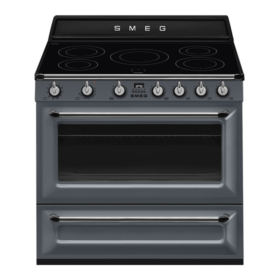
Description 2 Description 2.1 General Description 1 Upstand 6 Door 2 Cooking hob 7 Fan 3 Control panel 8 Storage compartment 4 Light bulb Rack/tray support frame shelf 5 Seal... -
Page 10: Cooking Hob
Description 2.2 Cooking hob Power consumption Outer diameter Max. power absorbed Zone in Booster function (mm) (W)* (W)* 1300 1400 2300 3000 2300 3000 Power levels are approximate and can vary according to the pan used or the settings made. •... -
Page 11: Control Panel
Description 2.3 Control panel 1 Function knob 4 Hob cooking zone knobs The oven's various functions are suitable for Useful for controlling the cooking zones of different cooking methods. After selecting the induction hob. the required function, set the cooking Turn the knobs clockwise to adjust the temperature using the temperature knob. -
Page 12: Other Parts
Description 2.4 Other parts Cooling fan The fan cools the ovens and comes into Shelves operation during cooking. The appliance features shelves to position The fan causes a steady outflow of air that trays and racks at different heights. The exits from the rear of the appliance and insertion heights are indicated from the which may continue for a brief period of... -
Page 13: Available Accessories
Description 2.5 Available accessories Rotisserie Rack Used for supporting containers with food Useful for cooking chicken and all foods during cooking. that require uniform cooking over their entire Tray rack surface. Not all accessories are available on some models. The accessories intended to come into contact with food are made of materials that comply with the provisions of current legislation. -
Page 14: Use
3 Use Improper use Risk of damage to surfaces Instructions High temperature inside the oven • Do not cover the bottom of the oven during use cavity with aluminium or tin foil sheets. Danger of burns • If you wish to use greaseproof paper, place it so that it will not interfere with the •... -
Page 15: To Save Energy
Glass ceramic hob High temperature inside the storage compartment during use 5. Place a pan full of water on each of the front cooking zones and switch them on Danger of fire or explosion to the maximum power setting for at •... -
Page 16: Using The Accessories
• Remove all trays and racks which are not Racks and trays required during cooking. Racks and trays have to be inserted into the • Stop cooking a few minutes before the side guides until they come to a complete time normally used. - Page 17 Rotisserie 3. Prepare the rotisserie rod with the food using the rotisserie rod provided. The 1. Insert the 4 supplied bushings in the clip forks can be tightened using the 4 corner holes of the deep tray and fastening screws. screw them onto the ring nuts with a suitable tool (such as a screwdriver).
- Page 18 5. Place the tray on the first runner (see 7. To activate the rotisserie, turn the “General Description”). function knob to the position and 6. Insert the tip of the rod in the rotisserie set the cooking temperature using the motor housing on the left of the rear temperature knob.
-
Page 19: Using The Hob
3.3 Using the hob To see whether the pan is suitable, bring a magnet close to the bottom: if it is attracted, On first connection to the electrical the pan is suitable for induction cooking. If mains, an automatic check will be you do not have a magnet, you can put a carried out that will switch on all small amount of water in the pan, place it... - Page 20 Cookware recognition Limiting the cooking duration The hob has an automatic device which When there is no saucepan on a cooking zone or if the saucepan is too small, no limits the duration of use. energy will be transmitted and the symbol If the cooking zone settings are not changed, the maximum duration of will appear on the display.
- Page 21 Advice on energy-saving Power levels • The diameter of the base of the pan must The power in the cooking zone can be correspond to the diameter of the adjusted to various levels. The table shows cooking zone. the levels suitable for various types of cooking.
- Page 22 Heating accelerator Keep warm Each cooking zone is equipped The Keep warm function allows with a heating accelerator that you to keep cooked food hot. allows the maximum power to be delivered for a time that is To activate the Keep Warm function: proportional to the selected •...
- Page 23 Power control Control lock The hob is fitted with a power control The controls lock is a device that module that optimises/limits consumption. If protects the appliance from the overall set power level exceeds the accidental or inappropriate use. maximum limit permitted, the electronic circuit board will automatically manage the 1.
-
Page 24: Using The Storage Compartment
3.4 Using the storage compartment Functions list There is a storage compartment located at Static the bottom of the cooker; this can be used As the heat comes from above and to store pans or metal objects required for below at the same time, this system its use. - Page 25 Grill Fan with round heating element The heat coming from the grill The combination of the fan and the element gives perfect grilling results round heating element above all for thin and medium (incorporated in the rear of the thickness meat and, in combination oven) allows you to cook different with the rotisserie (where fitted), foods on several levels, as long as...
-
Page 26: Cooking Advice
3.6 Cooking advice General advice This function is particularly suitable • Use a fan assisted function to achieve for cooking on a single shelf with consistent cooking at several levels. low energy consumption. • It is not possible to shorten cooking times Ideal for cooking meat, fish and by increasing the temperature (the food vegetables. - Page 27 • With the Grill function, we recommend Advice for defrosting and proving that you turn the temperature knob to the • Place frozen foods without their maximum value near the symbol packaging in a lidless container on the first shelf of the oven. optimise cooking.
-
Page 28: Programmer Clock
3.7 Programmer clock Setting the time If the time is not set, the oven will not switch on. On the first use, or after a power failure, the digits will be flashing on the appliance’s display. 1. Press the keys at the same time. - Page 29 Timed cooking 6. Press the keys at the same time to reset the programmer clock. Timed cooking is the function which allows a cooking operation to be started and then ended after It is not possible to set a cooking a specific length of time set by the time of more than 10 hours.
- Page 30 Minute minder timer 3. Use the key to set the required minutes. The minute minder timer does not stop the cooking operation but 4. Wait approx. 5 seconds without pressing rather informs the user when the set any key in order for the function to time has run out.
- Page 31 Cooking information table Weight Temp. Food Function Shelf Time (minutes) (kg) (°C) Lasagne 3 - 4 Static 220 - 230 45 - 50 Pasta bake 3 - 4 Static 220 - 230 45 - 50 Roasted veal Circulaire/Fan assisted 180 - 190 90 - 100 Pork loin Circulaire/Fan assisted...
-
Page 32: Cleaning And Maintenance
4 Cleaning and maintenance Cleaning the surfaces To keep the surfaces in good condition, Instructions they should be cleaned regularly after use. Let them cool first. Improper use Risk of damage to surfaces Ordinary daily cleaning Always use specific products only that do •... -
Page 33: Cleaning The Hob
Cleaning and maintenance 4.1 Cleaning the hob Weekly cleaning Clean and maintain the hob once a week Cleaning the glass ceramic hob using an ordinary glass ceramic cleaning Light coloured marks from pans with product. Always follow the manufacturer’s aluminium bases can be easily cleaned off instructions. -
Page 34: Cleaning The Door
Cleaning and maintenance 4.2 Cleaning the door 3. To reassemble the door, put the hinges in the relevant slots in the oven, making sure Removing the door that grooved sections A are resting For easier cleaning it is recommended to completely in the slots. - Page 35 Cleaning and maintenance Removing the internal glass panes 5. Remove the intermediate glass pane by lifting it upwards. For easier cleaning the internal glass panes of the door can be removed. 1. Open the door. 2. Position the locking hooks in the hinge holes to prevent accidental closing of the door.
-
Page 36: Cleaning The Oven Cavity
Cleaning and maintenance 4.3 Cleaning the oven cavity Removing racks/trays support frames In order to keep your oven in the best Removing the rack/tray support frames possible condition, clean it regularly after enables the sides to be cleaned more letting it cool down. easily. -
Page 37: Vapor Clean
Cleaning and maintenance Cleaning the top section 4.4 Vapor Clean The oven cavity is fitted with a tilting heating Vapor Clean is an assisted element which facilitates cleaning the top cleaning procedure which part (roof) of the oven. facilitates the removal of dirt. This 1. - Page 38 Cleaning and maintenance • Pour approximately 40 cc of water into Vapor Clean setting the tray. Make sure it does not overflow 1. Turn the function knob to the symbol out of the cavity. and the temperature knob to the symbol 2.
-
Page 39: Extraordinary Maintenance
Cleaning and maintenance End of the Vapor Clean cycle 4.5 Extraordinary maintenance 4. Open the door and wipe away the less Installing and removing the seal stubborn dirt with a microfibre cloth. To remove the seal: 5. Use an anti-scratch sponge with brass •... - Page 40 Cleaning and maintenance 4. Slide out and remove the light bulb. Replacing the internal light bulb Live parts Danger of electrocution • Unplug the appliance from the mains. The oven is fitted with a 40W light bulb. 1. Completely remove all accessories Do not touch the halogen light from inside the oven.
- Page 41 Cleaning and maintenance What to do if... The hob smokes: • The hob is dirty, clean it once cooking The appliance is not working properly: has finished. • The switch is defective: check the fuse The cookware in use are making a noise. box to see whether the switch is in working order.
-
Page 42: Installation
Cleaning and maintenance 5 Installation Any wall units positioned above the worktop of the appliance must be at a 5.1 Positioning minimum distance of at least Y mm. If a hood is installed above the hob, refer to the Heavy appliance hood instruction manual to ensure the Crushing hazard correct clearance is left. - Page 43 Installation Appliance overall dimensions 900 mm 600 mm B - Class 2 subclass 1 500 mm (Built-in appliance) 900 mm 750 mm 450 mm 900 mm Minimum distance from side walls or other flammable material. Minimum cabinet width (=A). C - Class 2 subclass 1 (Built-in appliance) The appliance must be installed by a qualified technician and...
- Page 44 Installation Appliance dimensions Positioning and levelling Position of gas and electrical connections. Heavy appliance Risk of damage to the appliance • Insert the front feet first and then the rear ones. The appliance must sit level on the floor to ensure stability.
- Page 45 Installation Assembling the upstand Mounting the toe skirt The upstand provided is an The toe skirt provided is an integral integral part of the product; it must part of the product; it must be be fastened to the appliance prior fastened to the appliance prior to to installation.
- Page 46 Installation 3. Assemble the fastening bracket. Fastening to the wall The anti-tip devices must be installed in order to prevent the appliance from tipping over. 1. Screw the wall fastening plate to the rear of the appliance. 4. Align the base of the hook on the fastening bracket with the base of the slot on the wall fastening plate.
- Page 47 Installation 5. Align the base of the fastening bracket 7. Move the bracket onto the wall and with the ground and tighten the screws mark the position of the holes to be to fix the measurements. drilled in the wall. 6.
-
Page 48: Electrical Connection
Installation 5.2 Electrical connection The appliance can work in the following modes: Power voltage • 220-240 V 2~ Danger of electrocution • Have the electrical connection performed by authorised technicians. • Use personal protective equipment. 3 x 10 mm² three-core cable. •... - Page 49 Installation Fixed connection The aforementioned power cables are sized taking into account the Fit the power line with an omnipolar circuit coincidence factor (in compliance breaker in compliance with installation with standard EN 60335-2-6). regulations. The circuit breaker should be located near Replacement U-bolt the appliance and in an easily reachable position.
-
Page 50: Instructions For The Installer
Installation Access to the terminal board To connect the power supply cable, access Loosen the cable fastener screw to the terminal board on the rear cover: before installing the power supply 1. Remove the screws securing the lid to cable. the rear cover.
Need help?
Do you have a question about the Victoria TR90IGR and is the answer not in the manual?
Questions and answers