Rupert Neve Designs 5088 Operation Manual
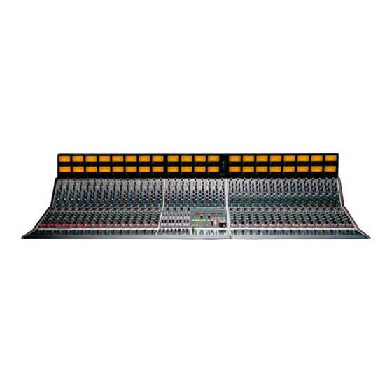
Fully discrete analog mixer
Hide thumbs
Also See for 5088:
- Operation manual (31 pages) ,
- Operation manual (36 pages) ,
- Operation manual (45 pages)

Related Manuals for Rupert Neve Designs 5088


Summary of Contents for Rupert Neve Designs 5088
- Page 1 508 8 5088 5088 Fully Discrete Analogue Mixer Fully Discrete Analog Mixer Operations Manual Operations Manual Operations Manual Operations Manual...
- Page 2 CAUTION: Changes or modifications to this device not expressly 11. Only use attachments/accessories specified by the manufacturer. approved by Rupert Neve Designs LLC, could void the user's authority to 12. Use only with a cart, stand, tripod, bracket, or PORTABLE CART operate the equipment under FCC rules.
-
Page 3: Table Of Contents
Unpacking Installing Modules Guarding Against Interference Connecting Audio Connecting the Power Supply Studio Configuration Suggestions Dimensions 5088 Console Block Diagram Cleaning and Service Instructions Channel Module Channel Module Block Diagram Group Module Group Module Block Diagram Master Section Master Section Block Diagram... -
Page 5: Introduction
DO NOT operate the 5088 near any water sources or in areas with high indoor air pollution (smoke, dust, etc.) DO NOT place any beverages on or around the 5088 console. -
Page 6: Unpacking
5088: Operations Manual DO NOT setup the 5088 Console or its Power Supplies in an unventilated or tightly enclosed space. DO NOT block any of the chassis ventilation holes. The 5088’s class-A discrete circuits generate heat during operation and the ventilation holes allow the internal console fans to properly dissipate the heat. -
Page 7: Installing Modules
5088: Operations Manual Once the 5088 is out of the crate, you may begin removing the boxes from the bottom section of the crate. BE CAREFUL to install the 541 CHANNEL and 561 GROUP Modules in the correct slots. CHANNEL and GROUP modules are NOT interchangeable. -
Page 8: Guarding Against Interference
5088 Console’s I/O to a patch bay. Installing a patch bay will protect the 5088’s rear panel I/O from unnecessary wear and will make signal routing more convenient. - Page 9 5088: Operations Manual Back Panels Channel I/O NPUT NPUT NPUT NPUT NPUT NPUT NPUT NPUT NPUT NPUT NPUT NPUT NPUT NPUT NPUT NPUT NPUT NPUT NPUT NPUT NPUT NPUT NPUT NPUT IRECT IRECT IRECT IRECT IRECT IRECT IRECT IRECT UTPUT...
-
Page 10: Connecting The Power Supply
AD Converter inputs. Route each DA Converter output to a corresponding tape input on the 5088 (if latency is acceptably low), and create stereo and cue mixes with the 5088’s 541 Channel and 561 Group routing controls for recording or mixing. -
Page 11: Dimensions
5088: Operations Manual 5088 Console Dimensions 5088 Console Weights “Super 8” Main Chassis “Super 8” Main Chassis 16 Channel Console (No Penthouse or Meterbridge) Width: 76 cm / 29.9 in Width: 76 cm / 29.9 in Unloaded Frame Weight: 127 lbs. - Page 12 5088: Operations Manual...
- Page 13 5088: Operations Manual...
- Page 14 5088: Operations Manual...
- Page 15 5088: Operations Manual...
- Page 16 5088: Operations Manual...
- Page 17 Shipping To remove a 541 Channel or 561 Group module for servicing, power off the 5088, unscrew the thumbscrews at the top and Instructions bottom of the module and carefully slide the module out of the slot by pulling upwards on the thumbscrews.
- Page 18 5088: Operations Manual 541 Channel Module series TAPE Input Select Input Trim LINE BUSS Phase Reverse TRIM GROUPS STEREO Group Send Select Aux 7/8 Level LEVEL 8 Pre/Post Select LEVEL 7 Aux 7/8 On Aux 5/6 On LEVEL 6 PAN 5/6...
-
Page 19: Channel Module
5088: Operations Manual The push-buttons at the top of each 541 Channel select be- Channel Module tween transformer-coupled LINE, BUSS or TAPE inputs. The BUSS input is not a line input, and should only be used with BUSS outputs from Portico modules. - Page 20 Aux 5/6 as well as the Direct Output. Jumpers Before removing Channel modules to change jumper posi- tions, power off the 5088. Grab the jumpers using your fingers or a small set of needle-nose pliers. Aux 5/6: Pre-Fader/Post Fader...
- Page 21 5088: Operations Manual Post-fader / Post-mute (default) Pre-fader / Pre-mute Pre-fader / Post-mute...
- Page 22 5088: Operations Manual...
- Page 23 5088: Operations Manual...
- Page 24 5088: Operations Manual 551 Stereo Channel Module series METER Right Input Trim Left Input Trim TRIM Phase Reverse TRIM GROUPS STEREO Group Send Select Aux 5/6 On Aux 5/6 Level and 5/6 Balance ∞ Aux 5 Level LEVEL 6 BAL 5/6...
- Page 25 5088: Operations Manual At the top of the stereo channel module, there are push-but- Stereo Channel tons that allow the user to select between metering the left Module and right inputs, as well as a phase reverse. Each 551 Channel features: A Left and Right input TRIM control with - 10dB/+10dB ful- •...
- Page 26 5088: Operations Manual...
- Page 27 5088: Operations Manual...
-
Page 28: 561 Group Module
5088: Operations Manual 561 Group Module Stereo Effects Input Trim Stereo Effects Group Sends Stereo Effects Solo Send Stereo Effects Mute SOLO Aux Master Level Aux Master Solo Send SOLO SOLO Aux Master Engage Group Master Insert Group Pan Select... - Page 29 Stereo Buss. SOLO and MUTE illuminated latching buttons. Each Stereo Effects Return consists of two transformer- coupled line inputs which connect to TRS jacks on the 5088’s Back Panel I/O. The 561 Group includes a pair of transformer-coupled Auxiliary Master Outputs that are accessible on the 5088’s Back Panel I/O via XLR jacks.
- Page 30 5088: Operations Manual Group Module Direct Output: Pre-Fader/Post Fader Group Module Jumpers By default, the 561 Group Direct Outputs are set to Post-Fad- er, Post-Mute. This can be changed via internal jumpers (J1, J2, J4, J5, J10 and J11). Before attempting this change, please contact our support staff at the following email address: service@rupertneve.com...
- Page 31 5088: Operations Manual Group Module Aux Buss Selector The Aux Buss that each 561 Group module receives is de- termined by the position of jumpers J8 and J9. In the photo below, Group Module 1/2 has internal jumpers J8 and J9 set to receive Aux Buss 1 and 2.
- Page 32 5088: Operations Manual...
- Page 33 5088: Operations Manual...
-
Page 34: Master Section
5088: Operations Manual Master Section Rupert Neve Designs 5088 F u l l y D i s c r e t e A n a l o g u e M i x e r LEFT RIGHT TALKBACK OSCILLATOR 100 Hz... - Page 35 GROUPS. If additional external Talkback signal routing is required, the TB TO OSC OUT button routes the Talkback signal to the male XLR on the 5088’s Back Panel I/O labeled OSCILLATOR. All five of these Talkback routing options can be used individually or simultaneously.
- Page 36 Speaker Select Section Three buttons, MON A, MON B, and MON C allow the transformer-coupled Monitor outputs to be assigned to one of 3 sets of stereo male XLR loudspeaker outputs on the 5088’s Back Panel I/O. Monitor Section The Monitor source can be selected via the STEREO MIX and EXT 1, EXT 2, and EXT 3 buttons.
- Page 37 Jumper J3 is set by default to a low gain Talkback setting, intended for use with a condenser microphone. To change these jumper settings, first power down the 5088 Console. Loosen the thumbscrews on the 561 Group modules 5/6 and 7/8. Removing these two 561 Group modules will provide enough space to change the jumper settings without removing the Master Section.
- Page 38 5088: Operations Manual...
- Page 39 5088: Operations Manual...
- Page 40 5088: Operations Manual 5051 EQ/Compressor 5051 EQ/Compressor NDUCTOR EQ Line Input Select LINE 1 LINE 2 HF Shelf Gain EQ In EQ IN HF Shelf Frequency Select 1.5K Mid Frequency Select High Frequency Peak HI PEAK MID FREQ Mid Hi-Q Select...
- Page 41 5088: Operations Manual 5051 Features The 5051 EQ/Compressor requires its own standalone power supply to operate. The power supply features proprietary 4-pin polarized outputs at +24 and -24V DC, and will power up to twenty-five 5051 modules. LINE 1 / LINE 2 Allows you to have two sources pre-patched into the 5051.
- Page 42 5088: Operations Manual MID FREQ The MID FREQ rotary switch has 6 positions to select the center frequency of the mid band EQ stage. This circuit utilizes an inductor and capacitors to shape the EQ curve, the same way as Rupert Neve’s console designs of the 70’s. The frequencies chosen are 200 Hz, 350 Hz, 700 Hz, 1.5kHz, 3 kHz and 6 kHz.
- Page 43 5088: Operations Manual Engages an 18 dB per octave Butterworth high pass filter to remove unwanted low frequency sounds. This button actually allows two different corner frequencies. The first press selects a 60 Hz filter denoted by the light illuminating blue.
- Page 44 5088: Operations Manual S/C HPF Engages a 250Hz, 12dB per octave high pass filter to prevent low frequency material from excessively controlling the compressor. With mixes or wide spectrum sounds, there is often significant amounts of low frequency energy that can...
- Page 45 5088: Operations Manual LINK Allows multiple 5051 modules to be linked together such that at any given time, the 5051 with the highest control voltage will control the compression of all the linked units. To create a stereo pair, first adjust the two modules so that they have identical compression and EQ setting.
- Page 46 5088: Operations Manual COMP IN Engages the compressor, and is indicated by a green button. Other than simply engaging the compressor, engineers often toggle this button to aid adjusting the make-up gain for similar average levels. The comp in button is also used to compare the untreated signal to the compressed signal to verify a positive change is being made.
- Page 47 5088: Operations Manual S/C INSERT SEND A 1/4” unbalanced phone jack used to send the signal to an external device, primarily EQ, to create a key signal (it can be any old EQ or device since the audio isn’t effected). For...
- Page 48 5088: Operations Manual LINE 1 XLR female transformer balanced floating input associated with the LINE 1 position of the front panel input switch. Pin 2 high, 10 k Ohm input impedance. LINE 2 XLR female transformer balanced floating input associated with the LINE 2 position of the front panel input switch.
- Page 49 5088: Operations Manual LINE IN (All measurements typical) 5051 Specifications Frequency Response Main Output 2.5 Hz to 125 kHz -3dB Noise (BW 22Hz - 22kHz) Main Output Better than –102 dBu Maximum Input Level 20 Hz to 20 kHz +25 dBu...
- Page 50 5088: Operations Manual COMPRESSOR (All measurements typical) Noise (BW 22Hz - 22kHz) Main Output Better than –92 dBu THD+N% (BW 10 Hz - 80kHz) @ +20dBu 20Hz Better than 0.14% 1kHz Better than 0.02% 20kHz Better than 0.07% Threshold -30dBu to +20dBu Ratio 1.1:1 to 40:1...
- Page 51 5088: Operations Manual...
- Page 52 5088: Operations Manual 5052 Mic Pre/EQ 5052 Mic Pre/EQ Mic/Line Select LINE Trim TRIM Mic Pre to EQ TO EQ Polarity Mic Pre Gain Output Meter MIC GAIN HPF Frequency HPF In 20Hz 250Hz FREQ HF Shelf Gain HF Shelf Frequency Select 1.5K...
- Page 53 5088: Operations Manual MIC GAIN 5052 Features A 12-way precision rotary switch controls gain from 0 to 66 dB in 6 dB steps. TRIM Continuously variable +/-6 dB level control. Engages phantom power on the microphone input. POLARITY Push button inverts the polarity of the signal path, and illuminates when engaged.
- Page 54 5088: Operations Manual HI PEAK When the button is out, the high frequency band operates in shelf mode, boosting or cutting above the corner frequency at approximately 6 dB/octave. Below the corner frequency the amount of boost or cut gradually diminishes. With the HI PEAK button pressed, the high frequency band changes to peak mode with a bell shaped boost or cut curve.
- Page 55 5088: Operations Manual LOW FREQ The LOW FREQ rotary switch has 4 positions for selecting one of four corner or center frequencies for the low band EQ section. The frequencies are 35 Hz, 60 Hz, 100 Hz and 220 Hz.
- Page 56 5088: Operations Manual LEVEL METER Displays the final peak output level of the 5052. In the case of feeding the 5052 into A to D converters, one should primarily depend on the converters own meters due to possible converter calibration variables. The 5052 level meter is calibrated for dBu, and the red LEDs may not necessarily match up with the destination device.
- Page 57 5088: Operations Manual 5052 Specifications MIC PRE (All measurements typical) Noise (BW 22Hz - 22kHz) Mic Pre Out Better than -102dBV Main Output Better than -103dBV +66dB Better than -60dBV Equivalent Input Noise Better than -126dB Frequency Response 10Hz to 31.5kHz +/- 0.1dB...
- Page 58 5088: Operations Manual LINE INPUT (continued) THD+N% @ +20dBu 20Hz Better than 0.08% 1kHz Better than 0.002% EQUALIZER Noise (BW 22Hz - 22kHz) Better than -95dBV Frequency Response 10Hz to 40kHz +/- 0.1dB 174kHz -1dB Maximum Output Level +26dBu THD+N% @ +20dBu 20Hz Better than 0.006%...
- Page 59 5088: Operations Manual...
- Page 60 5088: Operations Manual...
- Page 61 5088: Operations Manual...
- Page 62 5088: Operations Manual...
-
Page 63: Limited Warranty
5088: Operations Manual Rupert Neve Designs warrants this product to be free from Limited Warranty defects in materials and workmanship for a period of three (3) years from date of purchase, and agrees to remedy any defect identified within that period by, at our option, repairing or replacing the product. - Page 64 Rupert Neve Designs PO Box 1969 Wimberley TX 78676 www.rupertneve.com tel: +1 512-847-3013 fax: +1 512-847-8869 PN: 775-00026 RevG...
Need help?
Do you have a question about the 5088 and is the answer not in the manual?
Questions and answers